

Page 1

Compile
Installation
2017
Manual
ISO 9001:2015OHSAS 18001:2007 ISO 14001:2015
REVISED: FALL 2017
Visit us on the Internet at globalcontract.com • (416) 739-5000
Global Contract Inc. 565 Petrolia Road
North York, Ontario, M3J 2X8
Page 2
GLOBALContract
TABLE OF CONTENTS
• Summer 2017
Compile
Panels
Quick Connect Clips
Lock Clips
Panel Trims
CAPAS Privacy Glass
Post Base Covers
Electrical
Power Distribution Harness
Installing Through Corners
Ceiling Feed
Post Extension
Raceway Covers without Knockouts
Raceway Covers with Knockouts
Raceway Knockout Covers
Cantilevers Corner Brackets
Mid Span Support Bracket
Worksurface Mounting Option
CHMEG Metal End Gable
Centre Mounted Overhead
Pedestal Brackets
Overhead Storage Bins
Low Profi le Shelves
Tackboards
Load Bar
P.01
ADA Overhead
Mid Run Panel Removal & Top Horizontal Replacement
Core Replacement
Chicago J-Box
01
Module replacement
02
End Panel
02
Accessory Retainer
02
03
04
Required Tools
04
Safety Glasses
05
Wrench
05
Allen Key
06
Flathead Screwdriver
06
Phillips Screwdriver
07
Measuring Tape
07
07
08
08
08
09
10
11
12
13
14
14
Panels
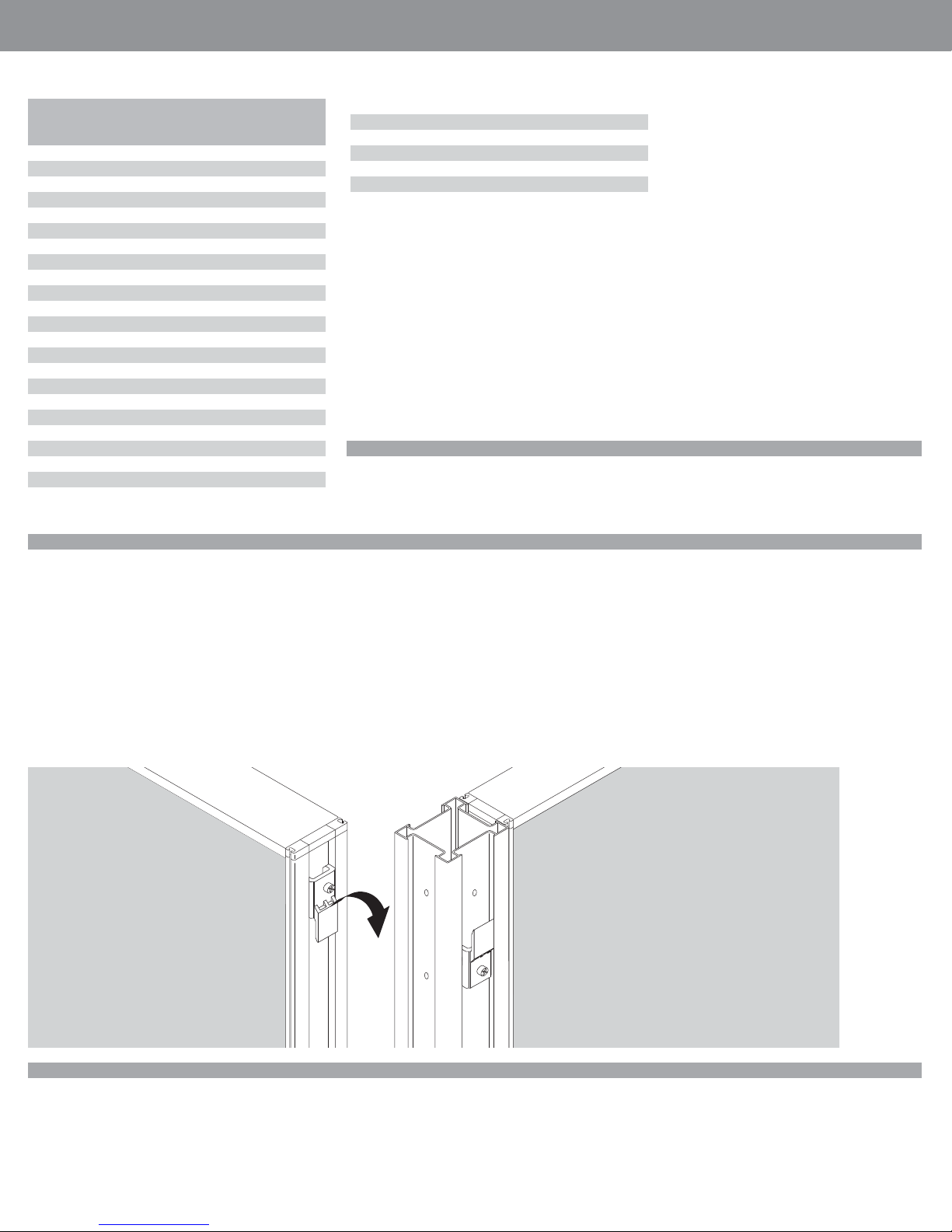
PANELS come from the factory with the “Quick Connect” clips pre-installed on both
sides of the panels. One side is pointing up and the other side is pointing down.
UNIVERSAL CORNER POSTS come from the factory with the “Quick Connect”
clips pre-installed on 3 sides. One side is pointing down, and 2 adjacent sides are
pointing up.
Slide connections together, and press fi rmly in place. Do not use hammer to try
to secure panels.
Leveling Tip:
• If panels don’t line up exactly, please lower the glide on the lower panel to level
the panels.
15
15
16
16
17
18
19
Corner Post Tips:
• Align the “Quick Connect” clips on the fi rst panel of a run so both sides point UP.
This will allow the Corner Post to be dropped onto one side, and the adjacent
panels to also be dropped on. Then the rest of the panels in the run can be easily
dropped onto each other.
• For 2 ways, remove one set of clips by loosening the set screw, and slide up and
out, through the channel. Snap in 2 Post Trim Strips to fi nish 2 open sides.
• For 3-ways, snap in Post Trim Strip to fi nish 4th side.
• For 4-ways, install the clips on the 4th side facing up, so the panel can be
dropped on.
Please contact your Global Contract Service Representative at 416-739-5000 for
any questions or concerns.
NOTE: Any alterations to listed components will void the manufacturer’s warranty.
The manufacturer will not be responsible for any damage or bodily harm caused
by alterations in accordance with national or local electrical codes and manufac-
Page • globalcontract.com1
turer’s specifi cations. In accordance with the manufacturer’s policy of continual
product improvement, the product presented in this document is subject to
change without notice or obligation.
Page 3
GLOBALContract
Quick Connect Clips
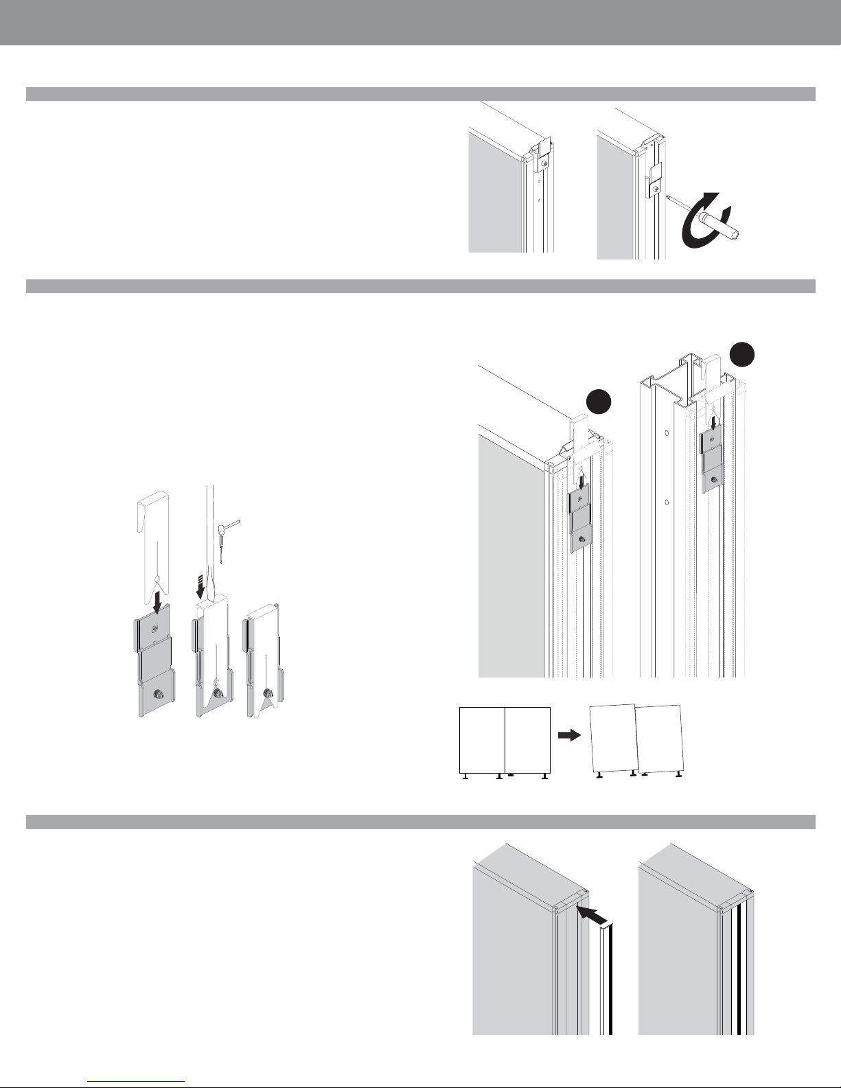
Add or remove “Quick Connect” clips with a Phillips screwdriver, by loosening the
screw enough to allow the clip to slide freely.
To remove clip, lift tab on top of panel and slide clips out of groove.
To change clip orientation, use the following hole confi gurations.
• Top hole to have clip point down.
• Bottom hole to have clip point up.
Lock Clips
Post: (a)
Put the lock clip in such a way that the short end of the clip is over the top connector
and the longer side is facing the panel (even if it’s on an angle). Using a mallet and a
fl at screwdriver, hammer the lock clip down until you feel it catch the lower screw.
Between Panels: (b)
Put the lock clip in such a way that the short end of the clip is over the top connector
and the longer side is facing the panel. Using a mallet and a fl at screwdriver, hammer
the lock clip down until you feel it catch the lower screw.
• Summer 2017
INSTALLATION GUIDELINES
a
b
Releasing the lock clip:
Pull the leveler (sdjustor) downat the panel that it’s connector is on top and push the
other panel down.
Panel Trims
Panel / Post Trims can snap or slide into place, to fi nish panel End of Runs, 2-way,
3-way and step down-variable height connections.
NOTE: End of Run Trims are approximately 5” longer than Post Trims.
•Page globalcontract.com 2
Page 4
GLOBALContract
INSTALLATION GUIDELINES
CAPAS Privacy Glass
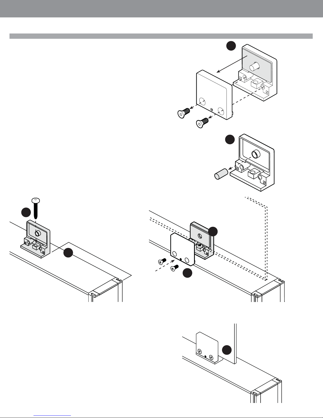
STEP 1: Open the clamps.
STEP 2: Remove the pin.
STEP 3: Measure 5” from the edge.
STEP 4: Drill directly into the top of the panel. (use the provided #10 1 1/2” pan head
square drive type A screw.)
STEP 5: Use the thicker rubber pad if two different size pads are provided in the box.
STEP 6: Leave the clamps loose, carefully slide the glass in and then tighten both
clamps evenly so the glass is snug and vertical. the middle set screw will control the
pitch.
• Summer 2017
1
2
4
5
3
5”
6
6
Page • globalcontract.com3
Page 5
GLOBALContract
Post Base Covers
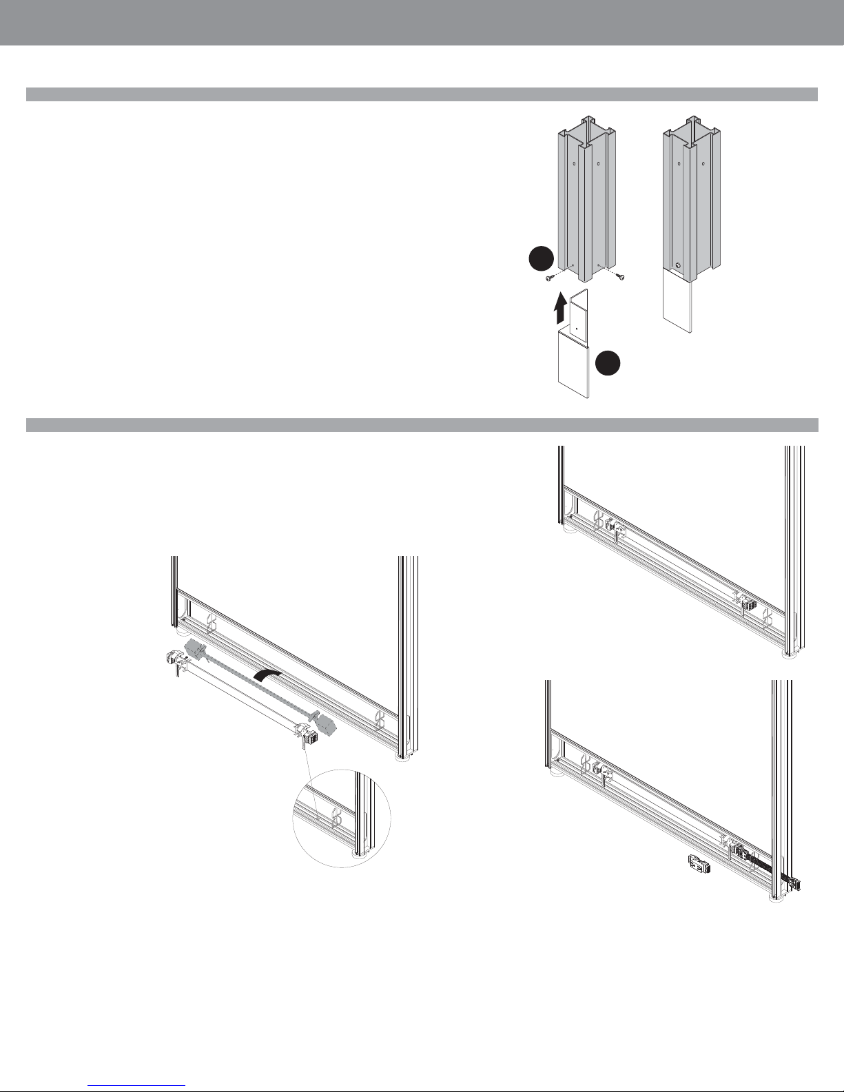
STEP 1: Slide Post Base Cover into bottom of Universal Corner Post.
STEP 2: Secure into place on 2 sides, with two small black screws.
• Summer 2017
INSTALLATION GUIDELINES
2
1
Electrical - Adding Power Distribution Housing
Align Power Distribution Housing so the bottoms tabs drop into the pre-cut slots in the
panel base. Be sure to align the spring clips on top, so they are facing you.
Rotate Power Distribution Harness into place until the spring snap securely into
place.
Included cable managers can be slid to the side, or removed.
•Page globalcontract.com 4
Page 6
GLOBALContract
INSTALLATION GUIDELINES
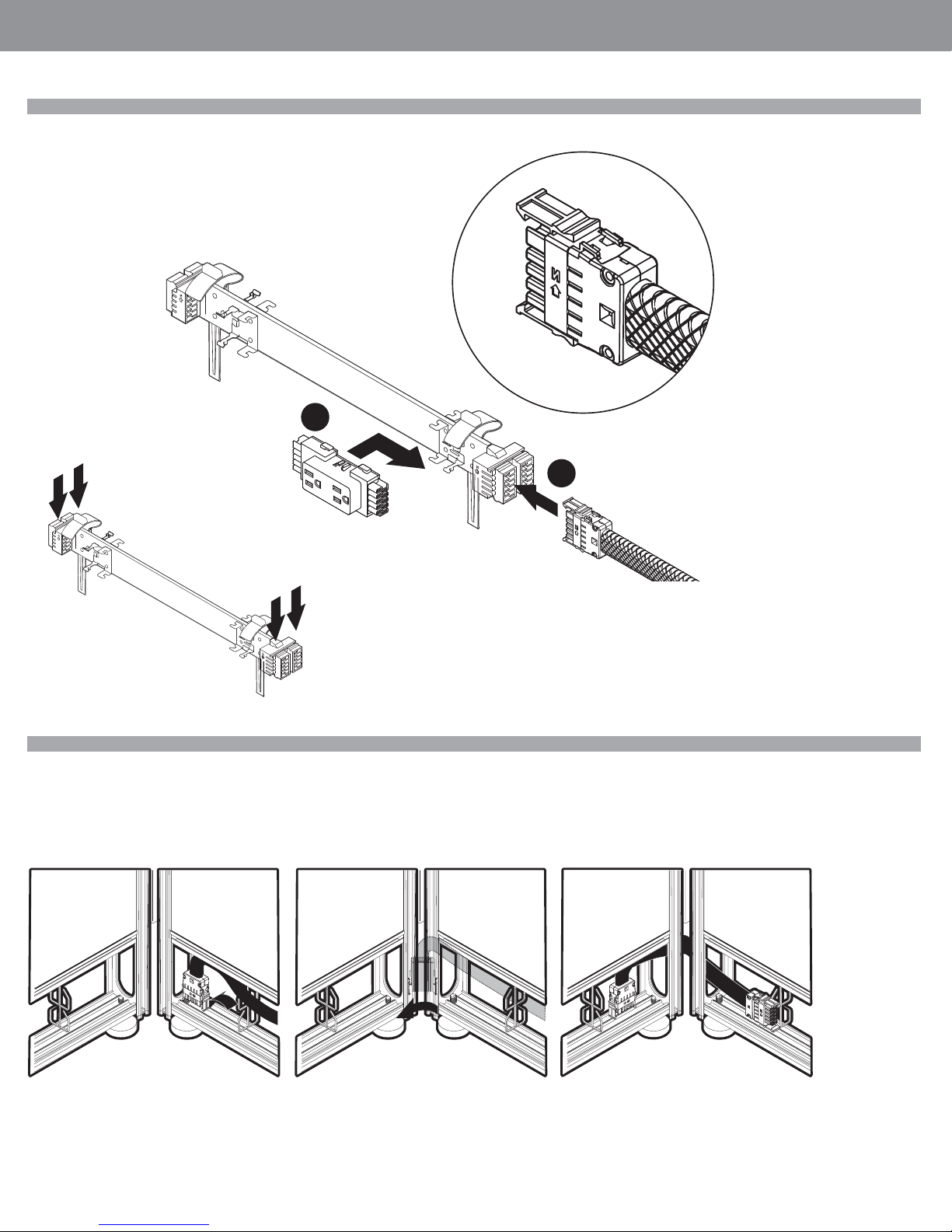
Electrical - Power Distribution Harness and Duplexes
STEP 1: Plug Jumper into Power Distribution Harness, until it clicks fi rmly into place.
The arrow above the embossed “N”, should be pointing up.
STEP 2: Slide Duplex into place, until it clicks fi rmly into place.
2
• Summer 2017
1
Power Distribution Harness has two
ports on each side to plug in additional
Jumpers or Ceiling Feeds.
Electrical - Installing Through Corners
Installation Tip: When routing jumpers around corners, in a 2-way, 3-way or
4-way connection.
Bend connection of 17” fl exible Mesh Jumper downward, at a 90 degree angle.
Slide connector through opening and pass through openings in both panels.
Straighten connector.
Page • globalcontract.com5
Page 7
GLOBALContract
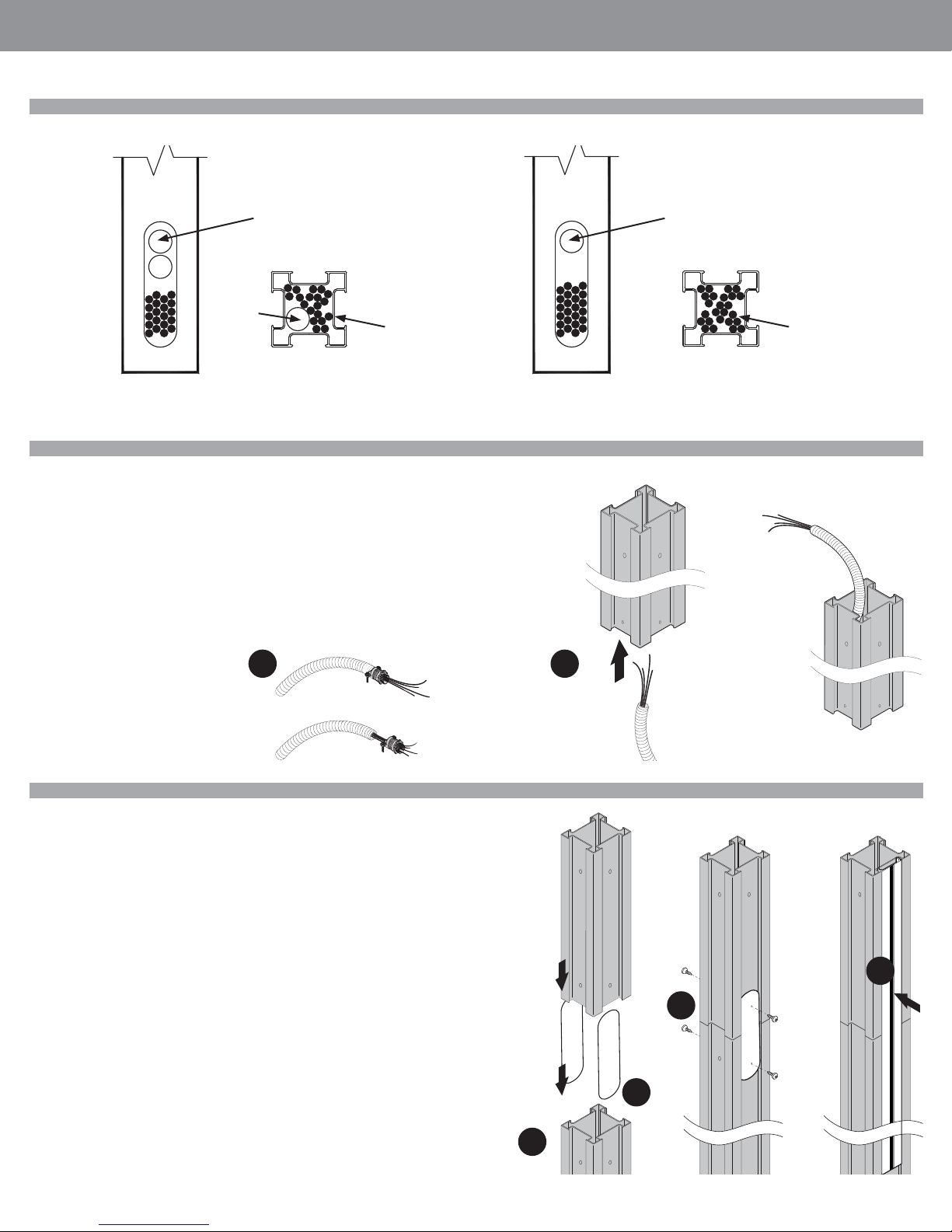
Electrical - 90 degree post cable capacity
Typical application, recommended maximum
• Summer 2017 rev:Winter 2018
• Summer 2017
INSTALLATION GUIDELINES
With Power
Panel Frame
Pass Through Cable
Power Feed
(0.73” dia)
20x CAT6 Cables
0.25” dia
Post
* THESE ARE GUIDELINES ONLY, ACTUAL NUMBERS MAY VARY BASED ON SITE
CONDITIONS AND CLIENT REQUIREMENTS *
Electrical - Ceiling Feed
STEP 1: Disconnect clamp at top of ceiling feed, and remove, tape the wires together.
STEP 2: Lay the Universal Corner Post on the fl oor. Slide top of ceiling feed
through Universal Corner Post, starting at the bottom of the post.
STEP 3: Lay Post Extension inline with the Universal Corner Post. Slide Ceiling
Feed through the Post Extension. Attach Post Extension connector plates as
indicated in Post Extension instructions, on this page, below.
STEP4: Reattach connector clamp to top of ceiling feed. Install completed Power
Pole onto panels, and into ceiling.
Without Power
Panel Frame
Pass Through Cable
25x CAT6 Cables
0.25” dia
Post
1
Post Extension
STEP 1: Drill a 6mm hole, screw bottom of attachment plates into universal
corner post. Use two plates, opposite to each other for each post extension.
STEP 2: Slide Post Extension Post between attachment plates.
STEP 3: Drill a 6mm hole. Screw top of attachment plates into post extension.
STEP 4: Snap Trims into grooves on all 4 sides of Post Extension. Trim dimension
matches post dimension.
2
4
3
2
1
•Page globalcontract.com 6
Page 8
GLOBALContract
INSTALLATION GUIDELINES
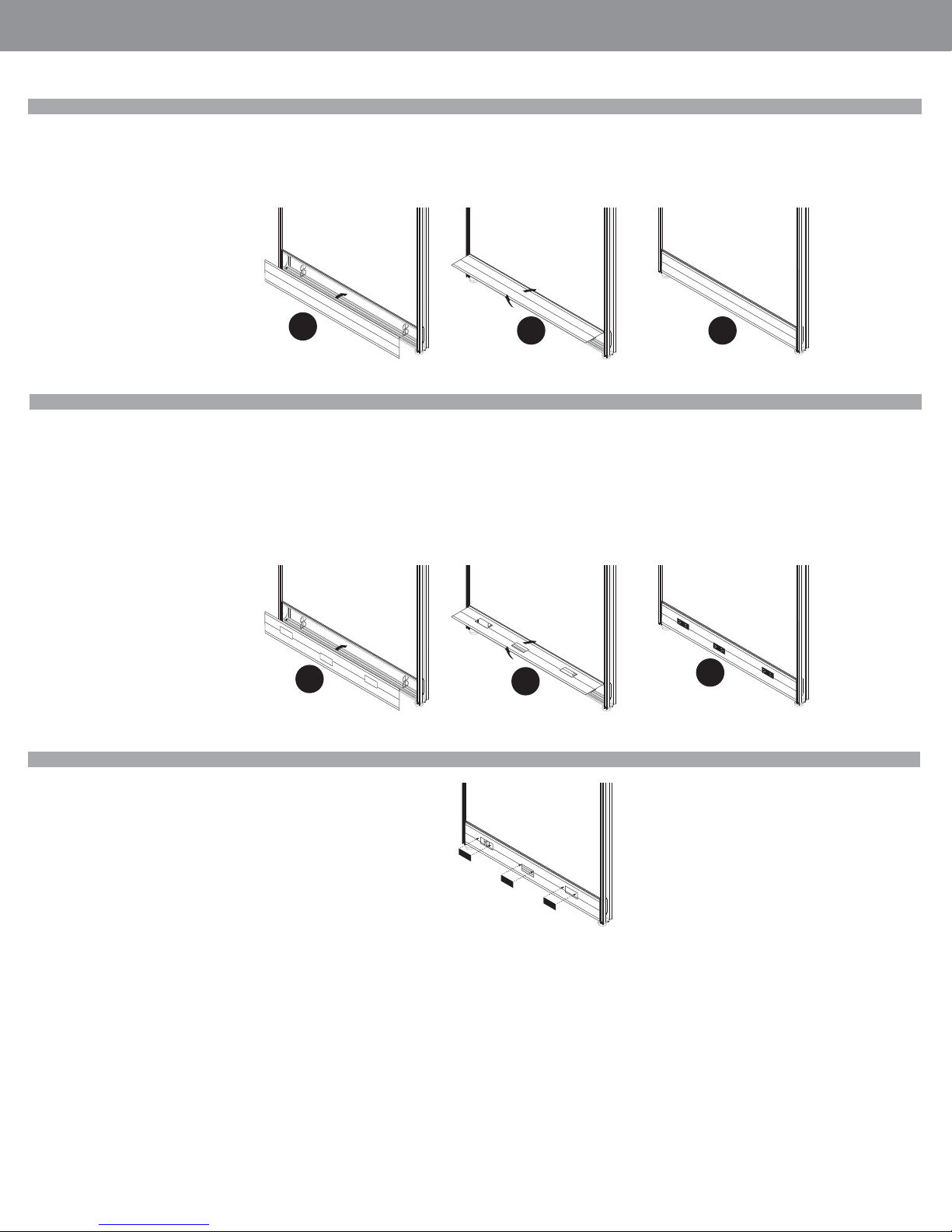
Raceway Covers without Knockouts
STEP 1: Orient Raceway Cover until it is almost VERTICAL and insert top of cover
into groove on panel.
STEP 2: Raceway Cover can be lifted up at 90 degrees, and pushed slightly into
panel, to lock in place.
STEP 3: Snap bottom corners of Raceway Covers, to secure into place.
• Summer 2017
1
Raceway Covers with Knockouts
STEP 1: Orient Raceway Cover until it is almost VERTICAL and insert top of cover
into groove on panel.
STEP 2: Raceway Cover can be lifted up at 90 degrees, and pushed slightly into
panel, to lock in place.
STEP 3: Snap bottom corners of Raceway Covers, to secure into place.
STEP 4: Raceway Covers lock securely in place on both ends, securing over black
tabs in panels.
1
Raceway Knockout Covers
Snap Raceway Knockout Covers into openings where duplexes are not being used.
2
2
3
3
Page • globalcontract.com7
Page 9
GLOBALContract
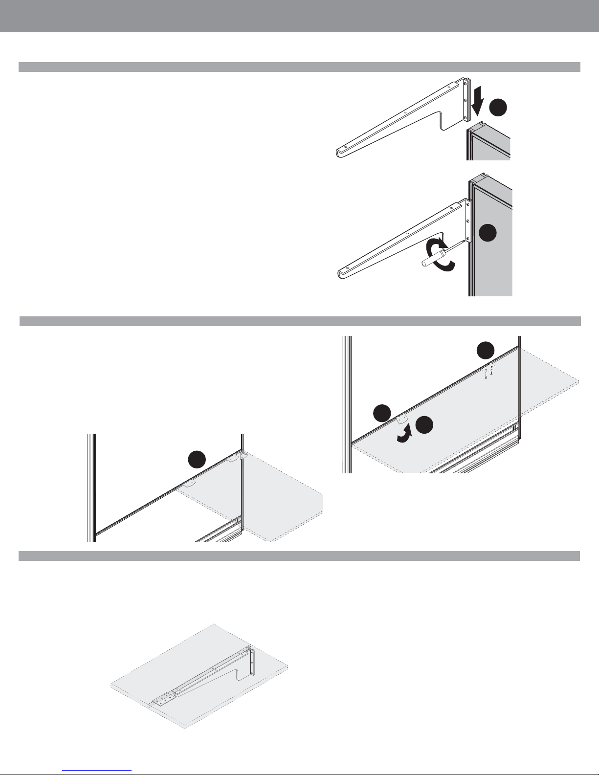
Cantilevers / Corner Brackets
Installation Tip:
• Summer 2017
INSTALLATION GUIDELINES
• Build from the BOTTOM....UP!
• Slide all Worksurface Supports and Brackets into place...FIRST. Tackboards/Writeboards /Load Bars, SECOND. Overhead Storage / Shelves, THIRD.
STEP 1: Slide worksurface supports, with connection plate and screws attached,
into groove on side of panel.
STEP 2: Make sure that the screws are fl ush, and do not protrude through the
connection plate.
STEP 3: Securely attach all screws using a #4 ALLEN BIT, or TORX T25 HEAD BIT.
Gauges are provided with every cantilever and corner bracket.
Mid Span Support Brackets (Can ONLY be used with Segmented Panels)
STEP 1: Insert bottom portion of Mid Span Support bracket into segmentation
channel, below worksurface height.
STEP 2: Lift bracket to secure it into segmentation channel.
1
3
3
STEP 3: Secure bracket to worksurface using short wood screws.
STEP 4: Mid Span Support Brackets can be used as additional support for longer
worksurfaces or to create an off-module connection, as shown.
4
Adjacent Worksurface Mounting
Two Cantilevers, leveled side-by-side with Flat Plate to align front edges of
worksurfaces.
One Corner Bracket, plus (2) Mid-Span Support Brackets (using Segmented
Panels ONLY) to create an off-module worksurface connection.
1
2
•Page globalcontract.com 8
Page 10
GLOBALContract
INSTALLATION GUIDELINES
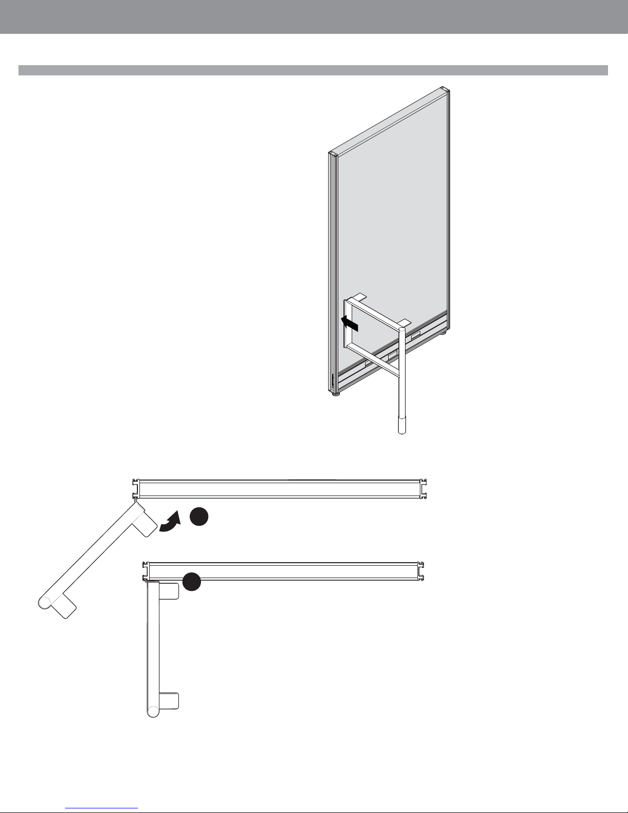
CHMEG Metal End Gable
STEP 1: Engage the leg into the panel’s rail by rotating it into place.
STEP 2: Install the worksurface while making sure the leg is perpendicular to the panel.
• Summer 2017
1
2
Page • globalcontract.com9
Page 11
GLOBALContract
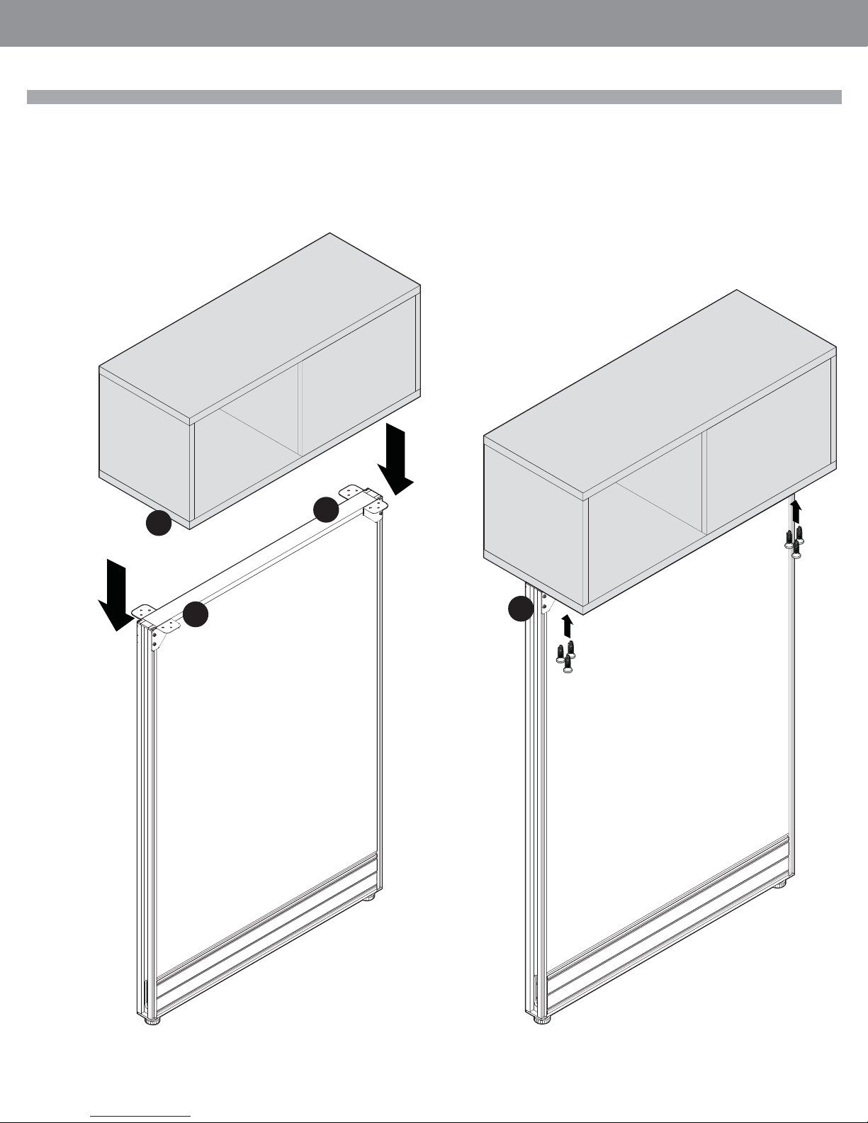
Centre Mounted Overhead
1. Install the corner brackets so they align with the very top of the panel.
2. Measure and centre the overhead on top of the panel.
3. While someone holds it in place, fasten the overhead to the brackets with the
provided screws.
• Summer 2017
INSTALLATION GUIDELINES
2
1
1
3
•Page globalcontract.com 10
Page 12
GLOBALContract
INSTALLATION GUIDELINES
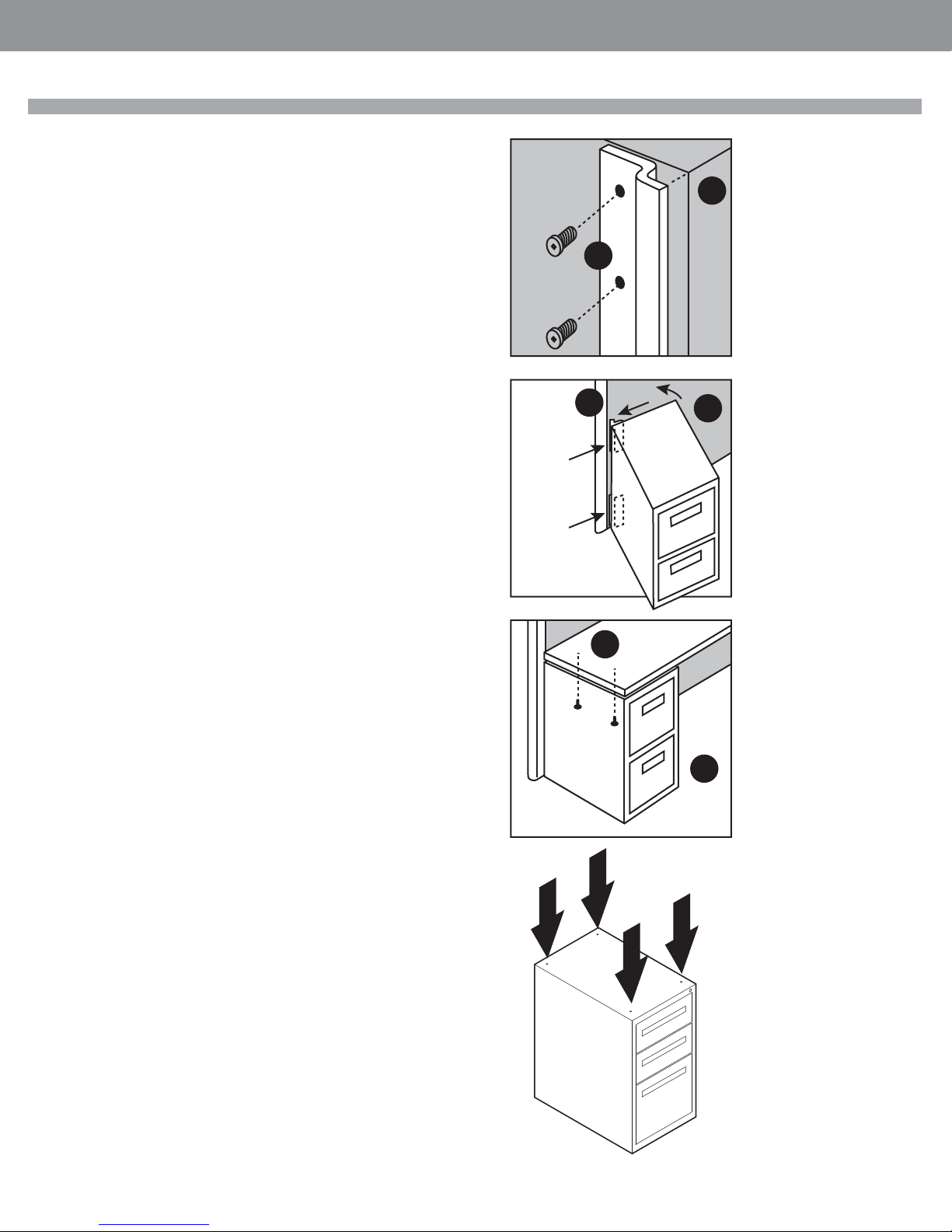
Pedestal Bracket / Corner Plate
Ensure that all panels are leveled and securely connected before proceeding with
installation of worksurfaces supports.
STEP 1: Align the fi rst bracket’s edge with pedestal’s top corner and rear vertical edge
as illustrated.
STEP 2: Secure the top bracket with supplied, self-drilling, counter-sunk head screws.
• Summer 2017
1
STEP 3: Align the second bracket’s bottom edge with pedestal’s bottom corner and
rear vertical edge and secure it with supplied, self-drilling, countersunk head screws.
(Not shown).
STEP 4: Angle the pedestal on the fl oor and insert bracket ends into panel’s vertical
side groove.
STEP 5: Rotate the pedestal while making sure that both brackets remain securely
engaged inside the panel’s vertical side groove. Install worksurface support on the
opposite side of the worksurface as specifi ed. Rest worksurface on both supports.
STEP 6: Adjust pedestal’s levelers to level the worksurface and ensure that the pedestal’s side is perpendicular to the panel.
NOTE: Read before you proceed with the next step! If you use a full depth pedestals
( 24” deep pedestal under 24” deep worksurface) to secure worksurfaces to a panel
with optional Panel cable manager, do not bolt the pedestal to the worksurface yet.
You may have to angle and slide the pedestal partially out in order to gain an access
to the panel’s cable manager. In this case, the following step (#7) should be done at
the end of the installation, after all cables had been tucked away in the Panel cable
manager.
STEP 7: Remove drawers, pre-drill the pedestal top and drive two wood screws
through the pedestal top, into the worksurface. Replace the drawers and secure the
opposite side of the worksurface to its support.
TOP
BRACKET
BOTTOM
BRACKET
2
4
5
7
Compile Pedestals come shipped with cardboard protection on top, bottom and all four
corners, and then shrink wrapped.
Compile Pedestals may be stacked up to 3 high, in the shipping trailer, during
delivery.
All Worksurface Supporting Pedestals ship with holes punched in the tops, on all
four corners, to allow simple attachment to worksurfaces., using wood screws
less than 1” long.
Compile Pedestals ship with leveling glides on all four corners. Please use a drill,
with standard drill bit extension, to level pedestal to proper height, prior to attaching screws to worksurface.
Page • globalcontract.com11
6
Page 13
GLOBALContract
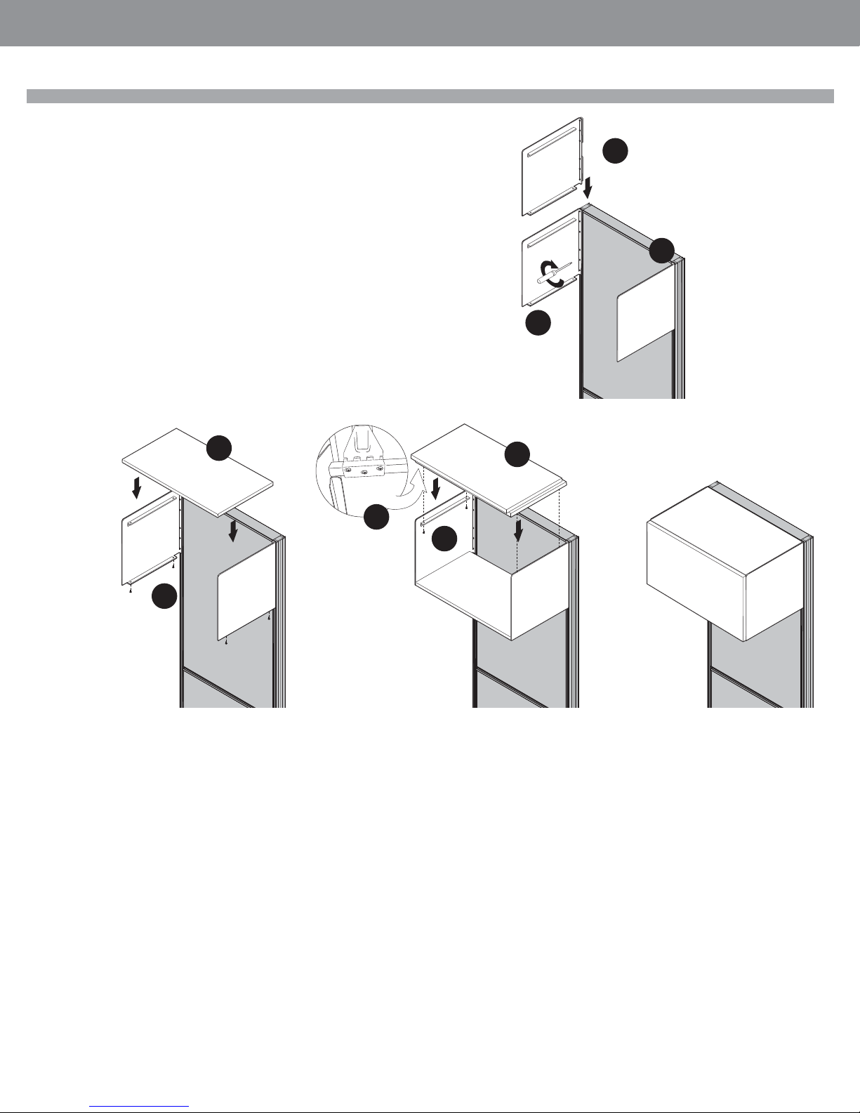
Overhead Storage Bins
STEP 1: Slide overhead side supports, with connection plate and screws attached,
into groove on side of panel.
• Summer 2017
INSTALLATION GUIDELINES
STEP 2: Align top of overhead side support with top of panel.
STEP 3: Securely attach all screws using a #4 ALLEN BIT, or TORX T25 HEAD BIT.
STEP 4: Place bottom shelf on top of bottom brackets.
STEP 5: Securely attach all screws using a #2 Phillips bit.
STEP 6: Place top shelf, with door attached, on top of brackets.
STEP 7: Securely attach all screws using a #2 Phillips bit.
STEP 8: Oblong holes in door slider hardware ,allow door to be centered on cabinet.
4
8
7
1
2
3
6
5
•Page globalcontract.com 12
Page 14
GLOBALContract
INSTALLATION GUIDELINES
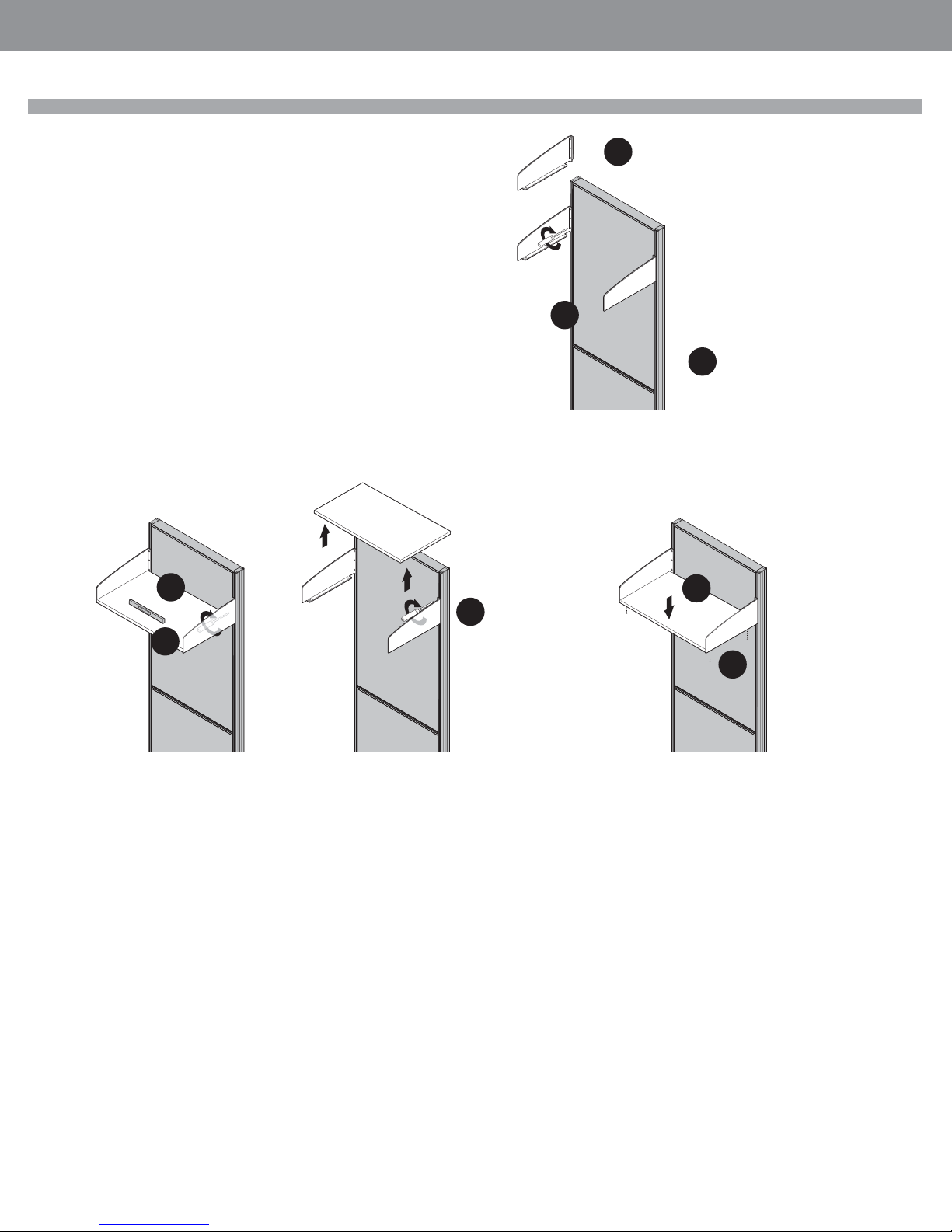
Low Profi le Shelves
STEP 1: Slide Low Profi le side supports, with connection plate and screws attached, into groove on side of panel.
STEP 2: Align bottom of Low Profi le side support with bottom of Overhead Storage Cabinet, if applicable, use the supplied shelf gauge
STEP 3: Securely attach all screws using a #4 ALLEN BIT, or BALL TORX T25 BIT,
on one side only.
STEP 4: Securely attach ONE screw using a #4 ALLEN BIT, or BALL TORX T25
BIT, on second side only.
• Summer 2017
1
STEP 5: Place bottom shelf on top of bottom brackets.
STEP 6: Using a level, hold second shelf side, loosen screw. Align shelf side until level.
STEP 7: Remove bottom shelf and securely attach all cap nuts.
STEP 8: Replace bottom shelf on top of bottom brackets.
STEP 9: Securely attach all screws using a #2 Phillips bit.
5
6
3
2
8
7
9
Page • globalcontract.com13
Page 15
GLOBALContract
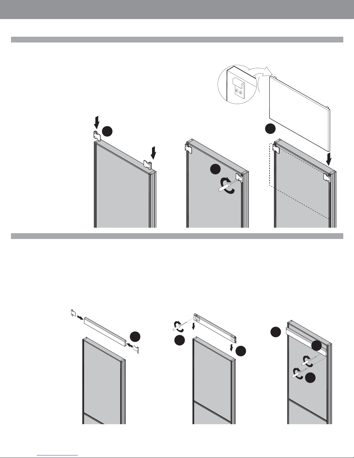
Tackboards
STEP 1: Slide universal brackets, with connection plate and screws attached, into
grooves on each side of panel.
STEP 2: Securely attach all screws using a #4 ALLEN BIT, or TORX T25 HEAD BIT.
STEP 3: Hang tackboard hooks, into notches on universal bracket.
• Summer 2017
INSTALLATION GUIDELINES
1
Load Bar
STEP 1: Attach universal brackets, with connection plate and screws attached,
into groove on back of Load Bar.
STEP 2: Attach end caps to both sides, to secure the Load Bar to the universal
brackets.
STEP 3: Slide Load Bar with bracket assembly into grooves on sides of panels.
STEP 4: Position Load Bar into desired position, using a level.
3
2
STEP 5: Securely attach all screws using a #4 ALLEN BIT, or TORX T25 HEAD BIT.
2
1
5
3
6
•Page globalcontract.com 14
4
Page 16
GLOBALContract
INSTALLATION GUIDELINES
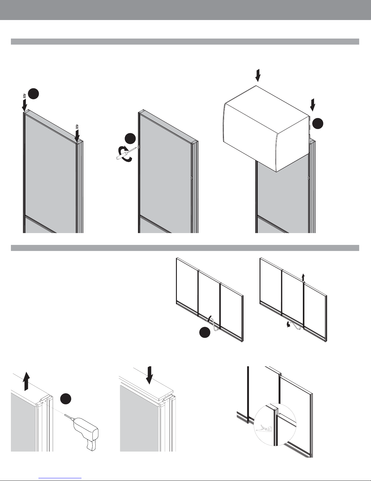
ADA Overhead
STEP 1: Slide down the supplied 2 - two hole sliders into the side groves of the
panel to their position using a gauge. Typical installation is 15” from the top of
the panel.
STEP 2: Slide the ADA from top down until you meet with the 2 hole sliders
already installed.
1
1
• Summer 2017
2
Mid Run Panel Removal & Top Horizontal Replacement
STEP 1: Insert the crowbar under the bottom of the vertical and lift until the connectors at the top disengage.
STEP 2: Repeat the above step and release the panel from the row.
STEP 3: Screw out the two screws (each side) and release the top horizontal.
Replace with the new top horizontal.
STEP 4: Drop down one side of the panel then drop down the following side into
the connectors. (Use clamp vise grips to bring the panels close to each other
while the drop down panel is raised above the connectors.)
3
1
Page • globalcontract.com15
Page 17
GLOBALContract
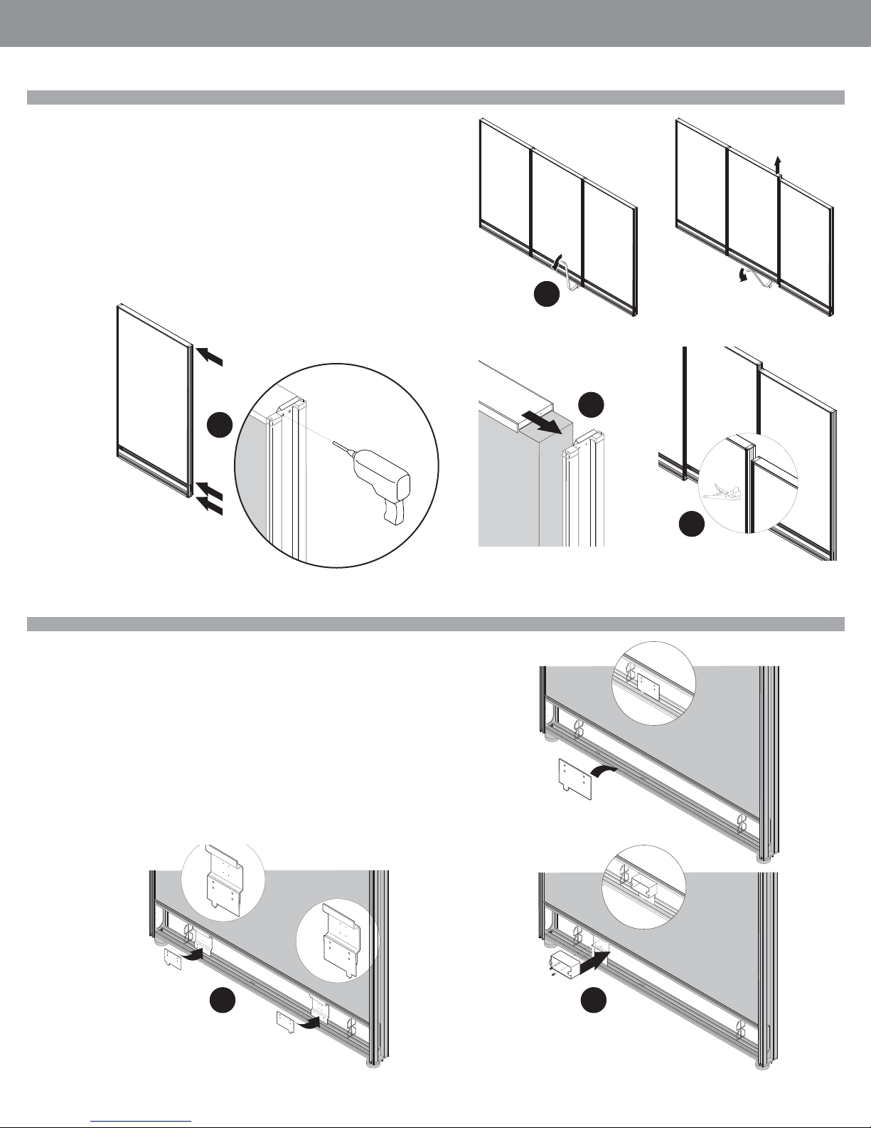
Core Replacement
STEP 1: Insert the crowbar under the bottom of the vertical and lift until the connectors at the top disengage. Repeat for the other side and release the panel from
the row.
STEP 2: Unscrew both side verticals and the bottom 2 screws
STEP 3:Slide out the core and replace with new fabric one.
STEP 4: Screw back all the vertical side and 2 bottom screws
STEP 5: Drop down one side of the panel then drop down the following side into
the connectors. (Use clamp vise grips to bring the panels close to each other
while the drop down panel is raised above the connectors.)
• Summer 2017
INSTALLATION GUIDELINES
1
3
2
Chicago J-Box
STEP 1: Insert the bottom bracket into the power distribution slot.
STEP 2: Insert the top bracket into the inner groove and place it in front of the
bottom bracket.
STEP 3: Take the Junction Box and attach it to the two brackets with supplied hex
screws.
5
2
3
•Page globalcontract.com 16
Page 18

GLOBALContract
INSTALLATION GUIDELINES
Module Replacement
Applies to: fabric or laminate replacement. Conversion from glass to fabric, or
fabric to glass.
STEP 1: Remove the square #1 screws along the vertical part of the panel frame.
*DO NOT remove the Philllips screws found at the bottom!
STEP 2: Carefully remove the piece without causing ant damage.
STEP 3: If replacing a fabric module, remove the screws on the other side of the
panel, then slide the fabric module out.
*Steps 4 and 5 are for glass modules. If replacing fabric, skip to step 6.
STEP 4: Slide the glass out.
STEP 5: Carefully pry the glass frame off using a pick or a screwdriver.
*avoid damaging the panel components!
STEP 6: Slide the new fabric module in.
STEP 7: Carefully reattach the vertical part of the panel frame and gently close any
visible gaps between the pieces.
• Summer 2017
STEP 8: Reinstall all the screws and check for any gaps around the panel frame.
Reinstall all the screws and check for any gaps around the panel frame.
STEP 9: If the new screws were shipped along with the new fabric module, install
them as well.
Page • globalcontract.com17
Page 19
GLOBALContract
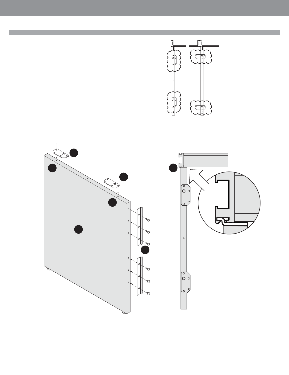
End Panel
STEP 1: Align the holes of the worksurface brackets (1) with the pilot holes (2)
on the top of the end panel (3). Drive the supplied screws into the end panel but
do not over tighten.
STEP 2: Attached the panel mounting brackets (4) to the end panel, while aligning the bracket holes with the pilot holes of the end panel.
STEP 3: Attach the end panel to the Compile panel’s vertical rail (5). Put it on an
angle then rotate it into its place.
STEP 4: Adjust the levelers as needed, making sure the end panel will keep the
worksurface level.
STEP 5: Proceed with the installation of the worksurfaces.
• Summer 2017
INSTALLATION GUIDELINES
Installation Tip: Identify correct setting
of worksurface mounting brackets (left
and right, single or supporting adjacent
worksurface) and install the panel
mounting bracket accordingly.
1
2
5
1
2
3
4
•Page globalcontract.com 18
Page 20
GLOBALContract
INSTALLATION GUIDELINES
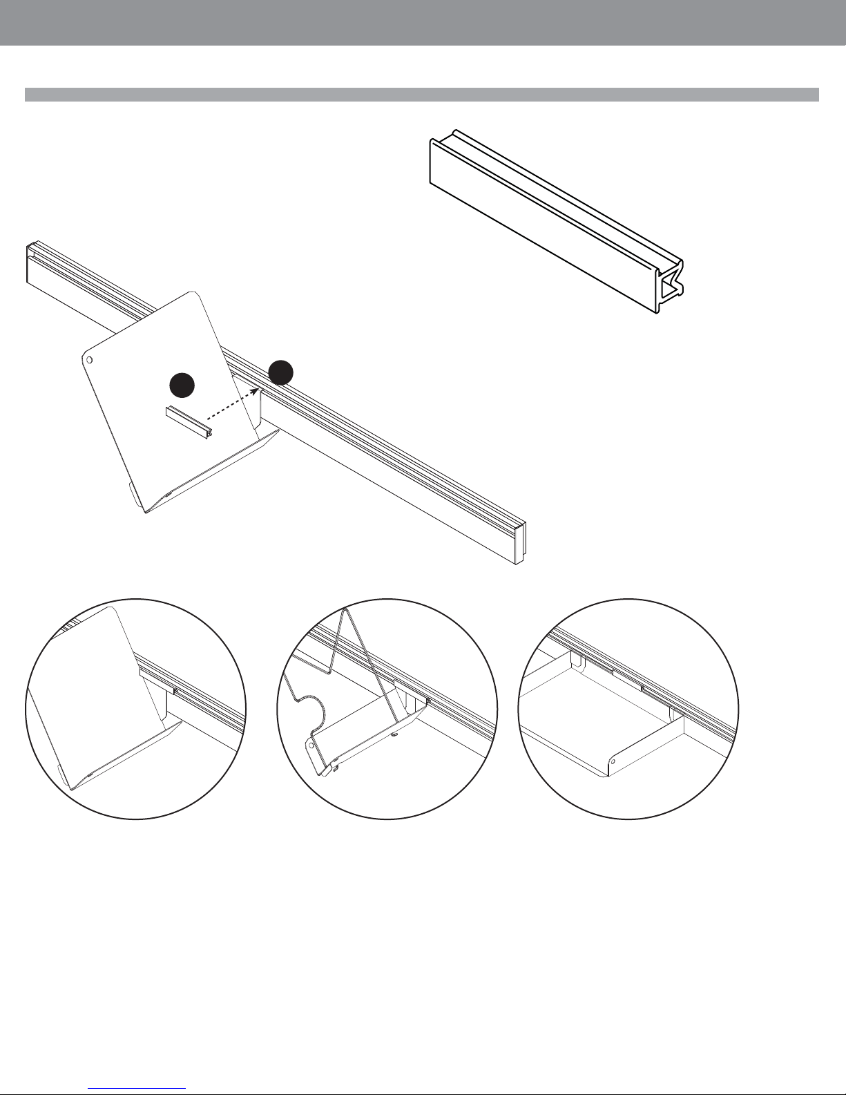
Accessory Retainer
STEP 1: Mount the accessory on the load bar.
STEP 2: Push the accessory retainer (1) into the gap above the accessory (2) to
lock it into place.
• Summer 2017
3” black rubber retainer for use with
paper management accessories.
This locks and prevents accessories
from falling off the load bar.
2
1
Page • globalcontract.com19
Page 21

GLOBALContract
• Summer 2017
•Page globalcontract.com 20
Page 22

GLOBALContract
GLOBALContract
GLOBALContract
THE GLOBAL GROUP SHOWROOM
1350 Flint Road, Toronto, Ontario, M3J 2J7
Sales & Marketing • TEL: 1-877-446-2251 • FAX: 416-667-0338
Customer Service • TEL: 416-739-5000 • FAX: 800-361-3182
VANCOUVER SHOWROOM
3823 Still Creek Avenue Burnaby, BC, V5C 4E2 • TEL: 604-432-1701
EDMONTON SHOWROOM
17716 107 Avenue NW Edmonton, AB, T5S 1G8 • TEL: 780-444-8922
CALGARY SHOWROOM
302 - 237 8 Avenue SE Calgary, AB, T2G 5C3 • TEL: 403-250-7770
WINNIPEG SHOWROOM
1-1080 Waverley Street N Winnipeg, MB, R3T 5S4 • TEL: 204-925-3350
OTTAWA SHOWROOM
251 Laurier Avenue West, 4th Floor, Ottawa, ON, K1P 5T6
• July 2012
• June 2016
• Summer 2017
MONTREAL SHOWROOM
980 St-Antoine rué Ouest Montreal, bureau 200, QC, H3C 1A8 • TEL: 514-866-4331
HALIFAX SHOWROOM
1310 Hollis Street, Suite 150, Halifax, NS, B3J 3P3 • TEL: 902-422-7434
QUEBEC SHOWROOM
Complex Lebourgneuf 2, 815, boul. Lebourgneuf, Suite 502 Quebec, QC, G2JOC1 • TEL: 418-653-6111
Visit us on the Internet at globalcontract.com
Page • globalcontract.comH.16
Page • globalcontract.com21
Page • globalcontract.comH.14
 Loading...