

Page 1
Global Connect
User Guide
1.0 INTRODUCTION
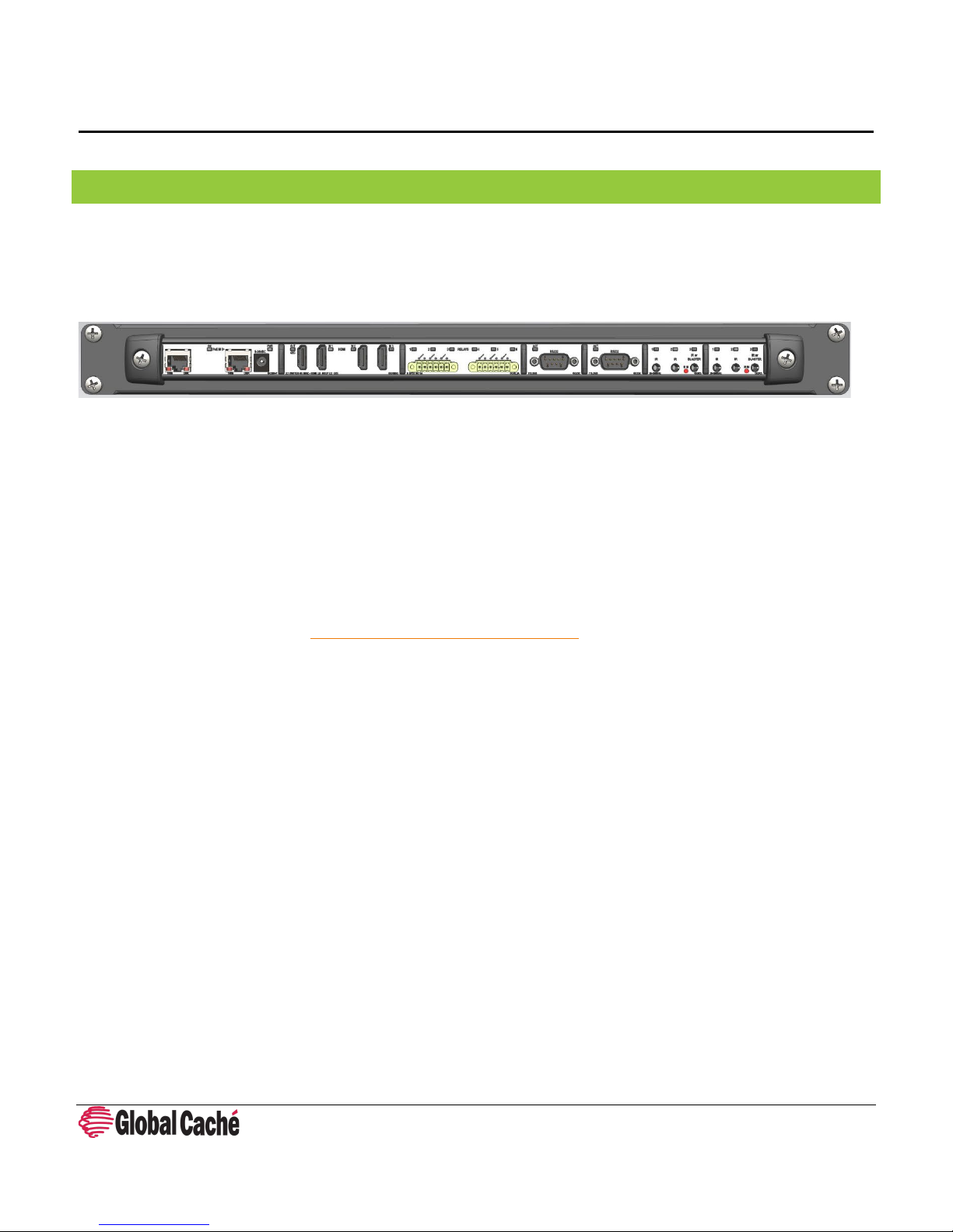
Global Caché's modular Global Connect is the newest high-performance family of connectivity products from the company
that has revolutionized the way you connect, command, and control. Built with performance, flexibility, and empowering in
mind, Global Connect delivers a simple cost-effective way to extend the reach of any control system, from legacy hardwarebased systems to leading-edge cloud-based control software; from current projects to future installations.
Known for award-winning products connecting infrared (IR), serial (RS232 and 485), relay, and sensor input, to a WiFi or IP
network, Global Caché introduces Global Connect, adding the ability to build the scalable I/O you need, with customizable
configuration, and added modules including local computing capability (Raspberry Pi slot), and HDMI switching. Global
Connect features individual IP addresses for each module with individual web pages for easy configuration and advanced
addressability.
This document intends to provide additional information, insight, and instruction on installing, configuring, and using Global
Connect.
For initial setup instructions, or TCP and HTTP APIs please refer to the Global Connect Quick Start, or Global Connect APIs
respectively on our downloads page: http://www.globalcache.com/downloads
Global Connect User Guide 160 East California Street, PO Box 1659
Effective: January 10, 2019 Jacksonville, Oregon 97530
PN: 103118-01 ver. 1 Phone: 541-899-4800
Page 1 Fax: 541-899-4808
www.globalcache.com
Information subje ct to change withou t notice.
Page 2

Global Connect
User Guide
2.0 TABLE OF CONTENTS
1.0 Introduction ............................................................................................................................................................................. 1
2.0 Table of Contents ..................................................................................................................................................................... 2
3.0 Product Architecture ................................................................................................................................................................ 3
4.0 Discovering Modules on the Network ...................................................................................................................................... 3
4.1 Configuration Web Pages ..................................................................................................................................................... 3
5.0 Network Modules ..................................................................................................................................................................... 4
5.1 GCIP – Single Ethernet Network Module ............................................................................................................................. 4
5.2 GCSW/GCSW-P – Dual Ethernet Network Switch Module ................................................................................................... 5
5.3 Network Settings .................................................................................................................................................................. 5
5.3.1 DHCP and DHCP reservations ........................................................................................................................................ 6
5.3.2 Static IP addresses (Advanced) ...................................................................................................................................... 7
6.0 GCHMX3 – HDMI 3x1 switching Module .................................................................................................................................. 9
6.1 Consumer Electronic Control (CEC) ...................................................................................................................................... 9
6.2 HDMI Switching .................................................................................................................................................................... 9
7.0 GCIR3 - Infrared (IR) Control Module ..................................................................................................................................... 10
7.1 IR Transmitters ................................................................................................................................................................... 10
7.2 Obtaining Infrared (IR) codes ............................................................................................................................................. 12
7.3 Troubleshooting IR ............................................................................................................................................................. 12
8.0 GCSL232 – RS232 Serial Control Module................................................................................................................................ 14
8.1 Serial Configuration ............................................................................................................................................................ 14
8.2 DB9 Pinout.......................................................................................................................................................................... 15
8.3 Straight-Through and Null-Modem cables ......................................................................................................................... 16
9.0 GCRL3A – Relay Control Module (6 Relays) ........................................................................................................................... 16
9.1 Troubleshooting Relays ...................................................................................................................................................... 18
10.0 GCRPI – Raspberry Pi Module .............................................................................................................................................. 19
10.1 The Rasbperry Pi in Automation ...................................................................................................................................... 19
11.0 Factory Default ..................................................................................................................................................................... 20
Global Connect User Guide 160 East California Street, PO Box 1659
Effective: January 10, 2019 Jacksonville, Oregon 97530
PN: 103118-01 ver. 1 Phone: 541-899-4800
Page 2 Fax: 541-899-4808
www.globalcache.com
Information subje ct to change withou t notice.
Page 3

Global Connect
User Guide
3.0 PRODUCT ARCHITECTURE
Global Connect is a modular product. Each module has its own IP address, and configuration web pages. Modules can be
different sizes and occupy either 1, 2, or 3 slots in the unit chassis. The following chassis sizes are available:
• 19” freestanding enclosure with 10 available module slots
• 19” rack mount enclosure with 10 available module slots
• 15" freestanding enclosure with 10 available module slots
• 10.5" freestanding enclosure with 7 available module slots
• 7.5" freestanding enclosure with 5 available module slots
• 6" freestanding enclosure with 4 available module slots
• 4.5" freestanding enclosure with 3 available module slots
The modular design of Global Connect allows for simplified compatibility with previous Global Caché product drivers. Drivers
for previous products should generally be expected to work on Global Connect devices assuming the Global Connect
functionality existed on the product line the original driver was written for.
Note: Previous Global Caché devices did not include an HDMI switch.
The modularity of the Global Connect also allows for numerous factory assembled product combinations. For orderable
configurations please see our web site at http://www.globalcache.com.
4.0 DISCOVERING MODULES ON THE NETWORK
When a unit is initially connected to the network, or after it has been reset to factory defaults, its modules will obtain an IP
address. To determine what IP address has been obtained, download and run iHelp from our website at
http://www.globalcache.com/downloads. iHelp will discover any Global Caché units on the network and display their IP
address, and MAC address.
To learn more about the different ways Global Connect modules will obtain IP addresses visit section 5.3 Network Settings.
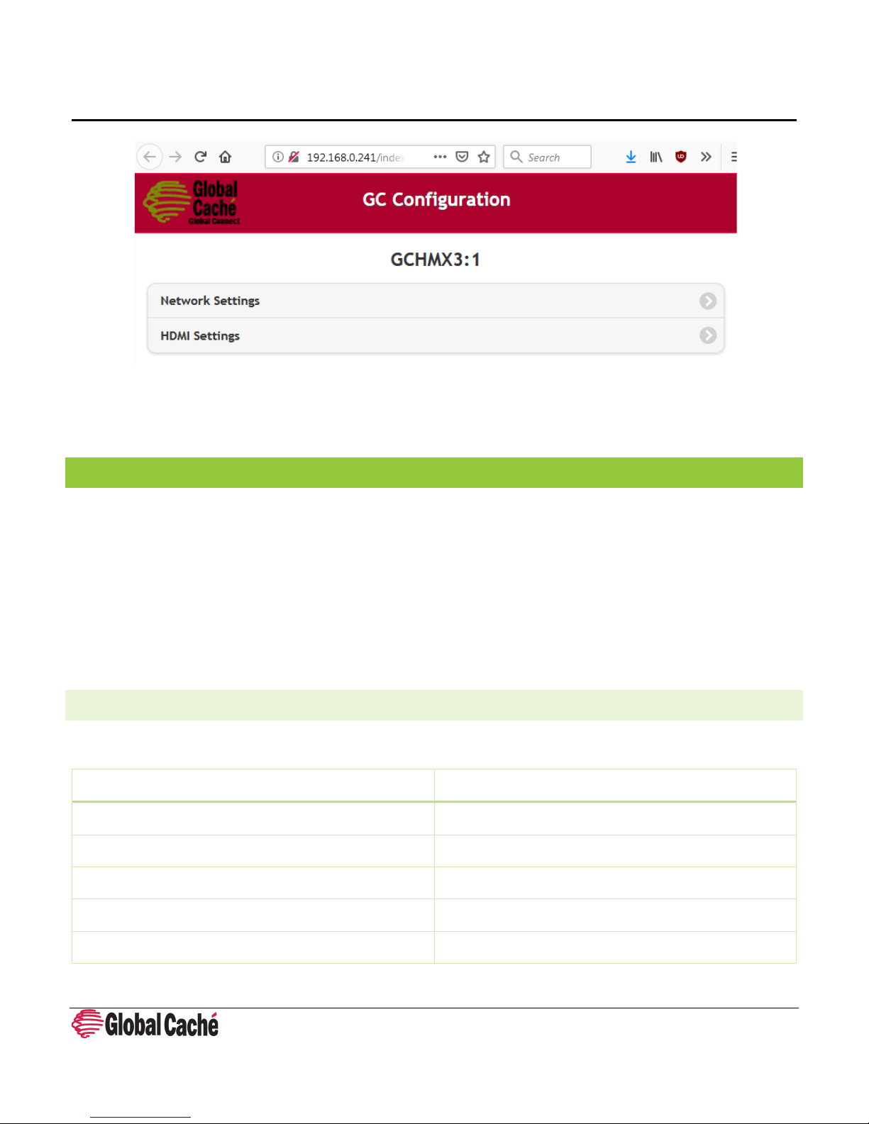
4.1 CONFIGURATION WEB PAGES
Once the IP address of a module has been obtained the configuration pages can be loaded by typing the IP address of the
module into a browser.
Global Connect User Guide 160 East California Street, PO Box 1659
Effective: January 10, 2019 Jacksonville, Oregon 97530
PN: 103118-01 ver. 1 Phone: 541-899-4800
Page 3 Fax: 541-899-4808
www.globalcache.com
Information subje ct to change withou t notice.
Page 4
Global Connect
GCIP Module Feature
Description
Network Connector
RJ45
Network Speed
100Mbps, Full Duplex
Power Connector
Barrel Jack: 5.5mm x 2.1mm (Center Positive)
Power Input
Range: 5V-24V
Chassis Slots Occupied
1
User Guide
From the configuration pages, network settings can be changed and the control interface can be configured. For more
information on network configuration see 5.3 Network Settings. For more information on control interface configuration see
the relevant section for the control module being configured.
5.0 NETWORK MODULES
Each Global Connect includes a network module. The network module provides the network connection for the unit. The
network module also provides the power input for the entire unit. Network modules can be powered with any power supply
between 5v and 24V DC. All Global Connect units ship with an appropriately rated power supply. The GCSW-P module
includes PoE capabilities. The GCSW-P module can be powered from any 802.3af compatible Power Sourcing Equipment
(PSE).
The power wattage requirement for a unit depends on the number and type of modules contained within the unit, however a
10W supply is suitable for all units that do not power a Raspberry Pi. For units that do power the Raspberry Pi a 5V 20W
power supply must be used.
5.1 GCIP – SINGLE ETHERNET NETWORK MODULE
The GCIP provides a hardwired networking solution to the Global Connect.
Global Connect User Guide 160 East California Street, PO Box 1659
Effective: January 10, 2019 Jacksonville, Oregon 97530
PN: 103118-01 ver. 1 Phone: 541-899-4800
Page 4 Fax: 541-899-4808
www.globalcache.com
Information subje ct to change withou t notice.
Page 5

Global Connect
GCSW/GCSW-P Module Feature
Description
Network Connector
2 x RJ45
Network Speed
100Mbps, Full Duplex
Power Connector
Barrel Jack: 5.5mm x 2.1mm (Center Positive)
Power Input
Range: 5V-24V
Power over Ethernet (PoE) capability (GCSW-P only)
802.3af Powered Device (PD)
Chassis Slots Occupied
2
User Guide
5.2 GCSW/GCSW-P – DUAL ETHERNET NETWORK SWITCH MODULE
The GCSW provides a hardwired networking solution for Global Connect devices with built in network switch capabilities.
The additional ethernet port and switch capabilities allow for daisy-chaining of Global Connect units, or to connect the
Raspberry Pi (in units that contain the Raspberry Pi module) to the network.
5.3 NETWORK SETTINGS
Network settings for Global Connect units are set individually on each Global Connect module. Modules support DHCP as well
as static IP address assignment.
When a unit initially connects to the network, or after a factory default, it will be assigned an IP address by the DHCP server.
To determine what IP address has been assigned, follow the instructions in section 4.0 Discovering Modules on the Network.
Global Connect modules installed on networks without a DHCP server will take a predetermined static IP address. The IP
address taken will be based on the module’s unit address. The unit address is the position that the module occupies in the
Global Connect chassis. The module that occupies the first position next to the network module will have unit address 1 and
will take IP address 192.168.1.71. Subsequent modules will take IP addresses 192.168.1.72, 192.168.1.73, and so forth.
Global Connect User Guide 160 East California Street, PO Box 1659
Effective: January 10, 2019 Jacksonville, Oregon 97530
PN: 103118-01 ver. 1 Phone: 541-899-4800
Page 5 Fax: 541-899-4808
www.globalcache.com
Information subje ct to change withou t notice.
Page 6
Global Connect
User Guide
The network settings for a module can be set through the unit’s configuration pages. Please refer to the Global Connect Quick
Start for instructions on accessing the configuration pages.
The Network Settings page is further described in sections 5.3.1 and 5.3.2 which deal with DHCP and Static IP address
assignments.
Many control apps and systems expect the IP address of Global Connect modules to remain the same. If the IP address of a
module changes (which can happen when using DHCP) the control software may not be able to communicate with the
module. To prevent this, we recommend creating a DHCP reservation (preferred) or assigning a static IP address to Global
Connect Modules.
5.3.1 DHCP AND DHCP RESERVATIONS
DHCP is the most common form of network IP assignment on residential and commercial networks. The purpose of a DHCP
server is to dynamically assign unique IP addresses to all connected network clients. DHCP is enabled by default on Global
Connect modules.
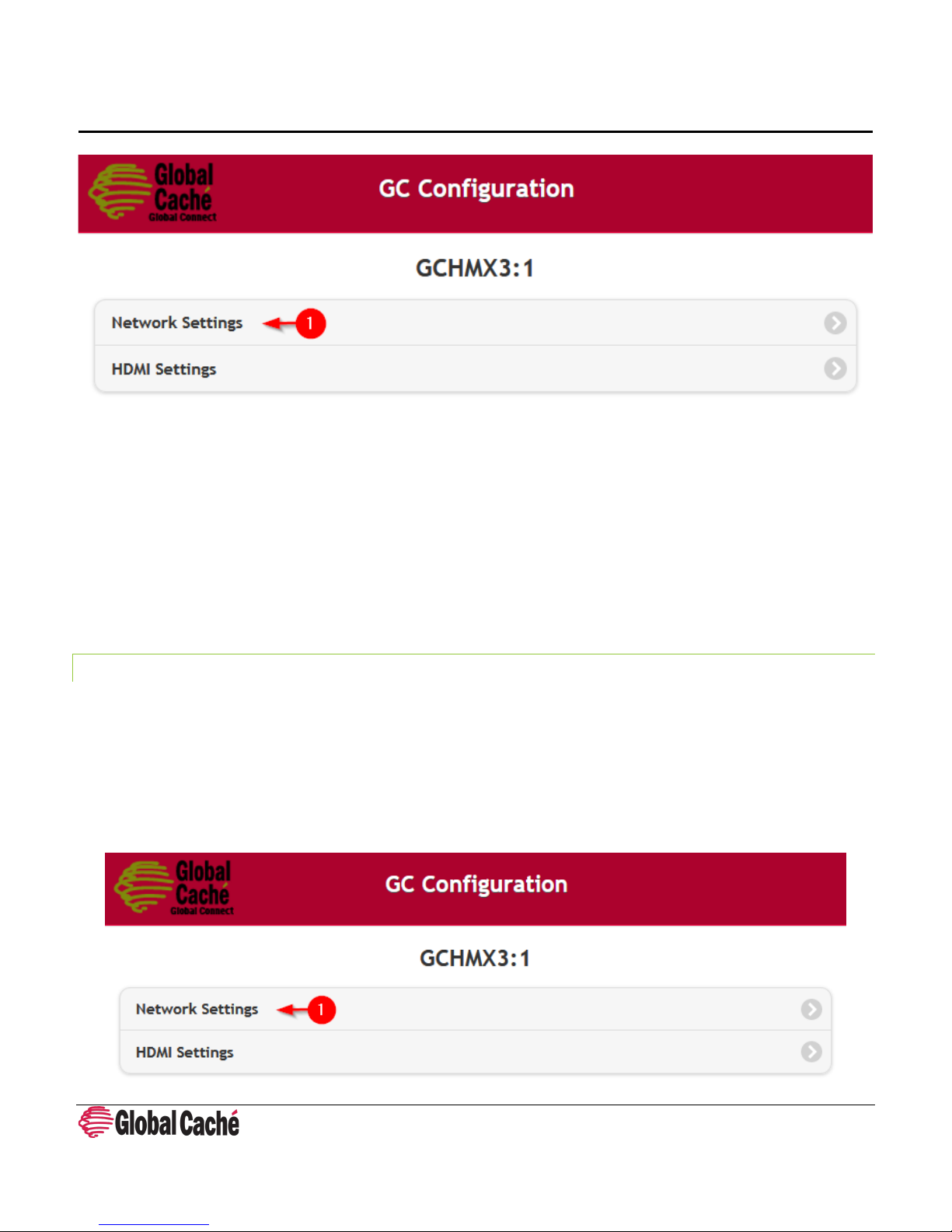
Configuration Example:
To return a static assigned unit to DHCP, navigate to the Network Settings page of the module’s configuration pages.
Global Connect User Guide 160 East California Street, PO Box 1659
Effective: January 10, 2019 Jacksonville, Oregon 97530
PN: 103118-01 ver. 1 Phone: 541-899-4800
Page 6 Fax: 541-899-4808
www.globalcache.com
Information subje ct to change withou t notice.
Page 7

Global Connect
User Guide
Change the DHCP setting from Disabled to Enabled and press Apply Changes. The module’s network name (hostname) can
optionally be changed by entering a value in the name field and pressing Apply Changes.
DHCP Reservations
The purpose of a DHCP reservation is to ensure that a networked device always receives the same IP address every time it
requests one from the DHCP server. This is important for automation devices as many control systems rely on an unchanging
IP address. While exact instructions may vary, typically DHCP reservations are made in the router and can be set somewhere
under DHCP settings.
When setting a DHCP reservation the MAC address of the module is associated with the IP address it should be assigned. This
allows the DHCP server to assign the reserved IP address every time it sees a DHCP request from the module with the MAC
address entered in the reservation.
5.3.2 STATIC IP ADDRESSES (ADVANCED)
Setting static IP address settings allows manual configuration of network settings. Static IP address assignments must be
used on networks that do not have a DHCP server. On networks that do have a DHCP server static IP settings can be used as
an alternative to a DHCP reservation, however mixing DHCP and static IP address assignments can cause issues if not
implemented properly. DHCP reservations are therefore suggested for all but advanced users.
When static IP address assignment is used it is important to keep track of what IP addresses have already been assigned on
the network. Assigning two devices or modules to the same IP address will cause an IP address conflict which will result in
Global Connect User Guide 160 East California Street, PO Box 1659
Effective: January 10, 2019 Jacksonville, Oregon 97530
PN: 103118-01 ver. 1 Phone: 541-899-4800
Page 7 Fax: 541-899-4808
www.globalcache.com
Information subje ct to change withou t notice.
Page 8

Global Connect
User Guide
loss of communication with that device. If an IP address conflict is created, or a module is assigned a non-communicable IP
address, one simple way to recover the module is to perform a factory default as explained in section 11.0.
Configuration Example:
To set a static IP address assignment, navigate to the Network Settings page of the module’s configuration pages.
Set DHCP to Disabled, and enter the desired IP address, subnet mask, gateway, and primary and secondary DNS servers. The
module’s network name (hostname) can also optionally be changed by entering a value in the Name field. After the settings
have been entered press Apply Changes to save the configuration.
Global Connect User Guide 160 East California Street, PO Box 1659
Effective: January 10, 2019 Jacksonville, Oregon 97530
PN: 103118-01 ver. 1 Phone: 541-899-4800
Page 8 Fax: 541-899-4808
www.globalcache.com
Information subje ct to change withou t notice.
Page 9

Global Connect
GCHMX3 Module Feature
Description
Ports
3 Inputs, 1 Output
Data Bandwidth
18Gbps
UHD 4K 60Hz, 4:4:4 8 bit
UHD 4K 60Hz, 4:2:0 8 bit|10 bit|12 bit
Chassis Slots Occupied
2
User Guide
6.0 GCHMX3 – HDMI 3:1 SWITCHING MODULE
The GCHMX3 module allows for network-controlled switching between 3 different sources at resolutions up to UHD 4K at
60Hz. The module also includes HDMI-CEC (Consumer Electronic Control) injection capabilities which provides easy command
and control of devices connected through HDMI. The GCHMX3 module includes support for HDCP 2.2 (High-bandwidth Digital
Content Protection), allowing for seamless use with the latest HDCP 2.2 devices.
4K Resolutions
UHD 4K 60Hz, 4:2:2 8 bit|10 bit|12 bit
6.1 CONSUMER ELECTRONIC CONTROL (CEC)
Consumer Electronic Control (CEC) is designed to allow control commands to pass over HDMI. While typically control systems
have not had access to the CEC bus, the GCHMX3 module allows access to control over CEC by allowing for injection and
reception of CEC commands. With CEC control many commands typically sent with a physical remote can be performed over
a hard-wired HDMI connection.
6.2 HDMI SWITCHING
The GCHMX3 module provides 3 in 1 out HDMI switching functionality. The module allows for switching to any one of the 3
HDMI inputs as well as turning off transmission completely from the HDMI switch. The switch also can detect whether the
connected HDMI devices are on or powered off/in standby.
Configuration Example:
To access the HDMI configuration settings, navigate to the HDMI Settings page on the unit’s configuration pages.
Global Connect User Guide 160 East California Street, PO Box 1659
Effective: January 10, 2019 Jacksonville, Oregon 97530
PN: 103118-01 ver. 1 Phone: 541-899-4800
Page 9 Fax: 541-899-4808
www.globalcache.com
Information subje ct to change withou t notice.
Page 10

Global Connect
GCIR3 Module Feature
Description
Ports
3 x IR Outputs/Sensor Inputs
Included Cables
3 x IR Emitters, 1 x IR Blaster
IR Output Frequency
20KHz – 500KHz
IR Learner Frequency
20KHz – 200KHz
Chassis Slots Occupied
1
User Guide
While the HDMI module does not require configuration of any HDMI settings, a testing interface is provided for switching the
HDMI switcher through the web interface. To switch the HDMI switch to a port, turn the output port On, then select the
desired input port and press Apply Changes. All other setup options can be configured in the chosen control software.
7.0 GCIR3 - INFRARED (IR) CONTROL MODULE
Infrared (IR) is a common control type and is commonly used for AV control, but also used in applications for climate control
systems, blinds, fans, and IP cameras. Global Connect’s GCIR3 Infrared modules can control any device that utilizes an IR
remote.
In addition to IR control the GCIR3 IR ports can be configured for Sensor Input. This allows for the use of iTach sensor cables
for sensing the presence of voltage, contact closure, or composite video.
7.1 IR TRANSMITTERS
Global Connect User Guide 160 East California Street, PO Box 1659
Effective: January 10, 2019 Jacksonville, Oregon 97530
PN: 103118-01 ver. 1 Phone: 541-899-4800
Page 10 Fax: 541-899-4808
www.globalcache.com
Information subje ct to change withou t notice.
Page 11

Global Connect
User Guide
IR Emitters:
IR emitters are short-range IR transmitters. Short-range IR transmitters are designed to physically transmit IR signals to a
single device while avoiding cross-talk with neighboring devices. Visible IR emitters, such as the emitters included with the
GCIR3 module have a range of around 1” (2.5 cm). Due to the short range of IR emitters it is important to place the IR
emitters directly on top of the IR receiver of the controlled device.
To find the IR receiver on a device look for a shiny black window in the front of the device. If the device does not have a
window, or is made of a uniform material, use a flashlight to search for the receiver. IR receivers typically are made of black
shiny plastic and are typically placed as close to the front of the device’s enclosure as possible.
IR Blasters:
IR Blasters are long-range IR transmitters. Long-range IR transmitters are designed to control devices across the room or to
control multiple devices that are near each other. The IR blaster included with the GCIR3 module is designed to transmit up
to 35 feet (10 meters).
To allow long transmission distances, IR signals using IR blasters are non-visible. Non-visible IR transmitters are not visible to
the human eye but are very visible to the IR receivers within IR controlled devices. To determine if a non-visible IR transmitter
is transmitting look at the lightpipe above the IR port on the GCIR3 module. On each IR transmission (for both emitters and
blasters), the lightpipe above the IR output will blink indicating transmission.
Configuration Example:
To access the Infrared configuration settings, navigate to the IR Settings page on the unit’s configuration pages.
If an IR blaster will be used select Blaster, otherwise select Emitter. Press Apply Changes to save the configuration. All
remaining configuration will be done in the chosen control software.
Global Connect User Guide 160 East California Street, PO Box 1659
Effective: January 10, 2019 Jacksonville, Oregon 97530
PN: 103118-01 ver. 1 Phone: 541-899-4800
Page 11 Fax: 541-899-4808
www.globalcache.com
Information subje ct to change withou t notice.
Page 12

Global Connect
User Guide
7.2 OBTAINING INFRARED (IR) CODES
Before an Infrared device can be controlled the appropriate IR codes need to be obtained. IR codes and code sets are the
control data for your IR device. Global Caché’s Control Tower (https://www.globalcache.com/controltower
), the first IR
database in the cloud, provides IR code sets. Control Tower is updated quarterly and contains IR codes for thousands of IR
devices. If IR codes for your device are not available on Control Tower Global Connect has a built in IR learner on every IR
module. iLearn is a Global Caché free utility for use learning IR codes (
https://www.globalcache.com/downloads/)
A tutorial for learning IR codes with iLearn is available on our website:
https://www.globalcache.com/support/ilearntutorial/
Information about how to use the IR database is available on the Control Tower website:
https://irdb.globalcache.com/Home/About
.
7.3 TROUBLESHOOTING IR
Confirming Transmission
When sending an IR code to a GCIR3 port the unit will respond with a completeir,... response. If sending the IR code via iTest
(http://www.globalcache.com/downloads/) this can be seen in the ASCII response field. If an error response is received
instead, then there is likely something wrong with the IR code or IR code format being used. A list of Error Codes and their
meanings is available as a chart within iTest.
In addition to the completeir response, transmission can also be visibly confirmed on the unit. A green LED near each IR port
will blink during an IR transmission. Also, if standard, visible IR emitters are used the emitter should also blink red during the
IR transmission.
Global Connect User Guide 160 East California Street, PO Box 1659
Effective: January 10, 2019 Jacksonville, Oregon 97530
PN: 103118-01 ver. 1 Phone: 541-899-4800
Page 12 Fax: 541-899-4808
www.globalcache.com
Information subje ct to change withou t notice.
Page 13

Global Connect
User Guide
Troubleshooting Reception
If an IR code is being transmitted, but the AV device is not reacting, one possibility is that the IR signal is not being received by
the AV device's IR receiver. Infrared emitters are short range IR transmitters. As a result, they must be physically placed
directly on top of the IR receiver for the receiver to receive a strong enough signal to respond.
If using an IR blaster, it is also important to note that while IR blasters send strong signals, they are directional. While the
signal may reflect off surfaces in the environment, to be received when transmitting from long distances, or when
troubleshooting the blaster should be pointed directly at the AV device’s receiver.
For more information about the differences between IR transmitters please see section 7.1 IR Transmitters.
IR code Issues
Getting good IR codes is often the most difficult portion of any IR control project. Fortunately, Control Tower
(https://www.globalcache.com/controltower), Global Caché’s IR database in the cloud, makes this a simple process for the
majority of common AV equipment. If the AV device needed is not present in Control Tower it is often beneficial to try any
similar codesets by the same manufacturer, as often manufacturers re-use IR codes between device models. If those codes
fail, or no similar devices are available then the IR codes will either need to be learned using
from a 3rd party source (in which case they are often in Pronto Hex format, which can be converted to GC format using
iConvert – https://www.globalcache.com/downloads).
iLearn (section 7.2) or obtained
IR code repeats
One of the simplest changes that can affect whether an IR code works is the repeat value. The repeat value defines how
many times the IR code is transmitted. The repeat value can be set as a learning parameter in iLearn, or can be edited directly
by changing the following <repeat> value in this example IR code:
sendir,<module>:<connector>,1,38000,<repeat>,...The most common manufacturer that requires repeats is Sony. For Sony
and other manufacturers that require repeats in the IR code the suggested value is 3.
RF Remotes
AV devices commonly utilize IR remotes for control. However, there are some devices that utilize RF remotes which are not
controllable or learnable via IR. Because IR uses line of sight communication, a simple way to determine if a remote utilizes
IR or RF is to perform a line of sight test. To do this, point the remote at the device and send a command that will create a
noticeable response (such as power on/off). The device should react accordingly. Now, cover the front of the remote
completely using your hand and repeat the test. If the command still completes successfully then the remote likely utilizes RF
and is not an IR remote. If the command does not react to the command then the device uses IR.
Note: A small handful of devices that utilize RF remotes also have IR functionality as well. To determine if an RF device has IR
capabilities refer to the product manual or contact the product manufacturer.
Global Connect User Guide 160 East California Street, PO Box 1659
Effective: January 10, 2019 Jacksonville, Oregon 97530
PN: 103118-01 ver. 1 Phone: 541-899-4800
Page 13 Fax: 541-899-4808
www.globalcache.com
Information subje ct to change withou t notice.
Page 14
Global Connect
GCSL232 Module Feature
Description
Ports
1 x Male DB9
Baud Rate
300-115200 baud
Flow Control
Hardware, None
Parity
None, Even, or Odd
Data Bits
8
Stop Bits
1, or 2
Chassis Slots Occupied
1
User Guide
8.0 GCSL232 – RS232 SERIAL CONTROL MODULE
RS232 is a common serial protocol that is utilized on devices ranging from TVs and amplifiers, to security panels and pool
controllers. The GCSL232 module connects RS232 devices to a network and serial devices. The bidirectional GCSL232 module
connects RS232 devices to a network and includes an easy to use, highly configurable web interface.
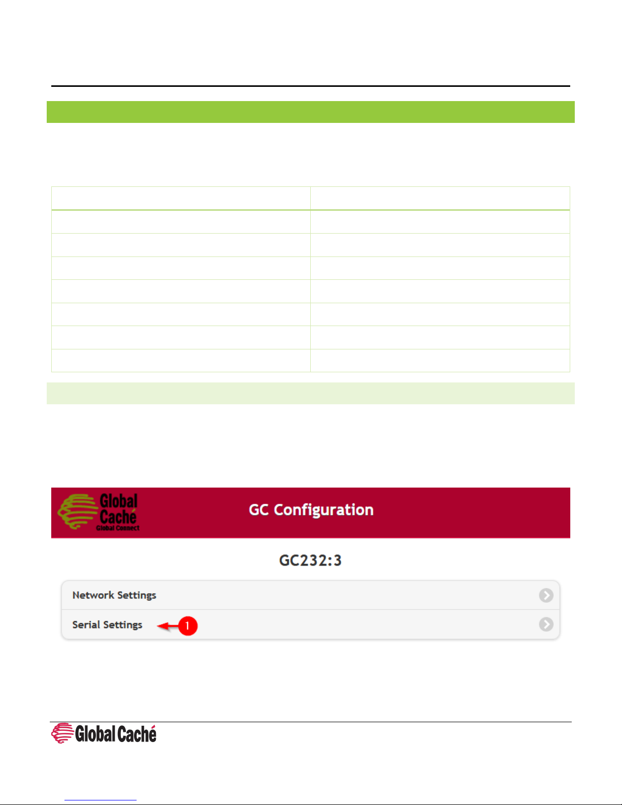
8.1 SERIAL CONFIGURATION
The GCSL232 module must be configured with the serial settings of the device that will be controlled.
Configuration Example:
To access the serial configuration settings, navigate to the Serial Settings page on the unit’s configuration pages.
On the Serial Settings page, select the desired baud rate, Flow Control, Parity, and Stop Bits values. Click Apply Changes to
save the configuration. All remaining configuration will be done in the chosen control software.
Global Connect User Guide 160 East California Street, PO Box 1659
Effective: January 10, 2019 Jacksonville, Oregon 97530
PN: 103118-01 ver. 1 Phone: 541-899-4800
Page 14 Fax: 541-899-4808
www.globalcache.com
Information subje ct to change withou t notice.
Page 15

Global Connect
User Guide
8.2 DB9 PINOUT
The DB9 connector is a common connector for RS232 interfaces. Typically, RS232 devices will either have a male or female
DB9 connector. The devices with male connectors are usually known as DTE (Data Terminal Equipment). Devices with the
female connector are known as DCE (Data Communications Equipment). The GCSL232 has a male (DTE) connector and its
pinout is shown below.
Global Connect User Guide 160 East California Street, PO Box 1659
Effective: January 10, 2019 Jacksonville, Oregon 97530
PN: 103118-01 ver. 1 Phone: 541-899-4800
Page 15 Fax: 541-899-4808
www.globalcache.com
Information subje ct to change withou t notice.
Page 16

Global Connect
Pin Number
Description
1
No Connection
2
Receive (Rx)
3
Transmit (Tx)
4
Data Terminal Ready (DTR)
5
Ground
6
No Connection
7
Request to Send (RTS)
8
Clear to Send (CTS)
9
No Connection
Gender of connected device
Cable
Male
Female to Female, Null-modem/Crossover Cable*
Female
Female to Male, Straight-Through Cable*
User Guide
When using Straight-Through DB9 to 3.5mm jack converter cables the typical pinout will be Rx, Tx, Ground on the Tip, Ring,
and Sleeve of the 3.5mm jack respectively. Both Straight-Through and Null-Modem cables exist for DB9 to 3.5mm jack cables
as well (Section 8.3).
8.3 STRAIGHT-THROUGH AND NULL-MODEM CABLES
When connecting the GCSL232 to a serial device the correct cable must be used. The following table lists the correct cable
type that should be used when connecting the GCSL232 to serial devices with the DB9 connector.
*Note: The above table lists the suggested cable based on the widely and most prominent accepted pinout for DB9 serial
devices. Though rare, some manufacturers do not follow this pinout. For those cases, a different cable may be needed.
9.0 GCRL3A – RELAY CONTROL MODULE (6 RELAYS)
Relays are some of the most basic forms of control. Contact closure relay uses a simple dry contact to trigger a relay event
and is one of the most basic forms of control. Despite their simplicity, the ability to provide power or a dry contact makes
them suitable for controlling devices through powering them on and off, or by providing control input to voltage inputs or dry
contact inputs.
Global Connect User Guide 160 East California Street, PO Box 1659
Effective: January 10, 2019 Jacksonville, Oregon 97530
PN: 103118-01 ver. 1 Phone: 541-899-4800
Page 16 Fax: 541-899-4808
www.globalcache.com
Information subje ct to change withou t notice.
Page 17

Global Connect
GCSL232 Module Feature
Description
Ports
6 x SPST Relays
Maximum Rating
250V AC, 30V DC, or 6 Amps
Compatible Wire Gauges (Connector)
14-30 AWG
Relay Type
Normally Open (NO)
Chassis Slots Occupied
2
User Guide
Configuration example:
To access the relay configuration settings, navigate to the Relay Settings page on the unit’s configuration pages.
While the GCRL3A module does not require configuration of any relay settings, a testing interface is provided through the
web interface for switching the relays. To switch a relay, press the desired ports toggle to turn it On or Off. The relay will
change to the set state. All remaining configuration will be done in the chosen control software.
Global Connect User Guide 160 East California Street, PO Box 1659
Effective: January 10, 2019 Jacksonville, Oregon 97530
PN: 103118-01 ver. 1 Phone: 541-899-4800
Page 17 Fax: 541-899-4808
www.globalcache.com
Information subje ct to change withou t notice.
Page 18

Global Connect
User Guide
9.1 TROUBLESHOOTING RELAYS
Confirming Relay Actuation
To confirm that the unit has received the relay state change, look at the lightpipe above the related relay port. When
changing the relay, the lightpipe will turn on when the relay is turned on and off when the relay is turned off.
To confirm that the relay is physically closing or opening a continuity test can be used.* Disconnect all wires from the relay
terminal blocks. Using a multimeter set the meter to the continuity setting. Touch one probe to each terminal corresponding
to the relay that is being tested. Using the web interface, or the control software, switch the relay to on and check for
continuity. Once confirmed, switch the relay to Off and confirm that there is no longer continuity.
*Note: This test uses a multimeter with a continuity test function. The test should never be performed with voltage applied
to any of the terminal blocks on the GCRL3A module.
Global Connect User Guide 160 East California Street, PO Box 1659
Effective: January 10, 2019 Jacksonville, Oregon 97530
PN: 103118-01 ver. 1 Phone: 541-899-4800
Page 18 Fax: 541-899-4808
www.globalcache.com
Information subje ct to change withou t notice.
Page 19

Global Connect
GCRPI Module Feature
Description
1 x RJ45 Ethernet
1 x Full-size HDMI
1 x GPIO Header
Built in WiFi and Bluetooth
Chassis Slots Occupied
3
User Guide
10.0 GCRPI – RASPBERRY PI MODULE
The GCRPI module is an optional Raspberry Pi 3B or 3B+ mount for rack mounted Global Connect units. The Raspberry Pi
(RPI) is an inexpensive mini-computer that can be used to perform most tasks a typical computer can. Developed by the
Raspberry Pi foundation to help teach programming, the Raspberry Pi has seen widespread support in that and a growing
number of other industries.
Rack Accessible Ports
Other Ports
4 x USB 2.0 Ports
1 x CSI Camera Port
1 x DSI Display Port
1 x 4-Pole Stereo Output and Composite Video Port
1 x Micro SD Port
For more information on the Raspberry Pi 3 specifications please visit the Raspberry Pi Foundation’s web site
(https://www.raspberrypi.org/).
Configuration of the Raspberry Pi module is based on the software image being run. Please contact the provider of the
Raspberry Pi control software being used for configuration instructions.
10.1 THE RASPBERRY PI IN AUTOMATION
The Raspberry Pi can run several different Operating Systems (OS), including Linux OSes, and a Windows IoT core OS. This
flexibility allows our control partners to develop software that runs on the RPI. To find Global Caché partners whose software
runs on the Raspberry Pi please visit Global Caché’s Partner Control Apps page:
https://www.globalcache.com/partners/control-apps/
Units that include the Raspberry Pi and SD card will ship with the ControlPi image offered here:
https://gitlab.com/patrickmurray/controlpi
A use of the Raspberry Pi is to provide cloud connectivity. As a computer the Raspberry Pi can run software for connecting
Global Connect modules to any number of cloud-based IoT platforms. In this capacity the Raspberry Pi can provide secure
rd
connections to our partner’s or 3
Global Connect User Guide 160 East California Street, PO Box 1659
Effective: January 10, 2019 Jacksonville, Oregon 97530
PN: 103118-01 ver. 1 Phone: 541-899-4800
Page 19 Fax: 541-899-4808
www.globalcache.com
party cloud servers.
Information subje ct to change withou t notice.
Page 20

Global Connect
User Guide
The Raspberry Pi can also run control software. With control software running on the Pi, the Raspberry Pi can become the
controller for the automation system and run automations, macros, and triggers depending on the needs of the system.
11.0 FACTORY DEFAULT
To factory default a Global Connect unit locate the first or left-most lightpipe on each module. Depress the lightpipe for
approximately 10 seconds. After 10 seconds all lightpipes on the module will begin rapidly indicating the unit is ready to
reset. Release the lightpipe to complete the factory default. Due to the modular nature of the Global Connect product line
each module is individually factory defaulted.
Global Connect User Guide 160 East California Street, PO Box 1659
Effective: January 10, 2019 Jacksonville, Oregon 97530
PN: 103118-01 ver. 1 Phone: 541-899-4800
Page 20 Fax: 541-899-4808
www.globalcache.com
Information subje ct to change withou t notice.
 Loading...