

Page 1

e GC-1 00 -1 2 an d GC -10 0-1 8 Network Adapters
connect diverse and previously unconnected devices
and appliances in a network-based home, school or
business. Using many com monly needed controls and
sensor inputs in one box, the GC-100 provides an
easy way for controlling real-world devices, reducing
the time and complexity of an installation by
eliminating piggybacked components and multiple
power supplies. By simply sending commands
over the network, your audio/visual equipment
is turned to the proper volume by infrared (IR),
shades are lowered with relays, and your favorite
DVD is selected through serial communications;
and all started with the push of a button. As a
result of using open standards (for example, TCP/
IP), any networked device, such as your PC, can
send and retrieve GC-100 data. With the GC-100,
a variety of devices can be connected to control and
monitor the environment over a network or even the
Internet.
e GC-100 is designed to work with many of
the popular control software packages. ese
packages contain software drivers needed for the
proper operation of the GC-100, as well as, an easyto-use interface for conguring your automated
environment. It is required that such a package be
employed when using the GC-100 product family.
Getti ng star ted is simple. A ll it requires is c onnecting
power, conguring the unit, and attaching cables.
is guide provides a step-by-step method to get you
up and running quickly and easily with a discussion
of each connector’s pin out, web page conguration,
and specication.
voltage is ±24V, with an “on” indication for voltages
greater than 2.5V and “o ” when less than 0.8V with an
input impedance of ~100KΩ.
When selected, IR commands can be transmitted
without their carrier frequency, as waveform envelopes.
is is used for direct audio/video inputs, such as
Control-S, or for modulating RF signals.
When congured as GC-BL2 Blaster mode, the
connector is to be used with a GC-BL2 IR Blaster. is
mode does not support IR blasters provided by other
manufacturers.
Sensor Notications are used to automatically signal
changes in sensor state. Any connector congured as an
input with auto-notify will send notications. e state
of a sensor can also be polled at any time.
Relays are used for switching devices on and o. e
contacts are “norma lly open” and rated for 500mA at 2 4V
(DC or AC). e mating connectors use screw terminals
to attach wiring. Relay contacts are non-directional, and
wires may be connected in any order.
Relay contacts are protected against transients greater
than 150 volts caused by switching inductive loads, such
as motor and relays. e transient voltage suppressor
(TVS) eliminates contact arching by clipping positive
and negative voltage spikes that exceed 150 volts.
Global Caché, Inc. - 160 East California Street - P O Box 1659
Jacksonville, Oregon 97530 - Phone (541) 899-4 800
Fax (541) 899-48 08 - www.globalcache.com
Support: support@globalcache.com
Copyrig ht ©2008 Global Cac hé, Inc. All right s reserved.
PN: 030127-02 ver.13/Information subject to change without notice.
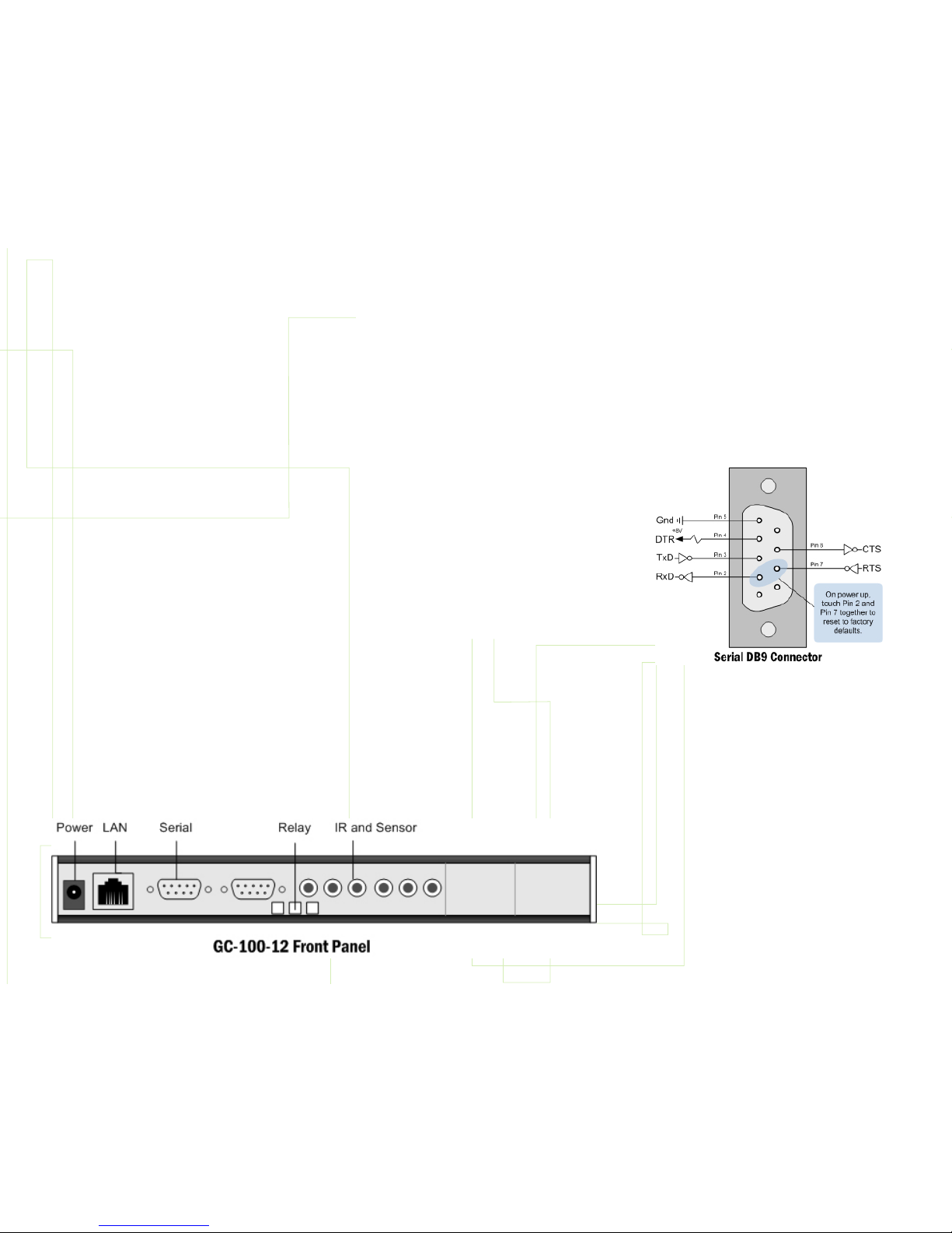
e serial device attaching to the GC-100 will likely
employ a 9 or 25 pin DB connector. Following is the
standard wiring conguration for a serial cable. It is
not guaranteed that the standard has been followed,
but it is a good starting place. For example, when
connecting the GC-100 male serial connector to A/V
equipment that also uses a male DB9 connector pins
2 and 3 would need to crossover. Pin 2 on the GC100 would connect to pin 3 on the A/V device.
GC -10 0
DB9 DB9 DB9 DB25 DB25
male male female male female
Data
RxD 2 3 2 3 2
TxD 3 2 3 2 3
Gnd 5 5 5 7 7
Data Flow Control
RTS 7 8 7 5 4
CTS 8 7 8 4 5
Modem Controls
DTR 4 6 4 6 20
DSR 6 ignored by the GC-100
IR output and sensor input share a common
connector and indicator on the GC-100. Each 3.5mm
audio connector is independently congured using
the internal web pages or the GC-100 Discovery &
Conguration Utility available for download from
www.globalcache.com. Each connector has three
contacts congured as either an infrared (IR) output,
Control-S output (IR/no car rier), GC-BL2 IR Blaster
output, or sensor input, as shown below.
When cong ured as an output the indicator will blink
as an IR command is transmitted. When functioning
as a sensor, the indicator is “on” when a positive input
or no connection is present. e maximum sensor
input
Global Caché
GC-100-12/18
Network Adapter
Quick Start Guide
This dev ice complies wit h Part 15 of FCC ru les and with ICES003 of Indust ry Canada. O peration i s subject to the following two
conditions:
(1) This device may not caus e harm ful int erference, and
(2) This device must accept any i nterference received, includi ng
interfe rence tha t may cause undesired op eration.
Page 2
e GC-100 Discovery and Conguration Utility is
available for download from the support section on
our website (www.globalcache.com). Once installed,
the application will listen for the GC-100 on the
network and display it in a list. It may take up to 60
seconds for the all GC-100s on the network to be
listed. Conguration settings can ve view and edited
by highlighting a GC-100 in the list and pressing the
Congure button.
Power is supplied by an AC wall adapter rated for 9V
to 18V DC@300mA. Shortly after applying power all
the IR indicators will momentarily turn on then o
signifying completion of the self-test. e GC-100 is
ready for operation after the power (PWR) indicator
is on.
LAN connection is used for all communication over
the network and for conguring the GC-100. e
GC-100 is set to support DHCP by default. To locate
the GC-100 on the network and determine its IP
address, download and install the GC-100 Discovery
& Conguration Utility from www.globalcache.com.
Once installed, the utility provides a list of GC-100s
on the network and allows the user to change the
settings of those found.
In most network environments, the GC-100 can also
be accessed by na me. e network name of a GC-100 is
“GC100_XXXXXXXXXXXX_GlobalCache” where
the Xs are the 12 character MAC address printed on
the bottom of the GC-100. For example, if the MAC
address was “000C1E012345” then the GC-100
network name would be “GC100_000C1E012345_
GlobalCache.”
If using a crossover cable connected directly to a
computer, or if a DHCP server is not avai lable, the GC100 will use the default IP address of 192.168.1.70.
e PC must also be on the same network with an
address such as 192.168.1.102. e “LINK” indicator
on the LAN connector will light when the cable is
plugged in properly. After establishing a link, the
GC-100’s web pages are accessible from a browser by
entering its IP address.
A suitable static IP address can also be entered for your
network environment, making sure the GC-100’s IP
address is outside the net work’s DHCP partition, if
DHCP is used. In addition the default gate way address
and subnet mask will need to be set before installing
the GC-100. Once the GC-100 is on your network,
further conguration can be accomplished through the
new IP address.
Except for serial, all data commands are sent over TCP/
IP Port 4998. is includes infrared, sensor, and relay
commands. Each serial connection has a unique port
number for communication, starting with Port 4999
for serial connector 1, Port 5000 for serial connector
2, and so on.
Factory defaults can be set during power up by
connecting pins 7 and 2 on connector SERIAL 1 with
a wrap back connector or a at bladed screw driver.
(Refer to the Serial DB9 Connector diagram for pin
locations.) IR indicator 1 will blink on, then all the IR
indicator lights will blink on, then all of them will go
o. is indicates the GC-100 has been set to factory
defaults, including Conguration Lock, which defaults
to disabled.
Web pag es are used to congure the GC-100 for proper
operation in a particular environment. Parameters are
selected by pull down menus and put into eect after
executing “Apply.” e GC-100 resets, blinking all
indicators on then o, to complete the update.
Serial communication utilizes a male (9 pin) DB9
connector with active signals on the pins shown in the
diagram. Unfortunately, serial standards are
not always adhered to, and special attention must
be given when connecting serial cables. For proper
serial communication cable conguration, baud rate
(communication speed) parity, and ow control must
be correct. At a minimum, to send and receive serial
data TxD, RxD, and Gnd must be connected to the
other serial device. ese signal locations will depend
on the mating connector’s type and gender. Typically,
communications can be established by a trial and
error method of swapping the TxD and RxD
lines. Incorrect wiring will not harm serial drivers.
Also, ow control must be disabled or asserted for
communications to start. If erroneous characters are
transmitted, it is usually an indication of an incorrect
baud rate setting.
ere are two types of ow control: RTS/CTS for
data ow and DTR /DSR for modem control. e
GC-100 does not use modem ow control and will
always assert the DTR line and ignore DSR. When
data ow control is used, the GC-100 will stop
its transmission when its CTS signal is asserted by
the other device. When receiving data the GC-100
may assert RTS to signal the other device to stop
its transmission. In a typical control environment,
serial devices usually communicate with short and
infrequent commands. Hence, some serial devices
may not have ow control signals. is is usually not
a concern, since a serial input buer is much larger
(256 bytes) than the transmitted data commands.
In these cases, the GC-100 ow control should be
disabled. However, to avoid potential character loss,
it is a good rule to use ow control when it is available
on serial devices. e GC-100 performs ow control
by asserting RTS when the input buer goes beyond
192 bytes, and de-asserting RTS when it falls below
64 bytes. In either case, the GC-100 records all
serial buer overows and maintains a count on the
Network web page.
 Loading...