

Page 1
e GC-100-06 Network Adapter connects
diverse and previously unconnected devices and
appliances in a network-based home, school
or business. Using many commonly needed
controls and sensor inputs in one box, the GC100 provides an easy way for controlling realworld devices, reducing the time and complexity
of an installation by eliminating piggybacked
components and multiple power supplies. By
simply sending commands over the network, your
audio/visual equipment is turned to the proper
volume by infrared (IR), shades are lowered with
relays (on the GC-100-12), and your favorite
DVD is selected through serial communications;
and all started with the push of a button. As a
result of using open standards TCP/IP, any
networked device, such as your PC, can send
and retrieve GC-100 data. With the GC-100, a
variety of devices can be connected to control and
monitor the environment over a network or even
the Internet.
e GC-100 is designed to work with many of
the popular control software packages. ese
packages contain the drivers needed for the proper
operation of the GC-100, as well as, an easy-touse interface for configuring your automated
environment. It is required that such a package
be employed when using the GC-100 product
family.
When selected, IR commands can be transmitted
without their carrier frequency, as waveform envelopes.
is is used for direct audio/video inputs, such as
Control-S, or for modulating RF signals.
When configured in GC-BL2 Blaster mode, the
connector is to be used with a GC-BL2 IR Blaster. is
mode supports the Global Caché GC-BL2 IR Blaster
on ly.
Sensor Notifications are used to automatically signal
changes in sensor state. Any connector configured as an
input with auto-notify will send notifications. e state
of a sensor can also be polled at any time.
Global Caché, Inc.
160 East California Street
PO Box 1659
Jacksonville, Oregon 97530
Phone (541) 899-4800
Fax (541) 899-4808
www.globalcache.com
Support: support@globalcache.com
Sales: sales@globalcache.com
General Info: info@globalcache.com
Copyright ©2008 Global Caché, Inc . All rights reserved.
PN: 030127-02 ver.12/Information subject to change without
notice.
GC -100
DB9 DB9 DB9 DB25 DB25
male male female male female
Data
RxD 2 3 2 3 2
TxD 3 2 3 2 3
Gnd 5 5 5 7 7
Data Flow Control
RTS 7 8 7 5 4
CTS 8 7 8 4 5
Modem Controls
DTR 4 6 4 6 20
DSR 6 ignored by the GC-100
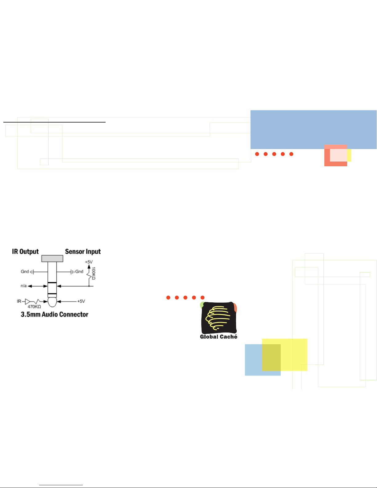
IR output and sensor input share a common
connector and indicator on the GC-100. Each 3.5mm
audio connector is independently configured using
the internal web pages or the GC-100 Discovery &
Configuration Utility available for download from
www.globalcache.com. Each connector has three
contacts configured as either an infrared (IR) output,
Control-S output (IR/no carrier), GC-BL2 IR Blaster
output, or sensor input, as shown below.
When configured as an output the indicator will blink
as an IR command is transmitted. When functioning
as a sensor, the indicator is “on” when a positive input
or no connection is present. e maximum sensor
input voltage is ±24V, with an “on” indication for
voltages greater than 2.5V and “off” when less than
0.8V with an input impedance of ~100KΩ.
Global Caché
GC-100-06
Network Adapter
Quick Start Guide
This dev ice complies with Pa rt 15 of FCC rules and w ith ICES003 of Indust ry Cana da. Opera tion is subject to t he following two
conditions:
(1) This device may not caus e harmf ul interfe rence, and
(2) This device must accept any int erference received, includ ing
interfe rence that may cause undesired operation.
Page 2
Getting started is simple. All it requires is connecting
power, configuring the unit, and attaching cables.
is guide provides a step-by-step method to get you
up and running quickly and easily with a discussion of
each connector's pin out, web page configuration, and
specification.
Power is supplied by an AC wall adapter rated for 9V
to 18V DC@300mA. Shortly after applying power, all
the IR indicators will momentarily turn on, then off,
signifying completion of the self-test. e GC-100 is
ready for operation after the power (PWR) indicator
is on.
LAN connection is used for all communication over
the network and for configuring the GC-100. e
GC-100 is set to support DHCP by default. To locate
the GC-100 on the network and determine its IP
address, download and install the GC-100 Discovery
& Configuration Utility from w ww.globalcache.com.
Once installed, the utility provides a list of GC-100s
on the network and allows the user to change the
settings of those found.
In most network environments, the GC-100 can also
be accessed by name. e network name of a GC-100 is
“GC100_XX XXXXX XXXXX _GlobalCache” where
the Xs are the 12 character MAC address printed on
the bottom of the GC-100. For example, if the MAC
address was “000C1E012345” then the GC-100
network name would be “GC100_000C1E012345_
GlobalCache.”
If using a crossover cable connected directly to a
computer, or if a DHCP server is not available, the GC100 will use the default IP address of 192.168.1.70.
e PC must also be on the same network with an
address such as 192.168.1.102. e "LINK" indicator
on the LAN connector will light when the cable is
plugged in properly. After establishing a link, the
GC-100's web pages are accessible from a browser by
entering its IP address.
A suitable static IP address can also be entered for your
network environment, making sure the GC-100’s IP
address is outside the network’s DHCP partition, if
DHCP is used. In addition the default gate way address
and subnet mask will need to be set before installing
the GC-100. Once the GC-100 is on your network,
further configuration can be accomplished through the
new IP address.
Except for serial, all data commands are sent over TCP/
IP Port 4998. is includes infrared, sensor, and relay
commands. Each serial connection has a unique port
number for communication, starting with Port 4999
for serial connector 1, Port 5000 for serial connector
2, and so on.
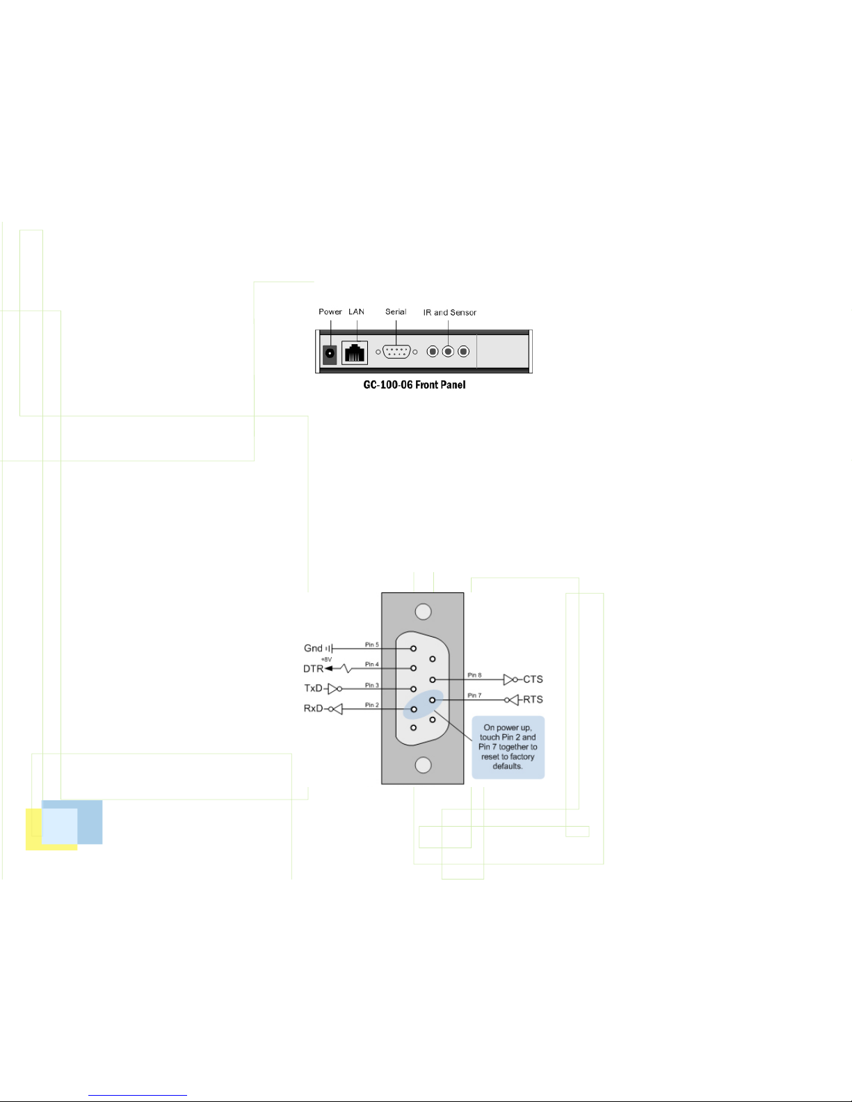
Factory defaults can be set during power up by
connecting pins 7 and 2 on connector SERIAL 1 with
a wrap back connector or a flat bladed screw driver.
(Refer to the Serial DB9 Connector diagram for pin
locations.) IR indicator 1 will blink on, then all the IR
indicator lights will blink on, then all of them will go
off. is indicates the GC-100 has been set to factory
defaults, including Configuration Lock, which defaults
to disabled.
Web pages are used to configure the GC-100 for proper
operation in a particular environment. Parameters are
selected by pull down menus and put into effect after
executing “Apply.” e GC-100 resets, blinking all
indicators on then off, to complete the update.
Serial communication utilizes a male (9 pin) DB9
connector with active signals on the pins shown in
the diagram. Unfortunately, serial standards are
not always adhered to, and special attention must
be given when connecting serial cables. For proper
serial communication cable configuration, baud
rate (communication speed) parity, and flow control
must be correct. At a minimum, to send and receive
serial data TxD, RxD, and Gnd must be connected
to the other serial device. ese signal locations will
depend on the mating connector’s type and gender.
Typically, communications can be established by a
trial and error method of swapping the TxD and RxD
lines. Incorrect wiring will not harm serial drivers.
Also, flow control must be disabled or asserted for
communications to start. If erroneous characters are
transmitted, it is usually an indication of an incorrect
baud rate setting.
ere are two types of flow control: RTS/CTS for
data flow and DTR/DSR for modem control. e
GC-100 does not use modem flow control and will
always assert the DTR line and ignore DSR. When
data flow control is used, the GC-100 will stop its
transmission when its CTS signal is asserted by
the other device. When receiving data the GC-100
may assert RTS to signal the other device to stop
its transmission. In a typical control environment,
serial devices usually communicate with short and
infrequent commands. Hence, some serial devices
may not have flow control signals. is is usually not
a concern, since a serial input buffer is much larger
(256 bytes) than the transmitted data commands.
In these cases, the GC-100 flow control should be
disabled. However, to avoid potential character loss,
it is a good rule to use flow control when it is available
on serial devices. e GC-100 performs flow control
by asserting RTS when the input buffer goes beyond
192 bytes, and de-asserting RTS when it falls below
64 bytes. In either case, the GC-100 records all
serial buffer overflows and maintains a count on the
Network web page.
e serial device attaching to the GC-100 will likely
employ a 9 or 25 pin DB connector. Following is the
standard wiring configuration for a serial cable. It is
not guaranteed that the standard has been followed,
but it is a good starting place. For example, when
connecting the GC-100 male serial connector to
A/V equipment that also uses a male DB9 connector
pins 2 and 3 would need to crossover. Pin 2 on the
GC-100 would connect to pin 3 on the A/V device.
 Loading...