

Global American Mini-ITX 2807638 Product Manual

Product Guide
Mini-ITX Motherboard 2807638
Version 1.0

Copyrights
This manual is copyrighted and all rights are reserved. It does not allow any non authorization in
copied, photocopied, translated or reproduced to any electronic or machine readable form in
whole or in part without prior written consent from the manufacturer.
In general, the manufacturer will not be liable for any direct, indirect, special, incidental or
consequential damages arising from the use of inability to use the product or documentation, even
if advised of the possibility of such damages. The manufacturer keeps the rights in the subject to
change the contents of this manual without prior notices in order to improve the function design,
performance, quality and reliability. The author assumes no responsibility for any errors or
omissions, which may appear in this manual, nor does it make a commitment to update the
information contained herein.
Trademarks
Intel is a registered trademark of Intel Corporation.
Award is a registered trademark of Award Software, Inc.
All other trademarks, products and or product's name mentioned herein are mentioned for
identification purposes only, and may be trademarks and/or registered trademarks of their
respective companies or owners.

Revision History
Revision Revision History Date
-001 First release of the Mini-ITX Motherboard 2807638 Product Guide March 2007
Preface
This Product Guide gives information about board layout, component installation, and
regulatory requirements for Mini-ITX Motherboard 2807638.
Intended Audience
The Product Guide is intended for technically qualified personnel. It is not intended for
general audiences.
Intended Uses
All Mini-ITX motherboards are evaluated as Information Technology Equipment (I.T.E.)
for use in personal computers (PC) for installation in homes, offices, schools, computer
rooms, and similar locations. The suitability of this product for other PC or embedded
non-PC applications or other environments, such as medical, industrial, alarm systems,
test equipment, etc. may not be supported without further evaluation.
Document Organization
The chapters in this Product Guide are arranged as follows:
1 Board Features: a summary of product features
2 Installing and Replacing Board Components: instructions on how to install
the Board and other hardware components
B Regulatory
Compliance: safety and EMC regulations and product certifications
Conventions
The following conventions are used in this manual:
CAUTION
Cautions warn the user about how to prevent damage to hardware or loss of data.
NOTE
Notes call attention to important information.
iii
Mini-ITX Motherboard 2807638 Product Guide
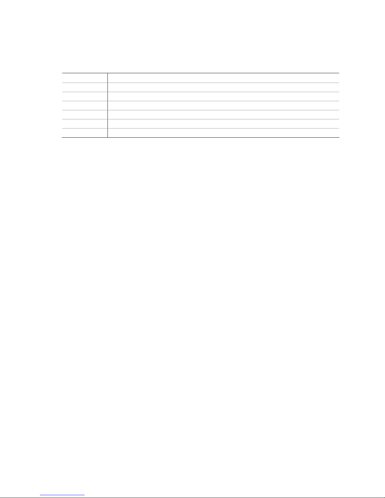
Terminology
The table below gives descriptions to some common terms used in the product guide.
Term Description
GB Gigabyte (1,073,741,824 bytes)
GHz Gigahertz (one billion hertz)
KB Kilobyte (1024 bytes)
MB Megabyte (1,048,576 bytes)
Mbit Megabit (1,048,576 bits)
MHz Megahertz (one million hertz)
Box Contents
• Mini-ITX Motherboard
• I/O shield
• One ATA-66/100 cable
• Quick Reference Guide
• Configuration and safety labels
iv

Contents
1 Mini-ITX Motherboard Features
Supported Operating Systems .............................................................................. 10
Board Components.............................................................................................. 11
Processor ...........................................................................................................13
Main Memory......................................................................................................13
Chipset ..............................................................................................................14
Graphics Subsystem ............................................................................................ 14
Audio Subsystem ................................................................................................ 14
Input/Output (I/O) Controller ............................................................................... 15
LAN Subsystem................................................................................................... 15
RJ-45 LAN Connector LEDs ...........................................................................16
Hi-Speed USB 2.0 Support ...................................................................................17
Enhanced IDE Interface ....................................................................................... 17
Expandability......................................................................................................17
BIOS .................................................................................................................17
IDE Auto Configuration................................................................................. 17
PCI Auto Configuration ................................................................................. 18
Security Passwords ...................................................................................... 18
Power Management Features ................................................................................ 18
ACPI .......................................................................................................... 18
Hardware Support ....................................................................................... 19
Power Connectors ................................................................................ 19
Fan Headers ........................................................................................19
LAN Wake Capabilities ..........................................................................20
Wake from USB ................................................................................... 20
Wake from PS/2 Keyboard/Mouse .......................................................... 20
PME# Wakeup Support ......................................................................... 20
Battery ..............................................................................................................20
Real-Time Clock .................................................................................................. 20
2 Installing and Replacing Mini-ITX Motherboard Components
Before You Begin................................................................................................. 21
Installation Precautions........................................................................................ 22
Prevent Power Supply Overload .....................................................................22
Observe Safety and Regulatory Requirements ................................................. 22
Installing the I/O Shield ....................................................................................... 23
Installing and Removing the Board........................................................................ 24
Installing and Removing Memory ..........................................................................25
Installing DIMMs.......................................................................................... 25
Removing DIMMs......................................................................................... 27
Connecting the IDE Cable..................................................................................... 27
Connecting Internal Headers ................................................................................ 29
Installing a Front Panel Audio Solution ...........................................................30
Connecting Hi-Speed USB 2.0 Headers...........................................................31
Connecting the Front Panel Header ................................................................ 31
Connecting the Chassis Fan .................................................................................. 32
Connecting Supply Power Cables ...........................................................................33
v

Mni-ITX Motherboard 2807638 Product Guide
Setting the Board Jumpers ...................................................................................34
Front Panel Audio Header/Jumper Block .........................................................34
BIOS Configuration Jumper........................................................................... 35
Clearing Passwords ...................................................................................... 36
Replacing the Battery ..........................................................................................37
A Regulatory Compliance
Safety Regulations ..............................................................................................42
Place Battery Marking ..................................................................................42
vi

Contents
Figures
1. Mini-ITX Motherboard 2807638 Components..................................................... 11
2. Back Panel Audio Connectors .......................................................................... 15
3. LAN Connector LEDs ......................................................................................16
4. Location of the Standby Power Indicator........................................................... 19
5. Installing the I/O Shield ................................................................................. 23
6. Board Mounting Screw Holes........................................................................... 24
7. Use DDR DIMMs ............................................................................................25
8. Installing a DIMM ..........................................................................................26
9. Connecting the IDE Cable ............................................................................... 28
10. Internal Headers ...........................................................................................29
11. Location of the Chassis Fan Header..................................................................32
12. Connecting a 2 x 10 or 2 x 12 Power Supply Cable ............................................33
13. Board Jumpers.............................................................................................. 34
14. Removing the Battery .................................................................................... 41
Tables
1. Feature Summary ............................................................................................9
2. Mini-ITX Motherboard Components................................................................... 12
3. RJ-45 10/100 Ethernet LAN Connector LEDs ..................................................... 16
4. Front Panel Audio Header Signal Names ...........................................................30
5. Hi-Speed USB 2.0 Header Signal Names........................................................... 31
6. Front Panel Header Signal Names .................................................................... 31
7. Front Panel Audio Header/Jumper Block ...........................................................35
8. Jumper Settings for the BIOS Setup Program Modes .......................................... 35
11. Safety Regulations......................................................................................... 42
vii

Mini-ITX Motherboard 2807638 Product Guide
viii
1 Mini-ITX Motherboard Features
This chapter briefly describes the main features of the Mini-ITX Motherboard.
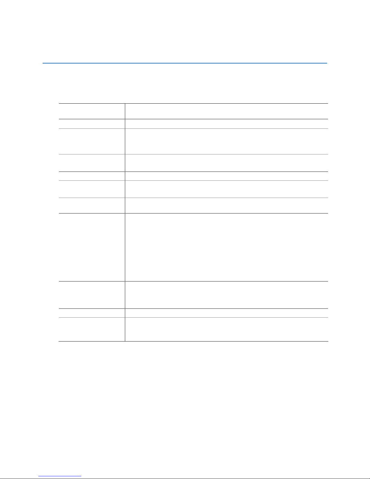
Table 1 summarizes the features of the Board.
Table 1. Featur
Form Factor
Processor
Main Memory • One 240-pin SDRAM Dual Inline Memory Module (DIMM) socket
Chipset • SiS662* Graphics and Memory Controller (Northbridge)
Graphics SiS Integrated Mirage* 1 Graphics Engine
Audio • ADI AD1888 Audio Codec
Expansion
Capabilities
Peripheral
Interfaces
BIOS
LAN Support • 10/100 Mb/s LAN Subsystem
Power
Management
e Summary
Mini-ITX (171.45 millimeters [6.75 inches] x 171.45 millimeters
[6.75 inches])
®
Celeron® processor
Intel
• 533/400 MHz single channel DDR2 SDRAM interface
• Supports up to 1 GB of system memory
• SiS964L* I/O Controller (Southbridge)
• Support for AC’97 two-channel audio
One PCI bus add-in card connector
• Six USB 2.0 ports
― Two ports routed to the back panel
― Four ports routed to two USB headers
• One IDE interface with ATA-100 support (two devices)
• One VGA connector
• One parallel port
• One serial port
• PS/2* keyboard and mouse ports
®
• Intel
• Support for SMBIOS
• Intel
• Support for Advanced Configuration and Power Interface (ACPI); no
• Wake on USB, PCI, PS/2, LAN, and front panel
BIOS
®
Rapid BIOS Boot
support for S3
9

Mini-ITX Motherboard 2807638 Product Guide
R
Supported Operating Systems
The Board supports the following operating systems:
• Microsoft Windows* XP Professional
• Microsoft Windows XP Home
• Microsoft Windows XP Starter Edition
10
Mini-ITX Motherboard Features
Mini-ITX Motherboard Components
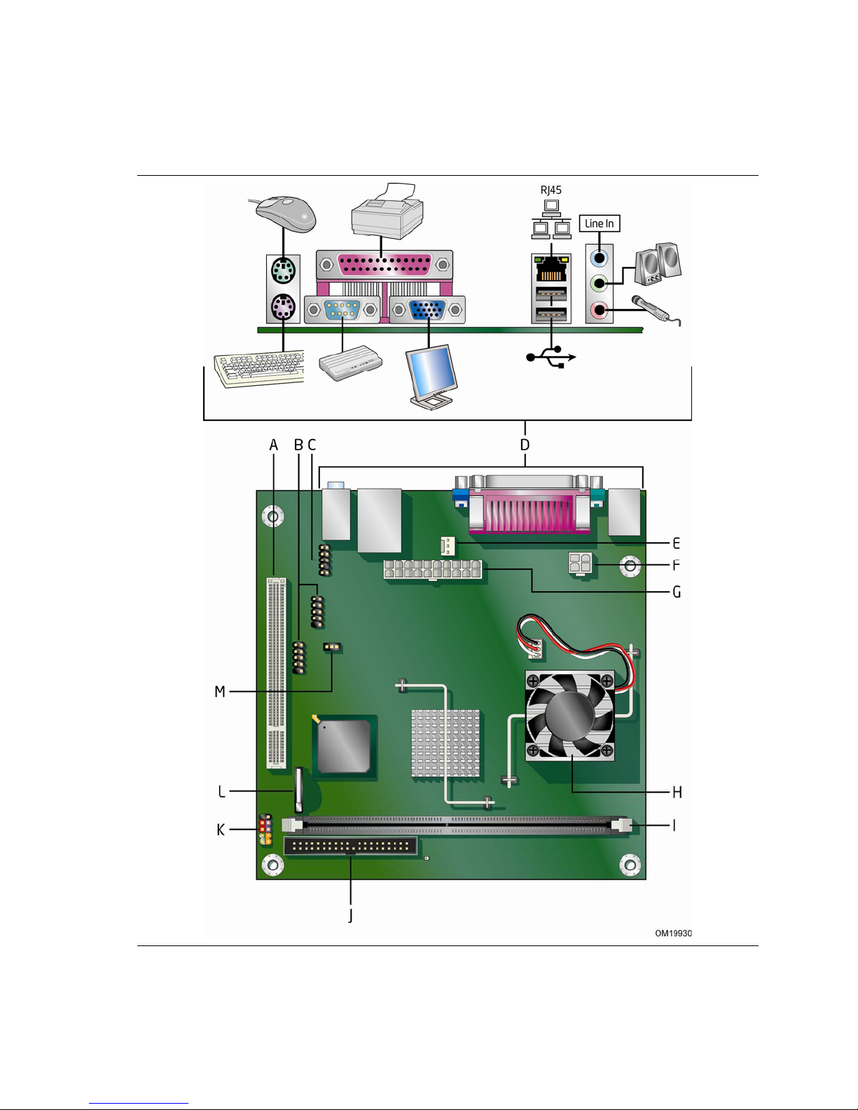
Figure 1 shows the location of the major components on Mini-ITX Motherboard 2807638.
Figure 1. Mini-ITX Motherboard 2807638 Components
11
Mini-ITX Motherboard 2807638 Product Guide
Table 2. Mini-ITX Motherboard 2807638 Components
Label Description
A PCI bus add-in card connector
B Hi-speed USB 2.0 headers
C Front panel audio header
D Back panel connectors
E Rear fan (3-pin) header
F 12 V processor core voltage connector (2 x 2)
G Main power connector (2 x 10)
H Processor
I DDR 2 DIMM connector
J IDE connector
K Front panel header
L Battery
M BIOS configuration jumper
12

Mini-ITX Motherboard Features
Processor
CAUTION
Failure to use an appropriate power supply and/or not connec ting the 12 V (2 x 2)
power connector to the Board may result in damage to the board, or the
system may not function properly.
The Mini-ITX Motherbaord 2807638 includes an Intel Celeron processor. The processor is
soldered to the Board and is not customer upgradeable.
Main Memory
NOTE
To be fully compliant with all applicable Intel® SDRAM memory specifications, the
board should be populated with DIMMs that support the Serial Presence Detect (SPD)
data structure. If your memory modules do not support SPD, you will see a
notification to this effect on the screen at power up. The BIOS will attempt to
configure the memory controller for normal operation.
The Board has one 240-pin Double Data Rate 2 (DDR2) SDRAM Dual Inline
Memory Module (DIMM) connector with gold-plated contacts. It supports:
• 533/400 MHz unbuffered, non-registered DDR2 DIMMs
• Serial Presence Detect (SPD) memory only
• Non-ECC memory
• Up to 1 GB of system memory utilizing 512 Mb or 1 Gb technology
13
 Loading...