

Global American LGA 775 Socket, 2807940 User Manual

x
2807940 User’s Manual
Micro ATX Motherboard with LGA 775 Socket
Version 1.
0
x

Copyrights
2807940 uATX Motherboard
This document is copyrighted and all rights are reserved. It does not allow any
authorization in copied
or machine readable form in whole or in part without prior written consent from
the manufacturer.
In general, the manufacturer will not be liable for any direct, indirect, special,
incidental or consequential damages arising from the use of inability to use the
product or documentation, even if advised of the possibility of such damages.
The manufacturer keeps
document without prior no
quality and reliability. The author assumes no responsibility for any errors or omissions,
which may appear in this document, nor does it make a commitment to update the
information contained herein.
Trademarks
Intel is a registered trademark of Intel Corporation.
, photocopied, translated or reproduced to any electronic
the rights in the subject to change the contents of this
tices in order to improve the function design, performance,
non
Award is a registered trademark of Award Software, Inc.
All other trademarks, products and or product's name mentioned herein are
mentioned for identification purposes only, and may be trademarks and/or
registered trademarks of their respective companies or owners.
x
2807940 uATX Motherboard
Manual Conventions
WARNING!
Warnings appear where overlooked details may cause damage to the equipment or result
in personal injury. Warnings should be taken seriously. Warnings are easy to recognize.
The word “warning” is written as “WARNING,” both capitalized and bold and is followed by
text. The text is the warning message. A warning message is shown below:
WARNING:
This is an example of a warning message. Failure to adhere to warning
messages may result in permanent damage to the 2807940 or
personal injury to the user. Please take warning messages seriously.
CAUTION!
Cautionary messages should also be heeded to help reduce the chance of losing data or
damaging the 2807940. Cautions are easy to recognize. The word “caution” is written as
“CAUTION,” both capitalized and bold and is followed. The italicized text is the cautionary
message. A caution message is shown below:
x
2807940 uATX Motherboard
CAUTION:
This is an example of a caution message. Failure to adhere to cautions
messages may result in permanent damage to the 2807940. Please
take caution messages seriously.
NOTE:
These messages inform the reader of essential but non-critical information. These
messages should be read carefully as any directions or instructions contained therein can
help avoid making mistakes. Notes are easy to recognize. The word “note” is written as
“NOTE,” both capitalized and bold and is followed by text. The text is the cautionary
message. A note message is shown below:
NOTE:
This is an example of a note message. Notes should always be read.
Notes contain critical information about the 2807940. Please take note
messages seriously.
x

2807940 uATX Motherboard
NOTE:
If any of the components listed in the checklist below are missing,
please do not proceed with the installation. Please contact the Global American,
Packing List
Inc. at (800) 833-8999
The items listed below should all be included in the 2807940 package.
1 x 2807940 single board computer
3 x SATA power cables
6 x SATA cables
1 x Dual RS-232 cable
1 x USB cable
1 x Mini jumper pack
1 x Utility CD
1 x IO shielding
1 x QIG (quick installation guide)
Images of the above items are shown in Chapter 3.
or link to Technical Support.
x

2807940 uATX Motherboard
Table of Contents
1 INTRODUCTION..................................................................................................... 1
1.1 OVERVIEW.................................................................................................................. 2
1.1.1 2807940 Features .............................................................................................. 3
1.2 2807940 OVERVIEW................................................................................................... 3
1.2.1 2807940 Overview Photo................................................................................... 3
1.2.2 2807940 Peripheral Connectors and Jumpers.................................................. 4
1.2.3 Technical Specifications..................................................................................... 6
2 DETAILED SPECIFICATIONS............................................................................. 8
2.1
DIMENSIONS............................................................................................................... 9
2.1.1 Board Dimensions.............................................................................................. 9
2.1.2 External Interface Panel Dimensions.............................................................. 10
2.2 DATA FLOW...............................................................................................................11
2.3 COMPATIBLE PROCESSORS ....................................................................................... 12
2.3.1 Supported Processors Overview...................................................................... 12
2.3.2 Supported Intel® Core™2 Quad (Yorkfield) Processors ................................ 12
2.3.3 Supported Intel® Core™2 Duo (Wolfdale) Processors................................... 13
2.3.4 Supported Intel® Core™2 Duo (Conroe) Processors..................................... 13
2.3.5 Supported Intel® Celeron® (Conroe) Processors........................................... 14
INTEL® Q35 NORTHBRIDGE CHIPSET....................................................................... 14
2.4
2.4.1 Intel® Q35 Northbridge Chipset ..................................................................... 14
2.4.2 Intel® Q35 Front Side Bus (FSB) Support...................................................... 14
2.4.3 Intel® Q35 Memory Controller....................................................................... 15
2.4.4 Intel® Q35 PCIe x16 Interface........................................................................ 16
2.4.5 Intel® Q35 Graphics and Display Features.................................................... 17
2.4.6 Intel® Q35 Analog Display Capability ........................................................... 17
2.4.7 Intel® Q35 Direct Media Interface (DMI) ...................................................... 18
2.5 INTEL
®
ICH9DO SOUTHBRIDGE CHIPSET ................................................................ 19
2.5.1 Intel® ICH9DO Overview................................................................................ 19
2.5.2 Intel® ICH9DO Features ................................................................................. 19
2.5.3 Intel® ICH9DO High Definition Audio Implementation................................. 20
P

2807940 uATX Motherboard
2.5.4 Intel® ICH9DO Ethernet Controller................................................................ 20
2.5.4.1 Intel® 82566DM Gigabit LAN Connect Device...................................... 21
2.5.5 Intel® ICH9DO Low Pin Count (LPC) Interface............................................. 22
2.5.6 Intel® ICH9DO PCI Interface.......................................................................... 23
2.5.7 Intel® ICH9DO PCIe x4 Bus............................................................................ 23
2.5.8 Intel® ICH9DO Real Time Clock ..................................................................... 23
2.5.9 Intel® ICH9DO SATA Controller ..................................................................... 24
2.5.10 Intel® ICH9DO Serial Peripheral Interface (SPI) BIOS............................... 25
2.5.11 Intel® ICH9DO USB Controller..................................................................... 25
2.5.11.1 Intel® ICH9DO USB Controller Overview............................................. 25
2.5.11.2 2807940 USB Implementation................................................................ 26
2.6
2807940 PCIE BUS COMPONENTS ........................................................................... 26
2.6.1 PCIe Bus Overview.......................................................................................... 26
2.6.2 PCIe x16 Slot ................................................................................................... 27
2.6.3 PCIe x4 Slot ..................................................................................................... 27
2.6.4 Intel® 82573L PCIe GbE Controller............................................................... 28
2.7 PCI BUS COMPONENTS ............................................................................................ 29
2.7.1 PCI Bus Overview............................................................................................ 29
2.7.2 PCI Slots .......................................................................................................... 29
2.8 LPC BUS COMPONENTS ........................................................................................... 30
2.8.1 LPC Bus Overview........................................................................................... 30
2.8.2 TPM Module .................................................................................................... 30
2.8.3 Super I/O chipset.............................................................................................. 31
2.8.3.1 Super I/O LPC Interface ........................................................................... 33
2.8.3.2 Super I/O 16C550 UARTs........................................................................ 33
2.8.3.3 Super I/O Enhanced Hardware Monitor................................................... 33
2.8.3.4 Super I/O Floppy Disk Drive (FDD) Controller....................................... 33
2.8.3.5 Super I/O Fan Speed Controller................................................................ 34
2.8.3.6 Super I/O Keyboard/Mouse Controller..................................................... 34
2.8.3.7 Super I/O GPIO Ports ............................................................................... 34
2.8.3.8 Super I/O Infrared..................................................................................... 34
2.8.3.9 Super I/O Parallel Port.............................................................................. 34
2.8.3.10 Super I/O Watchdog Timer ..................................................................... 35
2.8.4 Fintek F81216DG LPC Serial Port Chipset.................................................... 35
ETHERNET LAN CONTROLLERS............................................................................... 35
2.9
x

2807940 uATX Motherboard
2.10 ENVIRONMENTAL AND POWER SPECIFICATIONS ..................................................... 37
2.10.1 System Monitoring......................................................................................... 37
2.10.2 Operating Temperature and Temperature Control......................................... 37
2.10.3 Power Consumption....................................................................................... 38
3 UNPACKING .......................................................................................................... 39
3.1 ANTI-STATIC PRECAUTIONS...................................................................................... 40
3.2 UNPACKING.............................................................................................................. 40
3.2.1 Unpacking Precautions.................................................................................... 40
3.3 UNPACKING CHECKLIST ........................................................................................... 41
3.3.1 Package Contents............................................................................................. 41
3.4
OPTIONAL ITEMS...................................................................................................... 42
4 CONNECTOR PINOUTS...................................................................................... 43
4.1 PERIPHERAL INTERFACE CONNECTORS..................................................................... 44
4.1.1 2807940 Layout ............................................................................................... 44
4.1.2 Peripheral Interface Connectors ..................................................................... 45
4.1.3 External Interface Panel Connectors............................................................... 46
4.2 INTERNAL PERIPHERAL CONNECTORS ...................................................................... 47
4.2.1 ATX Power Connector ..................................................................................... 47
4.2.2 Audio CD In Connector................................................................................... 49
4.2.3 CPU Power Connector.................................................................................... 50
4.2.4 Digital Input/Output (DIO) Connector............................................................ 50
4.2.5 Fan Connector, CPU (12V, 4-pin).................................................................... 52
4.2.6 Fan Connector, System (+12V, 3-pin).............................................................. 53
4.2.7 Floppy Disk Connector (34-pin)...................................................................... 54
4.2.8 Front Audio Connector .................................................................................... 55
4.2.9 Front Panel Connector.................................................................................... 56
4.2.10 Infrared Interface Connector......................................................................... 57
4.2.11 PCIe Power Connector .................................................................................. 58
4.2.12 SATA Drive Connectors ................................................................................. 59
4.2.13 Serial Port Connector (COM2, COM 3 and COM4)..................................... 61
4.2.14 SPDIF Connector........................................................................................... 62
4.2.15 Trusted Platform Module (TPM) Connector.................................................. 63
4.2.16 USB Connectors (Internal)............................................................................ 64
x

2807940 uATX Motherboard
4.3 EXTERNAL PERIPHERAL INTERFACE CONNECTOR PANEL ......................................... 65
4.3.1 Audio Connectors............................................................................................. 65
4.3.2 Keyboard/Mouse Connector............................................................................ 66
4.3.3 LAN and Dual USB Combo Connectors.......................................................... 67
4.3.4 Parallel Port, Serial Port and VGA Combo Connector................................... 69
5 INSTALLATION.................................................................................................... 72
5.1 ANTI-STATIC PRECAUTIONS...................................................................................... 73
5.2 INSTALLATION CONSIDERATIONS.............................................................................. 74
5.2.1 Installation Notices.......................................................................................... 74
5.2.2 Installation Checklist....................................................................................... 75
5.3
UNPACKING.............................................................................................................. 76
5.3.1 Unpacking Precautions.................................................................................... 76
5.4 CPU, CPU COOLING KIT AND DIMM INSTALLATION.............................................. 76
5.4.1 Socket LGA775 CPU Installation.................................................................... 77
5.4.2 Socket LGA775 2107695 Cooling Kit Installation .......................................... 80
5.4.3 DIMM Installation........................................................................................... 82
5.4.3.1 DIMM Purchasing Guidelines.................................................................. 83
5.4.3.2 DIMM Installation Order.......................................................................... 83
5.4.3.3 DIMM Installation Guidelines.................................................................. 84
5.5 JUMPER SETTINGS .................................................................................................... 85
5.5.1 Clear CMOS Jumper........................................................................................ 86
5.5.2 COM Port Pin 9 Setting Jumpers .................................................................... 87
5.5.3 COM Port Pin 9 Voltage Setting Jumpers ....................................................... 89
CHASSIS INSTALLATION............................................................................................ 90
5.6
5.6.1 Airflow.............................................................................................................. 90
5.6.2 Motherboard Installation................................................................................. 91
5.7 INTERNAL PERIPHERAL DEVICE CONNECTIONS........................................................ 91
5.7.1 Peripheral Device Cables................................................................................ 91
5.7.2 Dual RS-232 Cable Connection....................................................................... 91
5.7.3 SATA Drive Connection ................................................................................... 92
5.7.4 USB Cable (Dual Port).................................................................................... 94
5.7.5 PCIe x16 Expansion Card Installation............................................................ 95
5.8 EXTERNAL PERIPHERAL INTERFACE CONNECTION ................................................... 96
5.8.1 Audio Connection............................................................................................. 96
x

2807940 uATX Motherboard
5.8.2 LAN Connection (Single Connector)............................................................... 97
5.8.3 Parallel Device Connection............................................................................. 98
5.8.4 PS/2 Keyboard and Mouse Connection........................................................... 99
5.8.5 Serial Device Connection .............................................................................. 100
5.8.6 USB Device Connection................................................................................. 101
5.8.7 VGA Monitor Connection .............................................................................. 102
6 INTEL
INTEL® AMT SETUP PROCEDURE ........................................................................... 105
6.1
6.2 INTEL
6.3 USING THE INTEL
A TERMINOLOGY..................................................................................................11
®
AMT CONFIGURATION..................................................................... 104
®
MANAGEMENT ENGINE BIOS EXTENSION................................................. 106
®
AMT WEB INTERFACE..............................................................111
4
B DIO INTERFACE...................................................................................................119
B.1 DIO INTERFACE INTRODUCTION .......................................................................... 120
B.2 DIO CONNECTOR PINOUTS.................................................................................... 120
B.3 ASSEMBLY LANGUAGE SAMPLES........................................................................... 121
B.3.1 Enable the DIO Input Function..................................................................... 121
B.3.2 Enable the DIO Output Function.................................................................. 121
C WATCHDOG TIMER............................................................................................ 122
D ADDRESS MAPPING......................................................................................... 125
D.1 ADDRESS MAP..................................................................................................... 126
1ST MB MEMORY ADDRESS MAP........................................................................ 126
D.2
D.3 IRQ MAPPING TABLE........................................................................................... 127
D.4 DMA CHANNEL ASSIGNMENTS............................................................................ 127
E COMPATIBILITY................................................................................................ 128
E.1 COMPATIBLE OPERATING SYSTEMS........................................................................ 129
E.2 COMPATIBLE PROCESSORS ..................................................................................... 129
E.3 COMPATIBLE MEMORY MODULES.......................................................................... 129
F INTEL
INTRODUCTION....................................................................................................... 132
F.1
®
MATRIX STORAGE MANAGER...................................................... 131
F.1.1 Precautions .................................................................................................... 132
F.2 FEATURES AND BENEFITS ....................................................................................... 133
x

2807940 uATX Motherboard
F.3 ACCESSING THE INTEL
®
MATRIX STORAGE MANAGER........................................... 133
F.4 RAID CONFIGURATION.......................................................................................... 134
F.4.1 Creating a RAID Volume................................................................................ 134
F.4.2 Deleting a RAID Volume................................................................................ 139
F.4.3 Resetting a Disk to Non-RAID....................................................................... 141
F.4.4 Exiting the Matrix Storage Manager ............................................................. 143
G HAZARDOUS MATERIALS DISCLOSURE................................................... 145
G.1 HAZARDOUS MATERIAL DISCLOSURE TABLE FOR IPB PRODUCTS CER TIFIED AS
ROHS COMPLIANT UNDER 2002/95/EC WITHOUT MERCURY ..................................... 146
H INDEX .................................................................................................................... 148
x

2807940 uATX Motherboard
List of Figures
Figure 1-1: 2807940 uATX Motherboard......................................................................................2
Figure 1-2: 2807940 Overview [Front View]................................................................................4
Figure 2-1: 2807940 Dimensions (mm)........................................................................................9
Figure 2-2: External Interface Panel Dimensions (mm)...........................................................10
Figure 2-3: Data Flow Block Diagram........................................................................................11
Figure 2-4: Front Side Bus (FSB)...............................................................................................15
Figure 2-5: DDR2 DIMM Sockets................................................................................................15
Figure 2-6: VGA Connector ........................................................................................................18
Figure 2-7: DMI Chip-to-Chip Connection.................................................................................18
Figure 2-8: Audio Connectors....................................................................................................20
Figure 2-9: Intel® 82566DM Gigabit LAN Connect Device ......................................................22
Figure 2-10: SATA Drive Connectors........................................................................................25
Figure 2-11: Onboard USB Implementation..............................................................................26
Figure 2-12: PCIe x16 Slot ..........................................................................................................27
Figure 2-13: PCIe x4 Slot ............................................................................................................28
Figure 2-14: Intel® 82573L PCIe GbE Controller......................................................................28
Figure 2-15: PCI Slots .................................................................................................................30
Figure 2-16: TPM Connector.......................................................................................................31
Figure 2-17: ITE IT8712F Super I/O............................................................................................32
Figure 2-18: LAN Connections...................................................................................................36
Figure 4-1: Connector and Jumper Locations..........................................................................44
Figure 4-2: ATX Power Connector Pinout Locations...............................................................48
Figure 4-3: Audio CD In Connector Pinouts (4-pin).................................................................49
Figure 4-4: CPU Power Connector Location.............................................................................50
Figure 4-5: DIO Connector Location..........................................................................................51
Figure 4-6: +12V Fan Connector Location................................................................................52
Figure 4-7: +12V Fan Connector Location................................................................................53
Page xiv

2807940 uATX Motherboard
Figure 4-8: 34-pin FDD Connector Location.............................................................................54
Figure 4-9: Front Audio Connector Location (10-pin) .............................................................55
Figure 4-10: Front Panel Connector Pinout Locations (14-pin)..............................................57
Figure 4-11: Infrared Connector Location.................................................................................58
Figure 4-12: PCIe Power Connector Location..........................................................................59
Figure 4-13: SATA Drive Connector Locations........................................................................60
Figure 4-14: Serial Connector Location....................................................................................61
Figure 4-15: SPDIF Connector Location ...................................................................................62
Figure 4-16: TPM Connector Location ......................................................................................63
Figure 4-17: USB Connector Locations ....................................................................................64
Figure 4-18: 2807940 External Peripheral Interface Connector..............................................65
Figure 4-19: Audio Connector....................................................................................................66
Figure 4-20: PS/2 Pinouts...........................................................................................................66
Figure 4-21: RJ-45 Ethernet Connector.....................................................................................68
Figure 4-22 Parallel Port Connector Pinout Locations............................................................69
Figure 4-23: COM1 Pinout Locations ........................................................................................70
Figure 4-24: VGA Connector ......................................................................................................71
Figure 5-1: Intel® LGA775 Socket..............................................................................................77
Figure 5-2: Remove the CPU Socket Protective Shield...........................................................78
Figure 5-3: Open the CPU Socket Load Plate...........................................................................79
Figure 5-4: Insert the Socket LGA775 CPU...............................................................................80
Figure 5-5: GAI 2107695 Cooling Kit .........................................................................................81
Figure 5-6: Securing the Heat sink to the PCB Board .............................................................82
Figure 5-7: DDR2 Channels........................................................................................................83
Figure 5-8: Installing a DIMM......................................................................................................85
Step 1: Figure 5-9: Clear CMOS Jumper............................................................................87
Figure 5-10: COM Port Pin 9 Setting Jumper Locations .........................................................88
Figure 5-11: COM Port Pin 9 Voltage Setting Jumper Locations ...........................................90
Figure 5-12: Dual RS-232 Cable Installation.............................................................................92
Figure 5-13: SATA Drive Cable Connection..............................................................................93
Figure 5-14: SATA Power Drive Connection.............................................................................93
Figure 5-15: Dual USB Cable Connection.................................................................................94
Page xv

2807940 uATX Motherboard
Figure 5-16: PCIe x16 Installation..............................................................................................95
Figure 5-17: Audio Connectors..................................................................................................97
Figure 5-18: LAN Connection.....................................................................................................98
Figure 5-19: Parallel Device Connector.....................................................................................99
Figure 5-20: PS/2 Keyboard/Mouse Connector..................................................................... 100
Figure 5-21: Serial Device Connector..................................................................................... 101
Figure 5-22: USB Device Connection..................................................................................... 102
Figure 5-23: VGA Connector ................................................................................................... 103
Figure 8-1: Intel® Active Management Technology Status Dialog...................................... 105
Figure 8-2: Intel® Current ME Password................................................................................ 107
Figure 8-3: Change Intel® ME Password ............................................................................... 107
Figure 8-4: Verify New Password............................................................................................ 108
Figure 8-5: Intel® AMT Configuration..................................................................................... 108
Figure 8-6: Provision Model .................................................................................................... 108
Figure 8-7: Intel® AMT 3.0 Mode............................................................................................. 109
Figure 8-8: Enterprise .............................................................................................................. 109
Figure 8-9: Enable Network Interface..................................................................................... 110
Figure 8-10: Exit........................................................................................................................ 111
Figure 8-11: Intel® AMT Web Address................................................................................... 112
Figure 8-12: Intel® AMT Web Login Dialog............................................................................ 112
Figure 8-13: Intel® AMT Web Interface................................................................................... 113
Page xvi

2807940 uATX Motherboard
List of Tables
Table 1-1: Technical Specifications.............................................................................................7
Table 2-1: Supported Intel® Core™2 Duo (Conroe) Processors............................................14
Table 2-2: Supported Intel® Celeron® Processors..................................................................14
Table 2-3: Power Consumption..................................................................................................38
Table 3-1: Package List Contents..............................................................................................42
Table 3-2: Package List Contents..............................................................................................42
Table 4-1: Peripheral Interface Connectors..............................................................................46
Table 4-2: Rear Panel Connectors.............................................................................................47
Table 4-3: ATX Power Connector Pinouts ................................................................................48
Table 4-4: Audio CD In Connector Pinouts...............................................................................49
Table 4-5: CPU Power Connector Pinouts................................................................................50
Table 4-6: DIO Connector Pinouts.............................................................................................51
Table 4-7: +12V Fan Connector Pinouts....................................................................................52
Table 4-8: +12V Fan Connector Pinouts....................................................................................53
Table 4-9: 34-pin FDD Connector Pinouts ................................................................................55
Table 4-10: Front Audio Connector Pinouts.............................................................................56
Table 4-11: Front Panel Connector Pinouts (14-pin) ...............................................................57
Table 4-12: Infrared Connector Pinouts....................................................................................58
Table 4-13: PCIe Power Connector Pinouts..............................................................................59
Table 4-14: SATA Drive Connector Pinouts..............................................................................60
Table 4-15: Serial Connector Pinouts........................................................................................61
Table 4-16: SPDIF Connector Pinouts.......................................................................................62
Table 4-17: TPM Connector Pinouts..........................................................................................63
Table 4-18: USB Port Connector Pinouts..................................................................................64
Table 4-19: PS/2 Connector Pinouts..........................................................................................67
Table 4-20: LAN Pinouts.............................................................................................................67
Table 4-21: RJ-45 Ethernet Connector LEDs............................................................................68
x

2807940 uATX Motherboard
Table 4-22: USB Port Pinouts.....................................................................................................68
Table 4-23: Parallel Port Connector Pinouts ............................................................................70
Table 4-24: RS-232 Serial Port (COM 1) Pinouts ......................................................................70
Table 4-25: VGA Connector Pinouts..........................................................................................71
Table 5-1: Jumpers......................................................................................................................86
Table 5-2: Clear CMOS Jumper Settings...................................................................................87
Table 5-3: COM Port Pin 9 Setting Jumper Settings................................................................88
Table 5-4: COM Port Pin 9 Voltage Setting Jumper Settings..................................................89
Table 5-5: GAI Provided Cables.................................................................................................91
x

2807940 uATX Motherboard
Chapter
1
1 Introduction
Page 1

1.1 Overview
2807940 uATX Motherboard
Figure 1-1: 2807940 uATX Motherboard
The 2807940 uATX form factor motherboard (Figure 1-1) is
Quad, Intel® Core™2 Duo or Intel® Celeron® CPU processor platform. Both 45nm core
(Wolfdale, Yorkfield) and 65nm core (Conroe) processors are supported. (For a full list of
supported processors please refer to Section 2.3)
Up to four 2.0 GB 667 MHz o
by the Intel® Q35 graphics memory controller hub (GMCH). The Intel® Q35 GMCH also
has a single PCI Express x16 (PCIe x16) expansion lane for a PCIe x16 graphics card.
The integrated Intel® ICH9DO I/O controller hub (ICH) supports six SATA II drives with
data transfer speeds of 3.0 Gbps with SATA RAID configuration support. Twelve USB 2.0
channels, one expansion PCIe x4 channel and two expansion PCI channels provide
flexible expansion options. Support for a (optional) trusted platform module (TPM)
provides additional system security during system boot-up.
r 800 MHz un-buffered DDR2 SDRAM DIMM are supported
an LGA775 Intel® Core™2
Page 2

2807940 uATX Motherboard
1.1.1 2807940 Features
Some of the 2807940 features are listed below.
Supports the following Intel® LGA775 processors:
o Intel® Core™2 Duo (45nm and 65nm)
o Intel® Core™2 Quad (45nm and 65nm)
o Intel® Celeron® (65nm)
Supports four 240-pin 2 GB 667 MHz or 800 MHz DDR2 DIMMs
Six SATA II drives with transfer rates of 3.0 Gbps supported
Twelve USB 2.0 devices supported (eight onboard and fou r on th e rear p an el)
Dual GbE Ethernet connectors
uATX form factor
RoHS compliant
Supports ATX power supplies
1.2 2807940 Overview
1.2.1 2807940 Overview Photo
The 2807940 has a wide variety of peripheral interface connectors. Figure 1-2 is a labeled
photo of the peripheral interface connectors on the 2807940.
Page 3

2807940 uATX Motherboard
Figure 1-2: 2807940 Overview [Front View]
1.2.2 2807940 Peripheral Connectors and Jumpers
The 2807940 has the following connectors on-board:
1 x ATX power connector
1 x Audio connector
1 x CD in connector
1 x Cooling fan connector , CPU
Page 4

2807940 uATX Motherboard
1 x Cooling fan connector, System
1 x CPU power connector
1 x Digital input/output connector
4 x DIMM sockets
1 x Floppy drive connector
1 x Front panel connector
1 x Infrared (IrDA) connector
2 x PCI slots
1 x PCIe x16 slots
1 x PCIe x4 slots
1 x PCIe power connector
6 x Serial ATA drive connectors
3 x Serial port connectors
1 x SPDIF connector
1 x SPI flash connector
1 x TPM connector
4 x USB connectors (support eight USB devices)
The 2807940 has the following external peripheral interface connectors on the board rear
panel.
3 x Audio jacks
2 x Keyboard/mouse connectors
1 x Parallel port
2 x RJ-45 Ethernet connectors
1 x Serial port
4 x USB 2.0 connectors
1 x VGA connector
The 2807940 has the following on-board jumpers:
Clear CMOS
COM port pin 9 setting
COM port pin 9 voltage setting
Page 5
2807940 uATX Motherboard
1.2.3 Technical Specifications
2807940 technical specifications are listed in Table 1-1. See Chapter 2 for details.
Specification 2807940
Form Factor
System CPU
Front Side Bus (FSB)
System Chipset
Memory
Super I/O
Display
uATX
LGA775 Intel® Core™2 Quad
LGA775 Intel® Core™2 Duo
LGA775 Intel® Celeron®
800 MHz, 1066 MHz or 1333 MHz
Northbridge: Intel® Q35 Express Chipset
Southbridge: Intel® ICH9DO
Four 240-pin DDR2 DIMM sockets support 2.0 GB 667 MHz or
800 MHz DDR2 DIMMs
ITE IT8712F Rev. I
Analog VGA display through external DB-15 connector
AMI BIOS label
BIOS
Audio
LAN
COM
USB2.0
Page 6
SPI EEPROM
4.0 MB
RealT ek AL C883 codec.
One Intel® 82566DM (PHY) and Intel® ICH9DO (MAC)
One PCIe x1 Intel® 82573L (MAC and PHY)
Four RS-232 serial ports
Three by onboard pin-headers
One by external connector
Twelve USB 2.0 devices supported:
Eight by onboard pin-headers
2807940 uATX Motherboard
Four by external connectors
SATA
SATA RAID Levels
Keyboard/mouse
Digital I/O
Watchdog Timer
Infrared
Power Supply
TPM
Fan Connector
Six 3.0 Gb/s SATA II drives supported
RAID 0, RAID 1, RAID 5 and RAID 10
By external PS/2 connector through the ITE IT8712F super I/O
One 8-bit digital input/output connector; 4-bit input/4-bit output
through the ITE IT8712F super I/O
Software programmable 1-255 sec. through the ITE IT8712F
super I/O
One IrDA connector through the ITE IT8712F super I/O.
ATX power supply
Supports TPM v1.2 with 20-pin onboard pin-header
Three pin system fan pin-header
Four pin CPU fan pin-header
Buzzer
Power Consumption
Temperature
Humidity (operating)
Dimensions (LxW)
Weight (GW)
Table 1-1: Technical Specifications
Yes
3.3V@2.41A, 5V@5.71A, +12V@3.69A (3Dmark® 2001) and
5VSB@0.13A (3.0 GHz E6850 Intel® Core™2 Duo CPU with
four 2.0 GB, 800 MHz DDR2 DIMM running 3Dmark® 2001)
0ºC – 60ºC (32ºF - 140ºF)
5%~95% non-condensing
244 mm x 244 mm
1.1 kg
Page 7

2807940 uATX Motherboard
Chapter
2
2 Detailed Specifications
Page 8

2807940 uATX Motherboard
2.1 Dimensions
2.1.1 Board Dimensions
The dimensions of the board are listed below:
Length: 243.84mm
Width: 243.84mm
Figure 2-1: 2807940 Dimensions (mm)
Page 9

2.1.2 External Interface Panel Dimensions
External peripheral interface connector panel dimensions are shown in Figure 2-2.
Figure 2-2: External Interface Panel Dimensions (mm)
2807940 uATX Motherboard
Page 10
2807940 uATX Motherboard
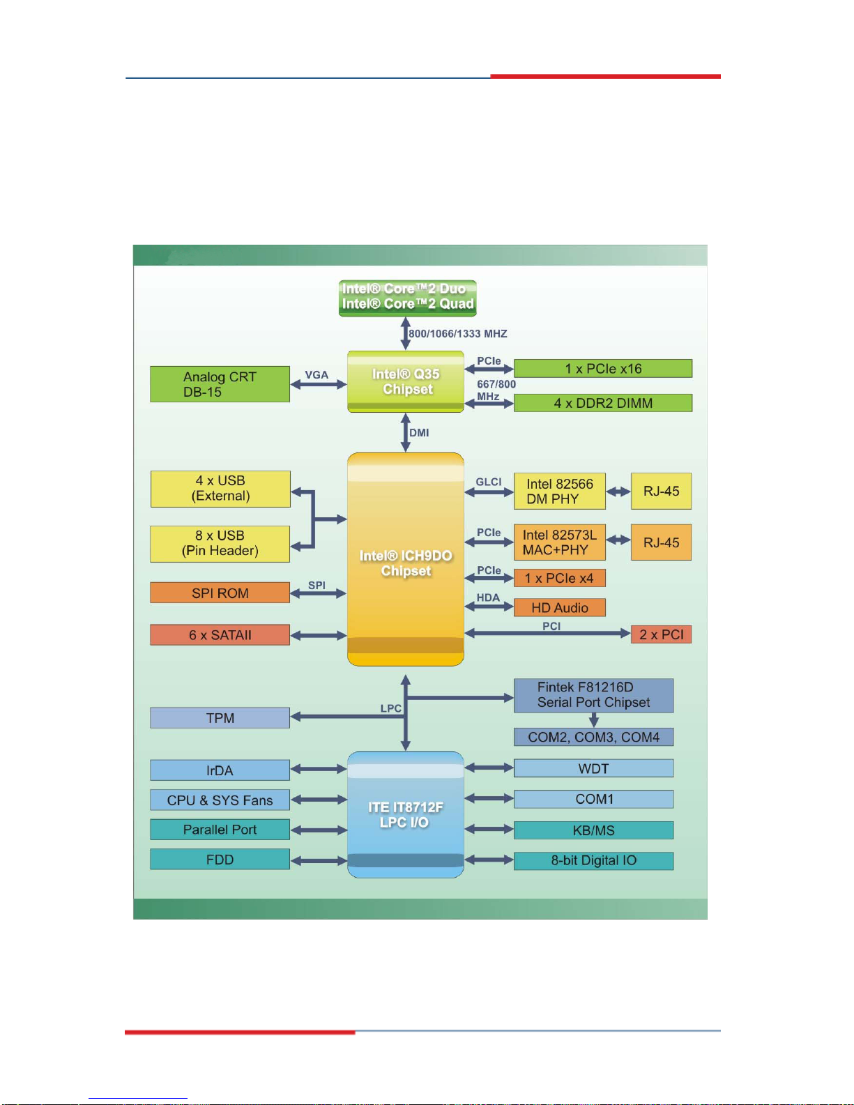
2.2 Data Flow
Figure 2-3 shows the data flow between the two on-board chipsets and other components
installed on the motherboard and described in the following sections of this chapter.
Figure 2-3: Data Flow Block Diagram
Page 11
2807940 uATX Motherboard
2.3 Compatible Processors
2.3.1 Supported Processors Overview
The 2807940 supports the following Intel® LGA775 processors
Intel® Core™2 Quad (Yorkfield)
Intel® Core™2 Duo (Wolfdale)
Intel® Core™2 Duo (Conroe)
Intel® Celeron® (Conroe)
2.3.2 Supported Intel® Core™2 Quad (Yorkfield) Processors
The Yorkfield core Intel® Core™2 Quad CPU is a 45nm LGA775 processor.
NOTE:
As of the date of writing this manual (December, 2007), Intel® has not
released Intel® Core™2 Quad (Yorkfield) processor numbers that are
supported by the Intel® Northbridge. As soon as processor numbers
are released, the manual will be updated.
For further details about supported Intel® Core™2 Quad (Yorkfield)
processors, please contact Intel® directly.
Page 12
2807940 uATX Motherboard
2.3.3 Supported Intel® Core™2 Duo (Wolfdale) Processors
The Wolfdale core Intel® Core™2 Duo CPU is a 45nm LGA775 processor.
NOTE:
As of the date of writing this manual (December, 2007), Intel® has not
released Wolfdale core Intel® Core™2 Duo processor numbers that
are supported by the Intel® Q35 Northbridge. As soon as processor
numbers are released, the manual will be updated.
For further details about supported Intel® Core™2 Duo (Wolfdale)
processors, please contact Intel® directly.
2.3.4 Supported Intel® Core™2 Duo (Conroe) Processors
Table 2-1 lists the Conroe core Intel® Core™2 Duo processors supported on the
2807940. All the processors in Table 2-1 are 65nm LGA775 processors with the following
features:
Enhanced Halt State (C1E)
Enhance Intel® Speedstep® Technology
Execute Disable Bit
Intel® 64
Intel® Thermal Monitor 2
Intel® Virtualization Technology
Intel® Dual Core Technology
Page 13

2807940 uATX Motherboard
Processor # CPU Speed FSB Speed Cache Size
E6850 3.0 GHz 1333 MHz 4 MB
Table 2-1: Supported Intel® Core™2 Duo (Conroe) Processors
2.3.5 Supported Intel® Celeron® (Conroe) Processors
Table 2-1 lists the Conroe core Intel® Celeron® processors supported on the 2807940. All
the processors in Table 2-1 are 65nm LGA775 processors with the following features:
Execute Disable Bit
Intel® 64
Processor # CPU Speed FSB Speed Cache Size
440 2.0 GHz 800 MHz 512kB
Table 2-2: Supported Intel® Celeron® Processors
2.4 Intel® Q35 Northbridge Chipset
2.4.1 Intel® Q35 Northbridge Chipset
The Intel® Q35 Northbridge chipset is an advanced Graphics and Memory Controller Hub
(GMCH) that supports a range of Intel® processors including 45nm Wolfdale dual core
and Yorkfield quad core and 65nm Conroe core processors. The Intel® Q35 Northbridge
supports 1333 MHz, 1066 MHz, or 800 MHz FSB and up to 8.0 GB of 667 MHz or 800
MHz DDR2 SDRAM. The Intel® Q35 Northbridge is interfaced to an Intel® ICH9DO
Southbridge chipset through a Direct Media Interface (DMI) communications link.
2.4.2 Intel® Q35 Front Side Bus (FSB) Support
The Intel® Q35 Northbridge supports processors with the following FSB speeds:
800 MHz
1066 MHz
Page 14
 Loading...