

Global American 3308220 User Manual

3308220 User’s Manual
Version V1.1
3.5" Embedded Controller

Copyrights
This document is copyrighted and all rights are reserved. It does not allow any non
authorization in copied, photocopied, translated or reproduced to any electronic or
machine readable form in whole or in part without prior written consent from the
manufacturer.
In general, the manufacturer will not be liable for any direct, indirect, special, incidental
or consequential damages arising from the use of inability to use the product or
documentation, even if advised of the possibility of such damages. The manufacturer
keeps the rights in the subject to change the contents of this document without prior
notices in order to improve the function design, performance, quality and reliability. The
author assumes no responsibility for any errors or omissions, which may appear in this
document, nor does it make a commitment to update the information contained herein.
Trademarks
Intel is a reg
istered trademark of Intel Corporation.
Award is a registered trademark of Award Software, Inc.
All other trademarks, products and or product's name mentioned herein are mentioned
for identification purposes only, and may be trademarks and/or registered trademarks of
their respective companies or owners.

Table of Contents
Chapter 1 General Description ..................................1
1.1 Major Features....................................................................... 2
1.2 Specifications ........................................................................ 3
1.3 Board Dimensions................................................................. 4
Chapter 2 Unpacking .................................................. 5
2.1 Opening the Delivery Package............................................. 5
2.2 Inspection............................................................................... 5
Chapter 3 Hardware Installation ..............................7
3.1 Before Installation ................................................................. 7
3.2 Board Layout ......................................................................... 8
3.3 Jumper List ............................................................................ 9
3.4 Connector List ....................................................................... 9
3.5 Configuring the CPU ............................................................. 9
3.6 System Memory ................................................................... 10
3.7 VGA Controller .................................................................... 10
3.8 IDE Drive Connector ........................................................... 12
3.9 Serial ATA Connector ......................................................... 12
3.10 Serial Port Connectors ....................................................... 13
3.11 Ethernet Connector ............................................................. 14
3.12 USB Port............................................................................... 15
3.13 CMOS Data Clear................................................................. 15
3.14 Power and Fan Connectors................................................ 15
3.15 Keyboard/Mouse Connectors ............................................ 16
3.16 System Front Panel Control ............................................... 16
3.17 Watchdog Timer .................................................................. 17
3.18 TV-Out Function .................................................................. 19
3.19 PC/104 Plus Connector....................................................... 20
3.20 Audio Connectors ............................................................... 21
3.21 CompactFlash Connector................................................ 22
3.22 8-bit I/O Function................................................................. 23

Chapter 4 AMI BIOS Setup..................................... 29
4.1 Starting Setup...................................................................... 29
4.2 Using Setup ......................................................................... 30
4.3 Main Menu............................................................................ 31
4.4 Advanced Settings .............................................................. 32
4.5 Advanced PCI/PnP Settings............................................... 37
4.6 Boot Settings ....................................................................... 38
4.7 Security Settings ................................................................. 39
4.8 Advanced Chipset Settings................................................ 40
4.9 Exit Options ......................................................................... 43

Safety Instructions
Integrated circuits on computer boards are sensitive to static electricity. To
avoid damaging chips from electrostatic discharge, observe the following
precautions:
Do not remove boards or integrated circuits from their anti-static packaging
until you are ready to install them.
Before handling a board or integrated circuit, touch an unpainted portion of
the system unit chassis for a few seconds. This helps to discharge any static
electricity on your body.
Wear a wrist-grounding strap, available from most electronic component
stores, when handling boards and components. Fasten the ALLIGATOR clip
of the strap to the end of the shielded wire lead from a grounded object.
Please wear and connect the strap before handle th
e 3308220 to ensure
harmlessly discharge any static electricity through the strap.
Please use an anti-static pad when putting down any components or parts or
tools outside the computer. You may also use an anti-static bag instead of
the pad. Please inquire from your local supplier for additional assistance in
finding the necessary anti-static gadgets.
NOTE:
DO NOT TOUCH THE BOARD OR ANY OTHER SENSITIVE
COMPONENTS WITHOUT ALL NECESSARY ANTI-STATIC
PROTECTIONS.
1
Chapter 1
General Description
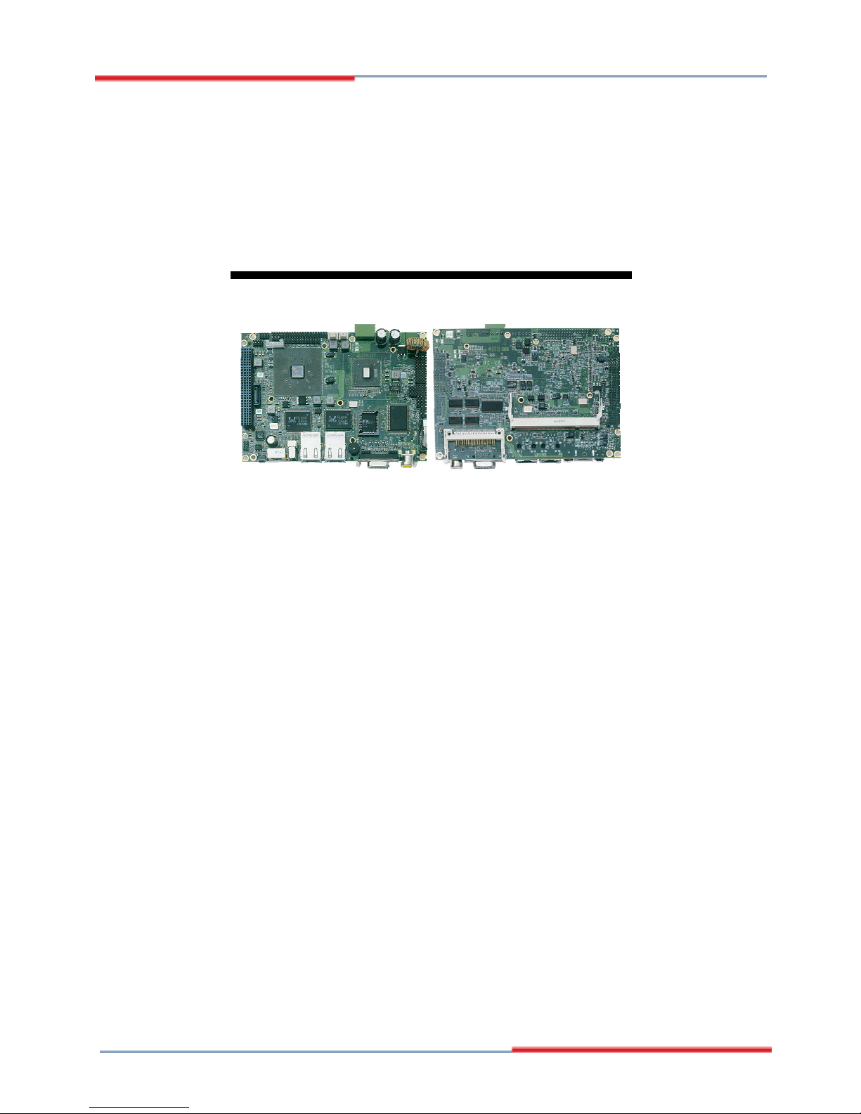
The 3308220 is a VIA CX700 chipset-based board designed. The
3308220 is an ideal all-in-one embedded engine board. Additional
features include an enhanced I/O with CF, CRT/LVDS, TV-Out, dual
LAN, audio, SATA, 4 COM, USB2.0, and PC/104 Plus interfaces.
Its onboard ATA/33/66/100 to IDE drive interface architecture allows
the 3308220 to support data transfers of 33 or 66MB/sec. to one IDE
drive connection. Designed with the VIA CX700, the board supports
VIA C7 or ULV VIA V4 Eden 600MHz~2.0GHz CPU.
The VIA CX700 with 32/64/128MB shared main memory supports
CRT/Panel displays up to 2048 x 1536. It also supports 24-bit single
channel/48-bit dual channel LVDS interface supporting up to 1600 x
1200.
System memory is also sufficient with the one SO-DDRII socket that
can support up to 1G.
Additional onboard connectors include an advanced USB2.0 port
providing faster data transmission. And two RJ-45 connectors for
10/100 Based Ethernet uses. To ensure the reliability in an unmanned
or standalone system
, the watchdog timer (WDT) onboard 3308220 is
designed with software that does not need the arithmetical functions of
a real-time clock chip. If any program causes unexpected halts to the
system, the onboard WDT will automatically reset the CPU or generate
an interrupt to resolve such condition.
2
1.1 Major Features
The 3308220 comes with the following features:
VIA C7 or ULV VIA V4 Eden processor 600MHz~2.0GHz
One SO-DDRII socket with a max. capacity of 1GB
VIA CX700 system chipset
Winbond W83697UG super I/O chipset
VIA CX700 graphics controller
24-bit/48-bit LVDS Panel display interface
Dual RealTek RTL8100C Ethernet controller
VIA VT1708A HD audio controller

3
VIA CX700 Serial ATA controller
Fast PCI ATA/33/66/100 IDE controller
CF, 8-bit I/O, 4 COM, 5 USB2.0, PC/104 Plus
+10~+30V wide range single DC power in
TV-Out, Hardware Monitor function
1.2 Specifications
CPU:
ULV VIA V4 Eden processor 600MHz/800MHz/1.0GHz
VIA C7 processor 1.0~2.0GHz
Front Side Bus:
Supports 400MHz FSB
Memory:
One SO-DDRII socket supports up to 1GB
Chipset:
VIA CX700
I/O Chipset:
Winbond W83697UG
CompactFlash: One, Type I/II IDE interface adapter
8-bit I/O: 8-bit input/output port (parallel)
VGA: VIA CX700 with 32/64/128MB shared main memory supports CRT
display up to 2048 x 1536
LVDS Panel: Supports 24-bit single channel/48-bit dual channel LVDS
interface up to 1600 x 1200
TV-Out:
Provides PAL or NTSC TV systems
Ethernet:
Dual RealTek RTL8100C 10/100 Based LAN
Audio: VIA VT1708A HD audio controller
Serial ATA: VIA CX700 controller with 1 port
IDE: One 2.0-pitch 44-pin IDE connector
Serial Port: 16C550 UART-compatible RS-232/422/485 x 1 and RS-232
x 3 serial ports with 16-byte FIFO
PC/104 Plus: PC/104 Bus connector for PCI Bus
USB: 5 USB2.0 ports, internal x 4 and external x 1
Keyboard/Mouse: PS/2 6-pin Mini DIN
BIOS: AMI PnP Flash BIOS
Watchdog Timer: Software programmable time-out intervals from
1~255 sec.
CMOS: Battery backup
Power In: +10~+30V wide range single DC power in
Temperature: 0~+60°C (operating)
Hardware Monitor: Winbond W83L784R
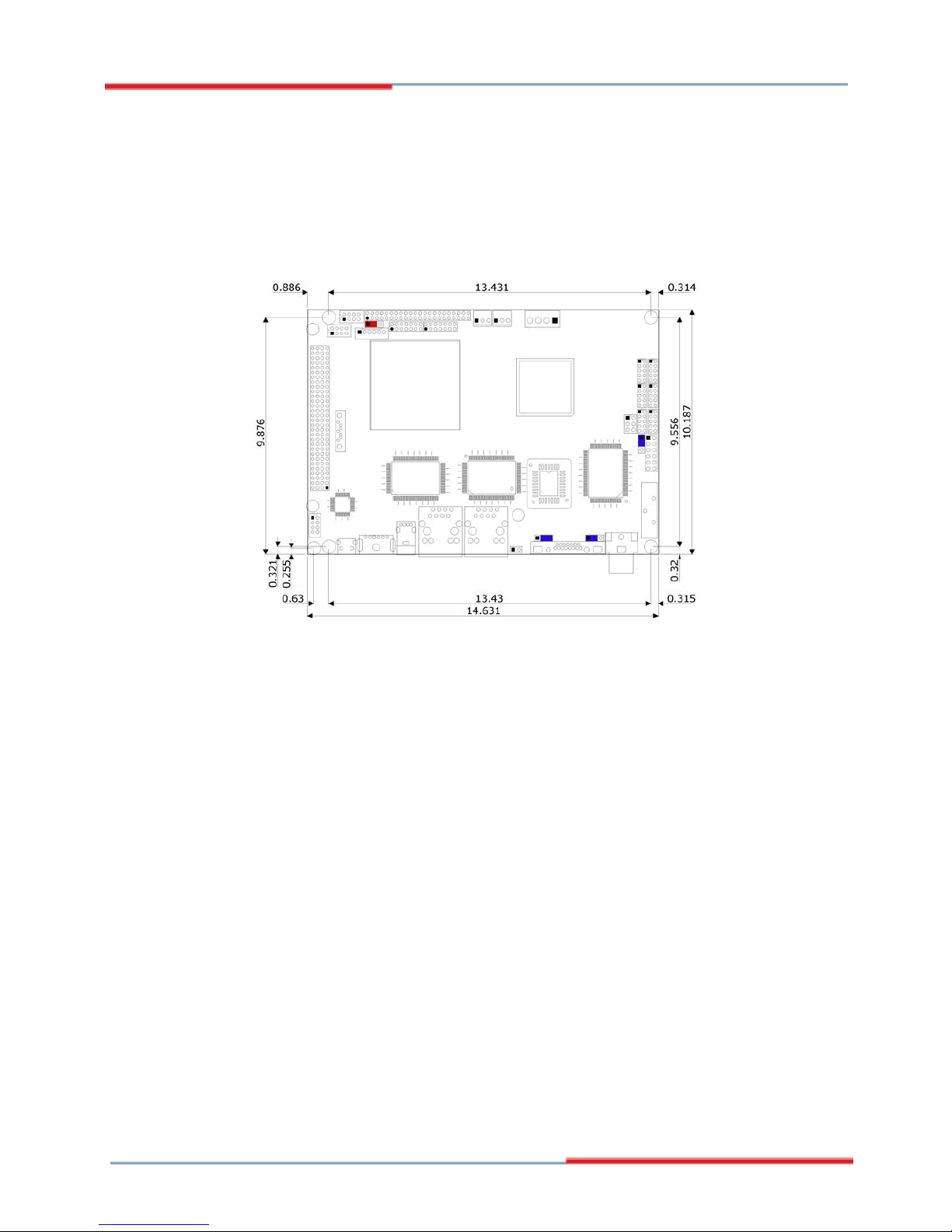
Board Size: 14.5(L) x 10.2(W) cm
4
1.3 Board Dimensions

5
Chapter 2
Unpacking
2.1 Opening the Delivery Package
The 3308220 is packed in an anti-static bag. The board has
c
omponents that are easily damaged by static electricity. Do not
remove the anti-static wrapping until proper precautions have been
taken. Safety Instructions in front of this manual describe anti-static
precautions and procedures.
2.2 Inspection
After unpacking the board, place it on a raised surface and carefully
inspect the board for any damage that might have occurred during
shipment. Ground the board and exercise
extreme care to prevent
damage to the board from static electricity.
Integrated circuits will sometimes come out of their sockets during
shipment. Examine all integrated circuits, particularly the BIOS,
processor, memory modules, ROM-Di sk, and keyboard controller chip
to ensure that they are rmly seated. The
3308220 delivery package
contains the following items:
3308220 Board x 1
Utility CD Disk x 1
Cables Package x 1
Jumper Bag x 1
User’s Manual
6
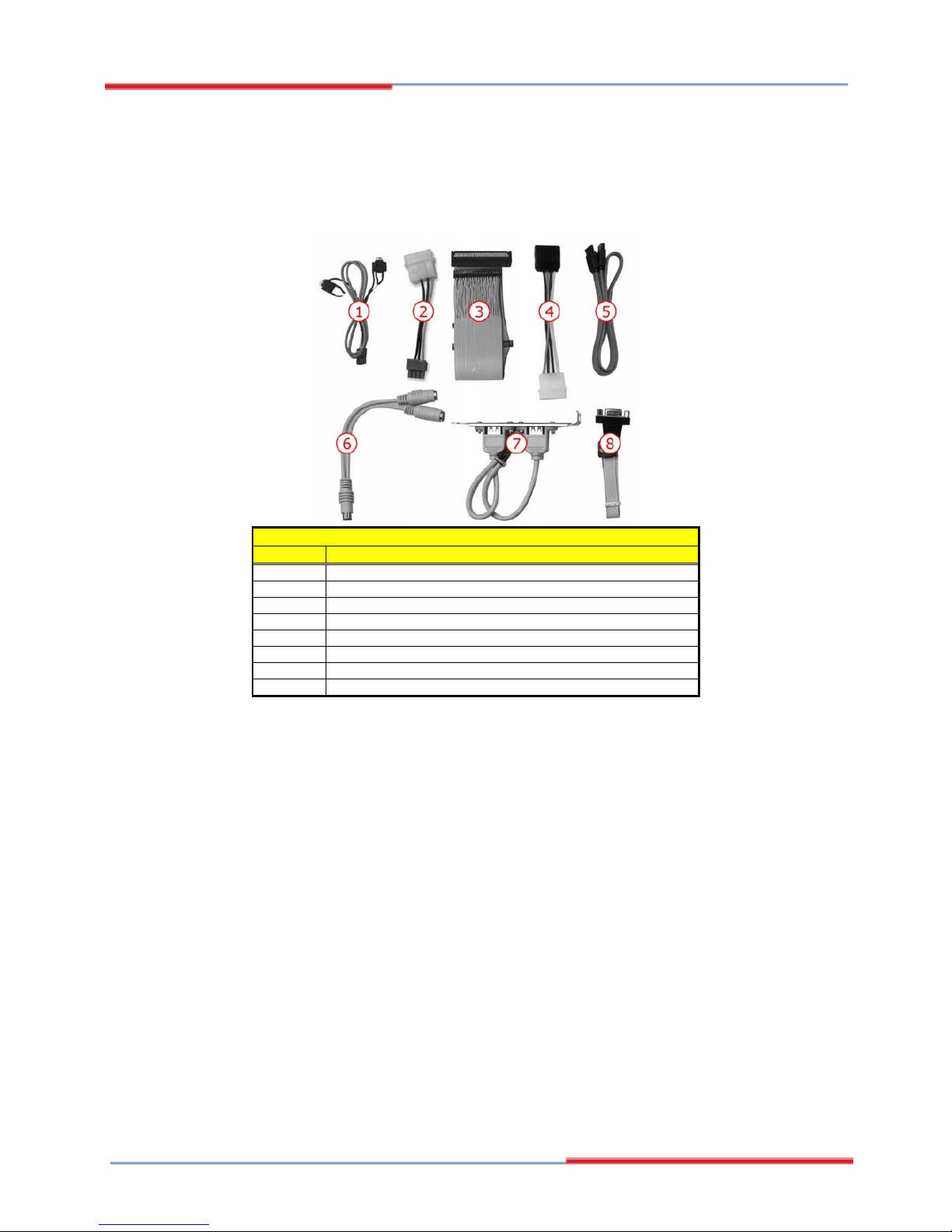
Cables Package
NO. Description
1
Audio cable x 1
2 4-pin power cable x 1
3 IDE flat cable x 1
4 SATA power cable x 1 (optional)
5 SATA cable x 1 (optional)
6 Keyboard/Mouse transfer cable x 1
7 2 USB cable with bracket x 1 (optional)
8 Serial port flat cable x 1
It is recommended that you keep all the parts of the delivery package
intact and store them in a safe/dry place for any unforeseen event
requiring the return shipment of the product. In case you discover any
missing and/or damaged items from the list of items, please contact
your dealer immediately.

7
Chapter 3
Hardware Installation
This chapter provides the information on how to install the hardware
using th
e 3308220. This chapter also contains information related to
jumper settings of switch, and watchdog timer selection etc.
3.1 Before Installation
After confirming your package contents, you are now ready to install
your hardware. The following are important reminders and steps to
take before you begin with your installation process.
1. Make sure that all jumper settings match their default settings
and CMOS setup correctly. Refer to the sections on this chapter
for the default settings of each jumper. (JP5 short 1-2)
2. Go through the connections of all external devices and make
sure that they are installed properly and configured correctly
within the CMOS setup. Refer to the sections on this chapter
for the detailed information on the connectors.
3. Keep the manual and diskette in good condition for future
reference and use.
8
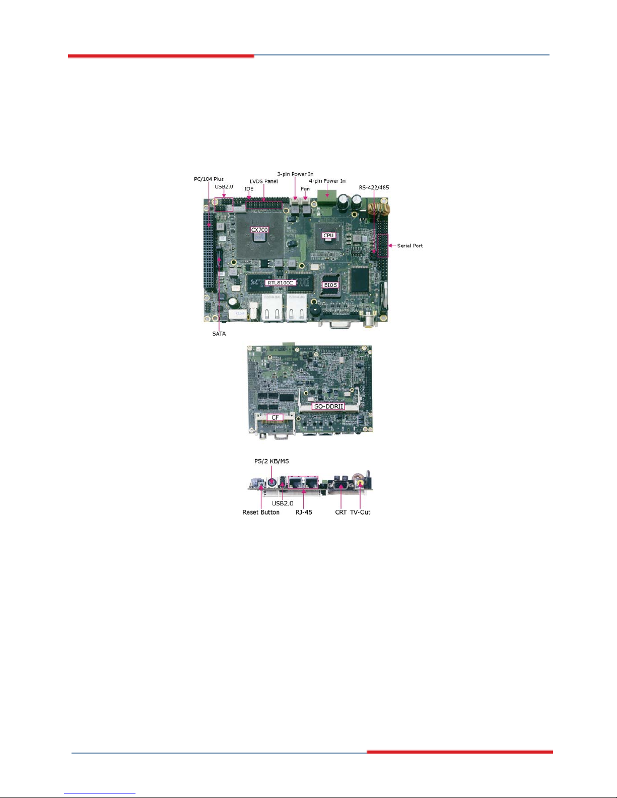
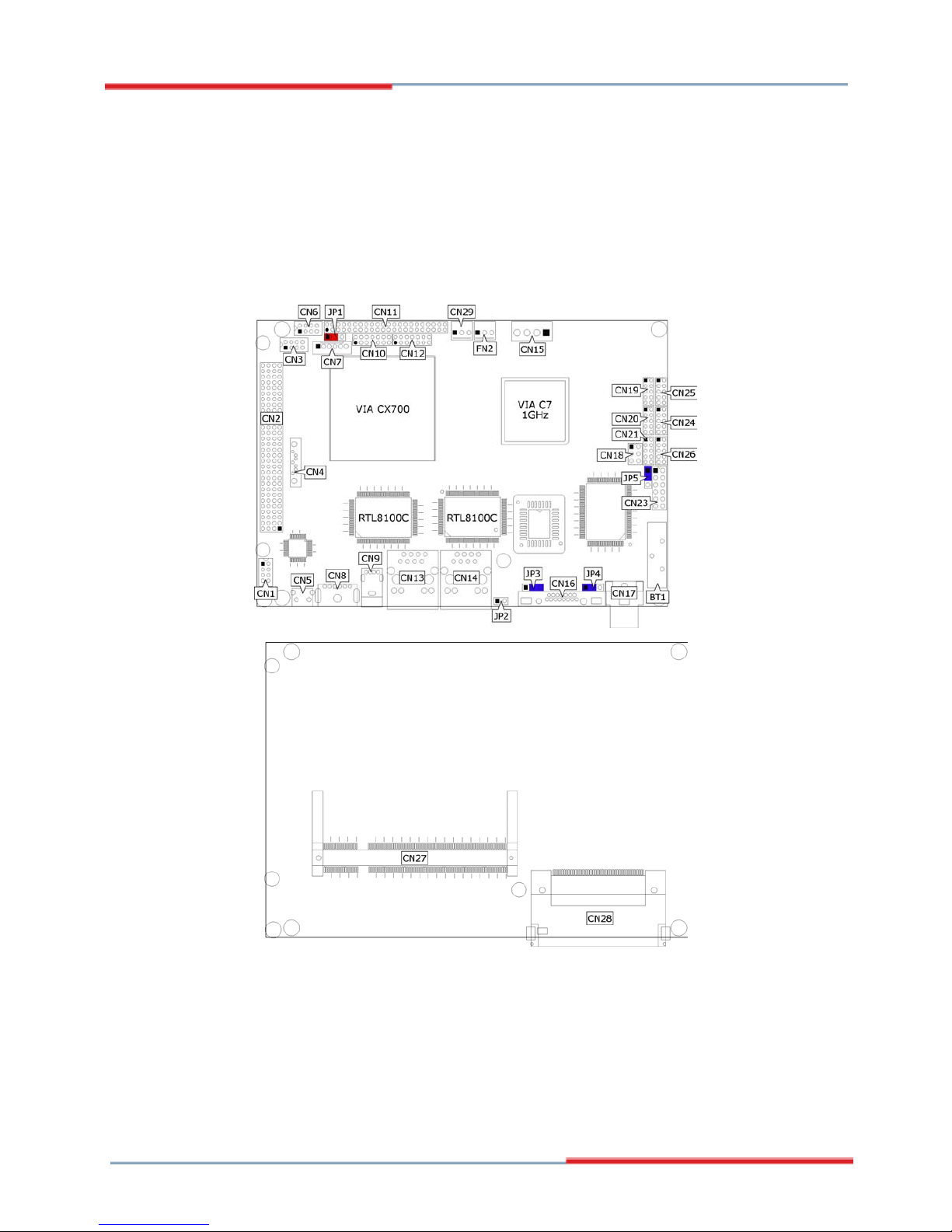
3.2 Board Layout
9
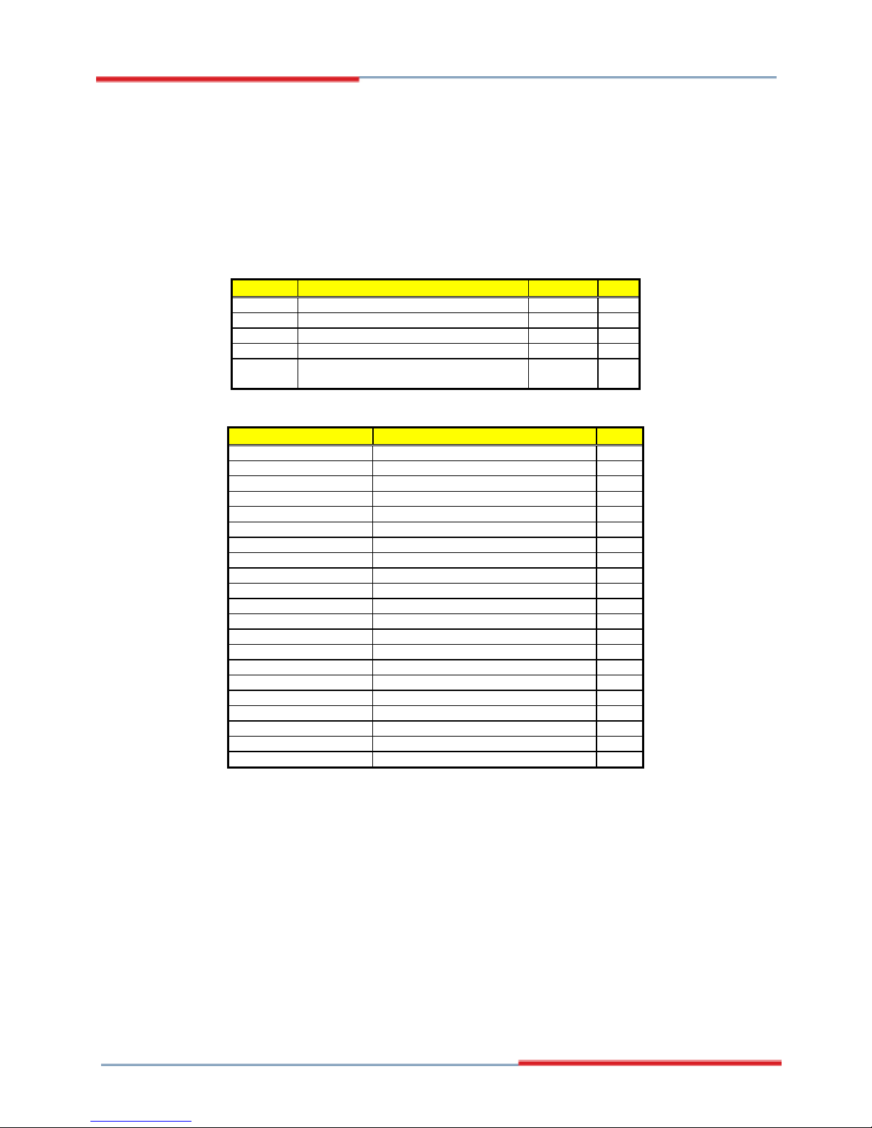
3.3 Jumper List
Jumper Default Setting Setting Page
JP1 Panel Voltage Select: +3.3V Short 1-2 10
JP3 CF Use Master/Slave Select: Slave Short 2-3 22
JP4 Display Out Function Select: CRT Short 1-2 19
JP5
Clear CMOS: Normal Operation Short 1-2 15
CN25
COM2 Use RS-232 or RS-422/485 Select:
RS-232
Open 13
3.4 Connector List
Connector Definition Page
CN1 MIC In/Line Out Connector 21
CN2 PC/104 Plus Connector 20
CN3/CN6/CN9 USB2.0 Port 15
CN4
Serial ATA Connector 12
CN5 Reset Button 16
CN7 Inverter Power In Connector 10
CN8 PS/2 6-pin Mini DIN 16
CN10/CN12 LVDS Panel Connector 10
CN11
IDE Connector 12
CN13/CN14 RJ-45 Connector 14
CN15 4-pin Power In Connector 15
CN16 15-pin CRT Connector 10
CN17 TV-Out Connector 19
CN18 RS-422/485 Connector 13
CN19 8-bit Input/Output 23
CN24/CN20/CN21/CN26 COM 1~COM 4 Connector (5x2 header) 13
CN23 System Front Panel Control 16
CN27 SO-DDRII Socket 10
CN28 CompactFlash Connector 22
CN29 External Power In Connector 15
FN2 Fan Power In Connector 15
3.5 Configuring the CPU
The 3308220 embedded with ULV VIA V4 Eden 600MHz/800MHz/
1GHz or VIA C7 1.0/1.5/2.0GHz CPU. User don’t need to adjust the
frequently and check speed of CPU.

10
3.6 System Memory
The 3308220 provides one SO-DDRII socket at locations CN27. The
maximum capacity of the onboard memory is 1GB.
3.7 VGA Controller
The 3308220 provides two connection methods of a VGA device.
CN
25 offers
an internal 10-pin CRT connector and CN6/CN9 are the
LVDS interface connectors onboard reserved for flat panel installation.
CN16: 15-pin CRT Connector
PIN Description PIN Description
1 Red 2 Green
3 Blue 4 N/C
5 GND 6 GND
7 GND 8 GND
9 N/C 10 GND
11 N/C 12 SDA
13
HSYNC
14
VSYNC
15 SDC
1
5
15
10
6
11
CN10/CN12: LVDS Interface Connector
PIN Description PIN Description
1 V
LCD
2 V
LCD
3 GND 4 GND
5 A0-/B0- 6 A0+/B0+
7 A1-/B1- 8 A1+/B1+
9 A2-/B2- 10 A2+/B2+
11 CLK1-/CLK2- 12 CLK1+/CLK2+
13 A3-/B3- 14 A3+/B3+
12
13 14
NOTE:
LVDS cable should be produced very carefully. A0- & A0+ have to
be fabricated in twister pair (A1- & A1+, A2- & A2+ and so on)
otherwise the signal won’t be stable. Please set the proper voltage
of your panel using JP1 before proceeding on installing it.
 Loading...