

Global American 3308170 User Manual

User’s Manual
Single B oard Computer 3308170
Version 1.0 ,
Month 2008

Copyrights
This manual is copyrighted and all rights are reserved. It does not allow any
non authorization in copied, photocopied, translated or reproduced to any
electronic or machine readable form in whole or in part without prior written
consent from the manufacturer.
In general, the manufacturer will not be liable for any direct, indirect, special,
incidental or consequential damages arising from the use of inability to use
the product or documentation, even if advised of the possibility of such
damages. The manufacturer keeps the rights in the subject to change the
contents of this manual without prior notices in order to improve the function
design, performance, quality and reliability. The author assumes no
responsibility for any errors or omissions, which may appear in this manual,
nor does it make a commitment to update the information contained herein.
Trademarks
Intel is a registered trademark of Intel Corporation.
Award is a registered trademark of Award Software, Inc.
All other trademarks, products and or product's name mentioned herein are
mentioned for identification purposes only, and may be trademarks and/or
registered trademarks of their respective companies or owne rs.

Index
Chapter 1 Introduction ...........................................................1
Chapter 2 Installation ............................................................ 9
Chapter 3 BIOS ...................................................................... 25
Chapter 4 Appendix ............................................................... 56
Introduction
1Chapter 1
Introduction
Chapter 1 - Introduction
Index
Chapter 1 Introduction ...........................................................1
Chapter 2 Installation ............................................................ 9
Chapter 3 BIOS ...................................................................... 25
Chapter 4 Appendix ............................................................... 56
Introduction
Packing List
1
3308170
3.5
” Embedded Board
1 x Driver CD
1 x Quick Installation Guide
1 x CPU Cooler
90 x 66 x 27.8mm (L x W x H)
1 x ATX Power cable
ATX main power connector (2x10 pins) to EmCORE-i9651
power connector (2x5 pins)
If any of the above items is damaged or missing, contact your vendor
immediately.

Index
Chapter 1 Introduction ...........................................................1
Chapter 2 Installation ............................................................ 9
Chapter 3 BIOS ...................................................................... 25
Chapter 4 Appendix ............................................................... 56
Introduction
1.9 Specications
Form Factor 3.5” Embedded Board
CPU
mPGA 478 Socket for Intel® Core™ 2 Duo Processor, up
to FSB 800MHz
Chipset Intel
®
GME965 + Intel® ICH8M
System Memory
1 x 200-pin SO-DIMM socket Up to 2GB DDR II
533/667MHz SDRAM
VGA/ LCD Controller
Mobile Intel® Graphics Media Accelerator (GMA) X3100
graphics core w/ CRT/ LVDS 24-bit dual Channel
Ethernet
2 x Realtek 8111B PCIe 10/100/1000 Base-T Fast
Ethernet LAN
I/O Chips
Winbond W83627HG
BIOS AMI PnP Flash BIOS
Audio Realtek ALC888 HD Codec, MIC-in/Line-in/Line-out
Serial ATA
2 x Serial ATA 300MB/s HDD transfer rate
IDE Interface 1 x IDE (Ultra ATA 33), support 2 IDE devices
Serial Port 2 x COM port (COM1: RS-232; COM2: RS-232/422/485)
Parallel Port/ Floppy
1 x LPT Port (SPP/EPP/ECP mode selectable)
1 x Floppy connector share with LPT port
IrDA 1 x IrDA connector
KBMS Standard PS/2 Keyboard and Mouse
Universal Serial Bus 6 x USB 2.0 compliant
DIO 8-bit programmable Digital I/O
Expansion Interface
1 x CF II Socket (Share with IDE)
1 x Mini PCI Socket
Hardware Monitor Chip Integrated in W83627HG
Operation Temp. -20oC ~ +70oC (-4oF ~ 158oF)
Watchdog Timer
255-level Reset
Dimension (L x W) 146 x 102 mm ( 5.7 ” x 4.0 ” )
Index
Chapter 1 Introduction ...........................................................1
Chapter 2 Installation ............................................................ 9
Chapter 3 BIOS ...................................................................... 25
Chapter 4 Appendix ............................................................... 56
Introduction
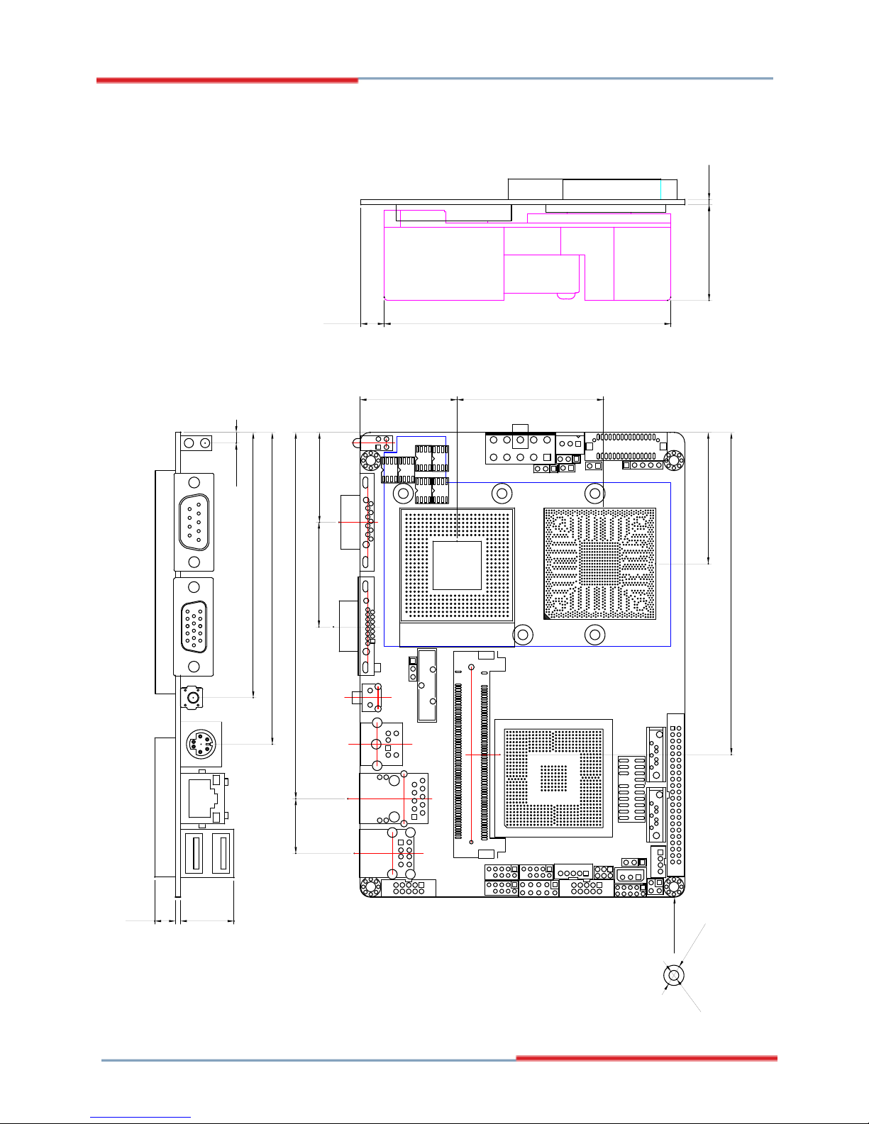
1.10 Board Dimensions
Unit:mm
Layout Top View
28.24
32.87
115.11 17.15
101.25
46.99
108.14
30.11.6
16.86.5
3.38 95.2
101.96
8.84133.93
30.48 45.98
41.27
1.2
67.2
3.35
83.36
97.97
?3.1
?6.35
7.32 90
1
2
1
1
1
Index
Chapter 1 Introduction ...........................................................1
Chapter 2 Installation ............................................................ 9
Chapter 3 BIOS ...................................................................... 25
Chapter 4 Appendix ............................................................... 56
Introduction
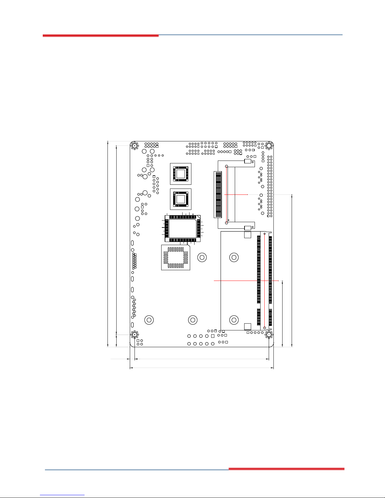
Unit:mm
Layout Bottom View
46.99
108.14
3.38 95.2
101.96
8.84133.93
146
NO COMPONENT
Index
Chapter 1 Introduction ...........................................................1
Chapter 2 Installation ............................................................ 9
Chapter 3 BIOS ...................................................................... 25
Chapter 4 Appendix ............................................................... 56
Introduction
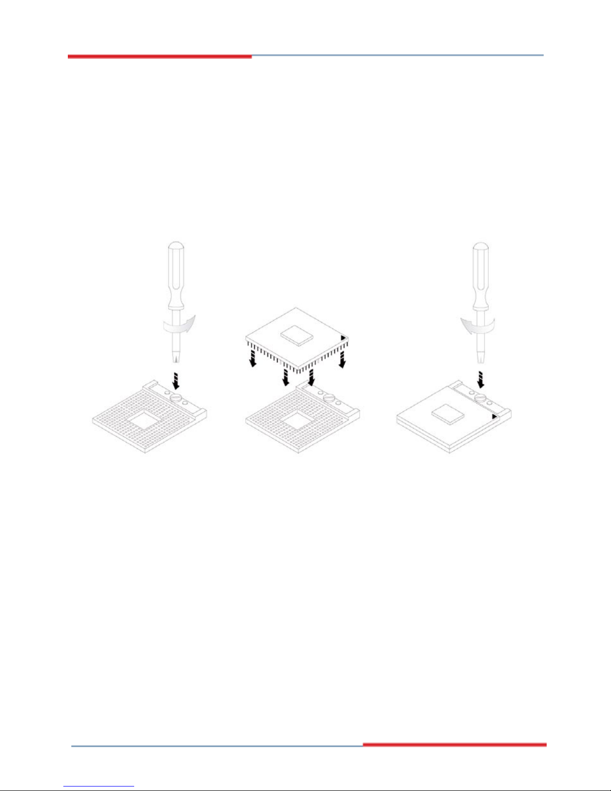
1.11 Installing the CPU
The processor socket comes with a screw to secure the CPU. As showing in
the picture as bellow, loose the screw rst before inserting the CPU.
Place the CPU into the socket by making sure the notch on the corner of the
CPU corresponding with the notch on the inside of the socket. Once the CPU
has slide into the socket, lock the screw.
Make sure that heat sink of the CPU top surface is in complete contact to
avoid the CPU overheating problem.
If not, it would cause your system or CPU to be hanged, unstable, damaged.
Index
Chapter 1 Introduction ...........................................................1
Chapter 2 Installation ............................................................ 9
Chapter 3 BIOS ...................................................................... 25
Chapter 4 Appendix ............................................................... 56
Introduction
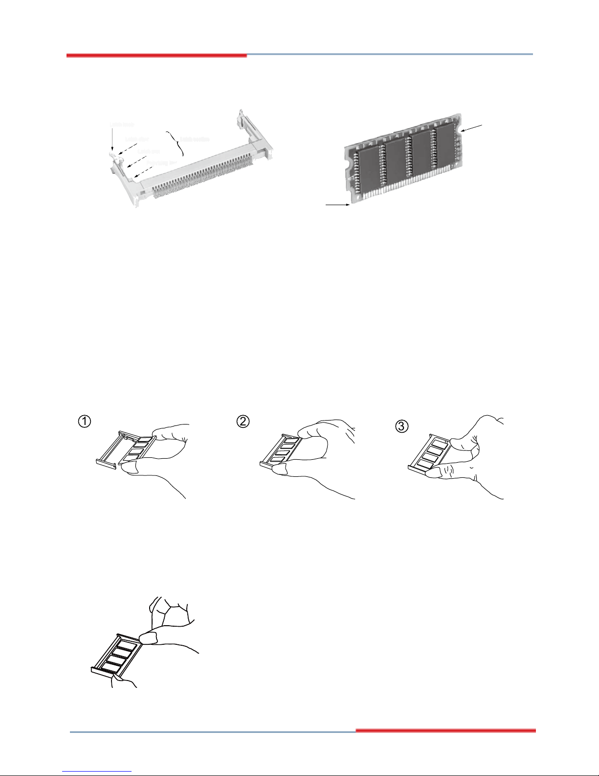
1.12 Installing the Memory
To install the Memory module, locate the Memory SO-DIMM slot on the
board and perform as below:
Adjust the socket polarizing key and the board key to the same direction.
Insert the board obliquely. Moreover, lay the board in parallel to the
opening at angle of 20
o
to 30o, and softly insert the board so as to hit the
socket bottom. Stopping insertion halfway will result in improper insertion.
Applying the board side notch in parallel to the socket bottom so that the
board position cannot be displaced, press the board side notch up, and
x it to the latch portion at both socket edges. Press the board side notch,
and release the notch with a snap “click” tone, if the printed board exceeds
the latch claw head.
1.
2.
3.
Side notch
Key
Latch knob
Latch claw
Latch section
Latch arm
Polarizing key
1
2
3
Procedures for board extraction
Apply the thumb nail to the latch knob at both socket edges. Forcibly widen
the latch knobs to right and left ways, and release the latch. Then draw the
board out along an angle where the board is raised.
Index
Chapter 1 Introduction ...........................................................1
Chapter 2 Installation ............................................................ 9
Chapter 3 BIOS ...................................................................... 25
Chapter 4 Appendix ............................................................... 56
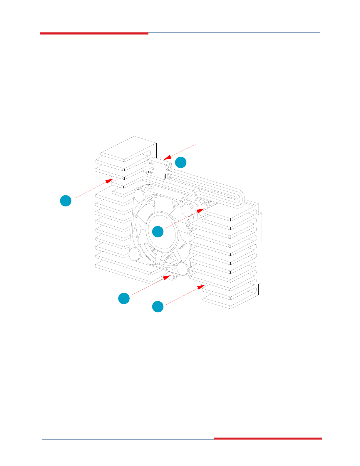
Introduction
Put the heatsink on 3308170
, and screw it on in the direction of
the board. Insert four screws (No. 1) downward into the holes and turn
them tightly.
Verify the direction is correct (No. 2) and plug the FAN connector into
CPUF1 connector.
1.
2.
1.13 Heatsink Installation
FAN Connector
1
1
1
1
2
Index
Chapter 1 Introduction ...........................................................1
Chapter 2 Installation ............................................................ 9
Chapter 3 BIOS ...................................................................... 25
Chapter 4 Appendix ............................................................... 56
Introduction
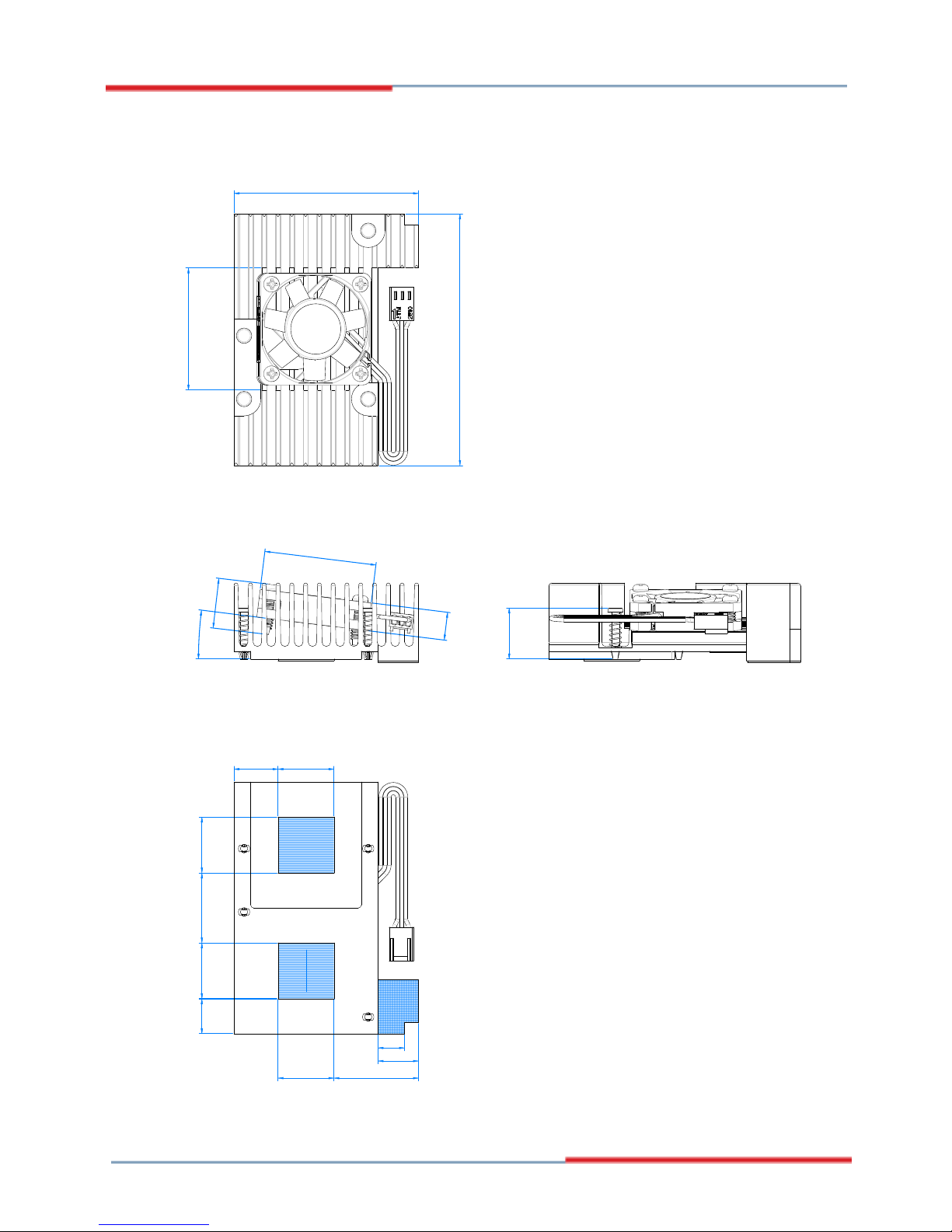
1.14 Heatsink Dimensions
90
66
20
20
20
20
40
14.5
43.7
10
15.75
12.5
7°
17.9
18.3
25
30.25
9.5
 Loading...