

Global American 3308050A, 3308050B User Manual

Single Board Computer
Version 1.0, September
User’s Manual
3308050
2006

Copyrights
This manual is copyrighted and all rights are reserved. It does not allow any non authorization in
copied, photocopied, translated or reproduced to any electronic or machine readable form in
whole or in part without prior written consent from the manufacturer.
In general, the manufacturer will not be liable for any direct, indirect, special, incidental or
consequential damages arising from the use of inability to use the product or documentation, even
if advised of the possibility of such damages. The manufacturer keeps the rights in the subject to
change the contents of this manual without prior notices in order to improve the function design,
performance, quality and reliability. The author assumes no responsibility for any errors or
omissions, which may appear in this manual, nor does it make a commitment to update the
information contained herein.
Trademarks
Intel is a registered trademark of Intel Corporation.
Award is a registered trademark of Award Software, Inc.
All other trademarks, products and or product's name mentioned herein are mentioned for
identification purposes only, and may be trademarks and/or registered trademarks of their
respective companies or owners.

3308050 Motherboard
Table of Contents
1 INTRODUCTION.................................................................................................... 13
1.1 3308050 O
1.1.1 3308050 Models................................................................................................ 14
1.1.2 Optional 3907720 Daughterboard................................................................... 14
1.1.3 3308050 Applications....................................................................................... 14
1.1.4 3308050 Benefits.............................................................................................. 14
1.1.5 3308050 Features..............................................................................................15
1.2 3308050 O
1.2.1 3308050 Connectors ........................................................................................ 17
1.2.2 3907720 Daughterboard Connectors.............................................................. 18
1.3 T
ECHNICAL SPECIFICATIONS .................................................................................... 20
1.3.1 3308050 Specifications .................................................................................... 20
1.3.2 Optional 3907720 Daughterboard Technical Specifications ........................... 21
2 DETAILED SPECIFICATIONS........................................................................... 23
2.1 OVERVIEW ............................................................................................................... 24
2.2 BOARD DIMENSIONS................................................................................................ 24
2.3 CPU SUPPORT.......................................................................................................... 25
VERVIEW .................................................................................................14
VERVIEW ................................................................................................ 16
2.4 SYSTEM CHIPSET ..................................................................................................... 26
2.5 DATA FLOW.............................................................................................................. 27
RAPHICS SUPPORT ................................................................................................. 28
2.6 G
2.7 OPTIONAL 3907720 LVDS DISPLAY SUPPORT...........................................................29
2.8 MEMORY SUPPORT................................................................................................... 29
2.9 PCI BUS INTERFACE SUPPORT ................................................................................. 29
2.10 ETHERNET CONTROLLER ....................................................................................... 30
2.10.1 Introduction.................................................................................................... 30
2.10.2 Realtek RTL8110S Features........................................................................... 30
2.11 DRIVE INTERFACES ................................................................................................ 31
2.11.1 SATA Drives.................................................................................................... 31
2.11.2 IDE HDD Interfaces....................................................................................... 31
2.11.3 Compact Flash Support.................................................................................. 31
2.12 S
ERIAL PORTS ........................................................................................................ 31
3

2.13 REAL TIME CLOCK................................................................................................. 32
2.14 SYSTEM MONITORING............................................................................................ 32
2.15 INFRARED DATA ASSOCIATION (IRDA) INTERFACE................................................ 32
2.16 USB INTERFACES................................................................................................... 32
2.17 BIOS ..................................................................................................................... 32
2.18 OPERATING TEMPERA TURE AND TEMPERATURE CONTROL..................................... 33
2.19 AUDIO CODEC........................................................................................................ 33
2.20 POWER CONSUMPTION........................................................................................... 34
2.21 PACKAGED CONTENTS AND OPTIONAL ACCESSORY ITEMS..................................... 35
2.21.1 Package Contents........................................................................................... 35
2.21.2 Optional Accessory Items............................................................................... 35
3 CONNECTORS AND JUMPERS ......................................................................... 37
3.1 PERIPHERAL INTERFACE CONNECTORS .................................................................... 38
3.1.1 3308050 Layout................................................................................................ 38
3.1.2 Peripheral Interface Connectors ..................................................................... 39
3.1.3 External Interface Panel Connectors............................................................... 41
3.1.4 On-board Jumpers........................................................................................... 42
3.2 INTERNAL PERIPHERAL CONNECTORS...................................................................... 43
3.2.1 +5VSB PS_ON................................................................................................. 43
3.2.2 –12V Power Supply.......................................................................................... 44
3.2.3 AT Power Connector........................................................................................ 44
3.2.4 Audio Connector .............................................................................................. 45
3.2.5 Compact Flash Connector............................................................................... 46
3.2.6 Fan Connector................................................................................................. 48
3.2.7 Front Panel Connector.................................................................................... 50
3.2.8 GPIO Connector.............................................................................................. 51
3.2.9 IDE Connector (Primary)................................................................................ 52
3.2.10 IDE Connector (Secondary) .......................................................................... 54
3.2.11 Inverter Power Connector.............................................................................. 56
3.2.12 IR Interface Connector .................................................................................. 57
3.2.13 LVDS Connector............................................................................................ 58
3.2.14 Keyboard/Mouse Connector.......................................................................... 59
3.2.15 LCD LVDS Converter Module Connector 1.................................................. 60
3.2.16 LCD LVDS Converter Module Connector 2.................................................. 62
3.2.17 Parallel Port Connector ................................................................................ 63
4
0-4
Global American Inc.

3308050 Motherboard
3.2.18 PC/104 Slot....................................................................................................
64
3.2.19 PCI-104 Slot................................................................................................... 68
3.2.20 PCI Slot.......................................................................................................... 71
3.2.21 Power Switch Connector................................................................................ 75
3.2.22 Reset Button Connector ................................................................................. 76
3.2.23 RS-232 Serial Port Connectors...................................................................... 77
3.2.24 RS-232/422/485 Serial Port Connector......................................................... 78
3.2.25 SATA Drive Connectors ................................................................................. 79
3.2.26 TTL Connector............................................................................................... 80
3.2.27 Internal USB Connectors............................................................................... 81
3.2.28 VGA Connector (Internal) ............................................................................. 82
3.3 E
XTERNAL INTERFACE CONNECTORS....................................................................... 83
3.3.1 LAN Connectors............................................................................................... 84
4 INST ALLA TION AND CONFIGURA TION ....................................................... 87
4.1 ANTI-STATIC PRECAUTIONS...................................................................................... 88
4.2 INSTALLATION CONSIDERATIONS ............................................................................. 88
4.2.1 Installation Notices.......................................................................................... 88
4.3 UNPACKING.............................................................................................................. 89
4.3.1 Unpacking Precautions.................................................................................... 89
4.3.2 Checklist........................................................................................................... 90
4.4 3308050 MOTHERBOARD INSTALLATION................................................................. 90
4.4.1 Preinstalled Components................................................................................. 91
4.4.2 Components to Install...................................................................................... 91
4.4.3 DIMM Module Installation.............................................................................. 91
4.4.3.1 Purchasing the Memory Module............................................................... 91
4.4.3.2 DIMM Module Installation....................................................................... 92
4.4.4 Optional 3907720 Daughterboard Installation............................................... 93
4.4.4.1 18-bit LVDS Connectivity ........................................................................ 93
4.4.4.2 24-bit LVDS Connectivity ........................................................................ 94
4.4.5 Peripheral Device Connection......................................................................... 95
4.4.5.1 IDE Disk Drive Connector (IDE1) ........................................................... 96
4.4.5.2 Compact Flash Connector......................................................................... 97
4.4.5.3 Parallel Port Connector (LPT1)................................................................ 97
4.4.5.4 Audio Interface.......................................................................................... 97
4.4.5.5 COM Port Connectors [COM1, COM2, COM3 and COM4]................... 98
5

4.5 JUMPER SETTINGS.....................................................................................................98
4.5.1 Clear CMOS Jumper........................................................................................ 99
4.5.2 CF Card Setup ............................................................................................... 100
4.5.3 LCD Voltage Setup Jumper............................................................................ 101
4.5.4 RS-232/485 Setup........................................................................................... 102
4.5.5 RS-422/485 Jumper........................................................................................ 103
4.5.6 COM2 Voltage Setup Jumper......................................................................... 104
4.6 CHASSIS INSTALLATION ......................................................................................... 106
4.7 REAR ETHERNET CONNECTORS.............................................................................. 106
6
Global American Inc.

3308050 Motherboard
A W
ATCHDOG TIMER ......................................................................................... 107
B ADDRESS MAPPING.......................................................................................... 111
B.1 IO A
DDRESS MAP ................................................................................................... 112
B.2 1ST MB MEMORY ADDRESS MAP ........................................................................... 112
B.3 IRQ MAPPING TABLE...............................................................................................113
.B4 DMA CHANNEL ASSIGNMENTS................................................................................113
C EXTERNAL AC’97 AUDIO CODEC .................................................................115
NTRODUCTION ....................................................................................................... 116
C.1 I
C.1.1 Accessing the AC’97 CODEC......................................................................... 112
C.1.2 Driver Installation............................................................................................116
C.2 SOUND EFFECT CONFIGURATION............................................................................. 117
C.2.1 Accessing the Sound Effects Manager............................................................ 117
C.2.2 Sound Effect Manager Configuration Options ............................................... 119
7

List of Figures
Figure 1-1: 3308050 Overview ...................................................................................16
Figure 1-2: 3308050 Solder Side Overview ..............................................................17
Figure 1-3: 3907720 Daughterboard Overview (Front Side)...................................19
Figure 2-1: 3308050 Dimension (mm).......................................................................24
Figure 2-2: 3308050 External Interface Connector Dimensions (mm)...................25
Figure 2-3: Data Flow Block Diagram........................................................................27
Figure 3-1: Connector and Jumper Locations.........................................................38
Figure 3-2: Connector and Jumper Locations (Solder Side)..................................39
Figure 3-3: +5VSB PS_ON Connector Location.......................................................43
Figure 3-4: -12V Power Supply Connector Location...............................................44
Figure 3-5: AT Power Connector Location...............................................................45
Figure 3-6: Audio Connector Location......................................................................46
Figure 3-7: Compact Flash Connector Location......................................................47
Figure 3-8: Fan Connector Location .........................................................................49
Figure 3-9: Front Panel Connector Locations..........................................................50
Figure 3-10: GPIO Connector Pinout Locations ......................................................51
Figure 3-11: Primary IDE Device Connector Locations...........................................53
Figure 3-12: Secondary IDE Device Connector Locations......................................55
Figure 3-13: Inverter Connector Locations ..............................................................56
Figure 3-14: IR Connector Pinout Locations............................................................57
Figure 3-15: LVDS Connector Pinout Locations (on 3907720)...............................58
Figure 3-16: Keyboard/Mouse Connector Location.................................................60
Figure 3-17: LVDS Converter Module Connector 1 Locations...............................61
Figure 3-18: LVDS Converter Module Connector 2 Locations...............................62
Figure 3-19: Parallel Port Connector Location.........................................................63
Figure 3-20: PC/104 Slot Location.............................................................................66
Figure 3-21: PCI-104 Slot Location............................................................................69
Figure 3-22: PCI Slot Location...................................................................................72
Figure 3-23: Power Switch Connector Locations ....................................................75
8
Global American Inc.

3308050 Motherboard
Figure 3-24: Reset Button Connector Locations.....................................................76
Figure 3-25: RS-232 Serial Port Connector Locations ............................................77
Figure 3-26: RS-232/422/485 Serial Port Connector Location................................78
Figure 3-27: SATA Drive Connector Locations........................................................79
Figure 3-28: TTL Connector Locations.....................................................................80
Figure 3-29: USB Connector Pinout Locations........................................................82
Figure 3-30: VGA Connector Location......................................................................83
Figure 3-31: 3308050 Rear Panel...............................................................................84
Figure 3-32: RJ-45 Ethernet Connector ....................................................................85
Figure 4-1: DIMM Module Installation........................................................................92
Figure 4-2: 18-bit LVDS 3907720 Connectivity.........................................................94
Figure 4-3: 24-bit LVDS 3907720 Connectivity.........................................................95
Figure 4-4: Connection of IDE Connector ................................................................96
Figure 4-5: Clear CMOS Jumper............................................................................. 100
Figure 4-6: CF Card Setup Jumper Pinout Locations .......................................... 101
Figure 4-7: LCD Voltage Setup Jumper Pinout Locations................................... 102
Figure 4-8: COM2 Setup Jumper Pinout Locations.............................................. 103
Figure 4-9: RS-422/485 Jumper Pinout Locations................................................ 104
Figure 4-10: COM2 Voltage Setup Jumper Pinout Locations.............................. 105
9

3308050 Motherboard
List of Tables
Table 1-1: Technical Specifications ..........................................................................21
Table 1-2: 3907720 Technical Specifications ...........................................................21
Table 2-1: Power Consumption 1 ..............................................................................34
Table 2-2: Power Consumption 2 ..............................................................................35
Table 3-1: Peripheral Interface Connectors..............................................................41
Table 3-2: External Interface Connectors.................................................................41
Table 3-3: On-board Jumpers....................................................................................42
Table 3-4: +5VSB PS_ON Connector Pinouts ..........................................................43
Table 3-5: -12V Power Supply Connector Pinouts...................................................44
Table 3-6: ATX Power Connector Pinouts................................................................45
Table 3-7: Audio Connector Pinouts.........................................................................46
Table 3-8: Compact Flash Connector Pinouts .........................................................48
Table 3-9: Fan Connector Pinouts.............................................................................49
Table 3-10: Front Panel Connector Pinouts .............................................................51
Table 3-11: GPIO Connector Pinouts........................................................................52
Table 3-12: Primary IDE Connector Pinouts.............................................................54
Table 3-13: Secondary IDE Connector Pinouts........................................................56
Table 3-14: Inverter Power Connector Pinouts........................................................57
Table 3-15: IR Connector Pinouts..............................................................................58
Table 3-16: LVDS Connector Pinouts........................................................................59
Table 3-17: Keyboard/Mouse Connector Pinouts....................................................60
Table 3-18: LVDS Converter Module Connector 1 Pinouts.....................................61
Table 3-19: LVDS Converter Module Connector 2 Pinouts.....................................63
Table 3-20: Parallel Port Connector Pinouts............................................................64
Table 3-21: PC/104 Slot Connector Pinouts .............................................................68
Table 3-22: PCI-104 Slot Connector Pinouts............................................................70
Table 3-23: PCI Slot ....................................................................................................74
Table 3-24: Power Switch Connector Pinouts..........................................................75
Table 3-25: Reset Button Connector Pinouts...........................................................76
10

Table 3-26: RS-232 Serial Port Connector Pinouts..................................................77
Table 3-27: RS-232/RS-422/RS-485 Serial Port Connector Pinouts.......................78
Table 3-28: SATA Drive Connector Pinouts.............................................................80
Table 3-29: TTL Connector Pinouts...........................................................................81
Table 3-30: USB Port Connector Pinouts .................................................................82
Table 3-31: VGA Connector Pinouts .........................................................................83
Table 3-32: LAN Pinouts.............................................................................................84
Table 3-33: RJ-45 Ethernet Connector LEDs............................................................85
Table 4-1: GAI Provided Cables...................................................................................96
Table 4-2: Jumpers ................................................................................................... 98
Table 4-3: Clear CMOS Jumper Settings ................................................................. 99
Table 4-4: CF Card Setup Jumper Settings........................................................... 100
Table 4-5: LCD Voltage Setup Jumper Settings.................................................... 102
Table 4-6: COM2 Setup Jumper Settings............................................................... 103
Table 4-7: RS-422/485 Jumper Settings................................................................. 104
Table 4-8: COM2 Voltage Setup Jumper Settings................................................. 105
11
Global American Inc.

Glossary
AC ’97 Audio Codec 97
ACPI Advanced Configuration and
Power Interface
APM Advanced Power Management
ARMD ATAPI Removable Media Device
ASKIR Shift Keyed Infrared
ATA Advanced Technology
Attachments
BIOS Basic Input/Output System
CFII Compact Flash Type 2
CMOS Complementary Metal Oxide
Semiconductor
CPU Central Processing Unit
Codec Compressor/Decompressor
COM Serial Port
DAC Digital to Analog Converter
DDR Double Data Rate
HDD Hard Disk Drive
IDE Integrated Data Electronics
I/O Input/Output
ICH4 I/O Controller Hub 4
L1 Cache Level 1 Cache
L2 Cache Level 2 Cache
LCD Liquid Crystal Display
LPT Parallel Port Connector
LVDS Low Voltage Differential Signaling
MAC Media Access Controller
OS Operating System
PCI Peripheral Connect Interface
PIO Programmed Input Output
PnP Plug and Play
POST Power On Self Test
RAM Random Access Memory
SATA Serial ATA
DIMM Dual Inline Memory Module
DIO Digital Input/Output
DMA Direct Memory Access
EIDE Enhanced IDE
EIST Enhanced Int el SpeedStep
Technology
FDD Floppy Disk Drive
FDC Floppy Disk Connector
FFIO Flexible File Input/Output
FIFO First In/First Out
FSB Front Side Bus
IrDA Infrared Data Association
S.M.A.R.T Self Monitoring Analysis and
Reporting Technology
SPD Serial Presence Detect
S/PDI Sony/Philips Digital Interface
SDRAM Synchronous Dynamic Random
Access Memory
SIR Serial Infrared
UART Universal Asynchronous
Receiver-transmitter
USB Universal Serial Bus
VGA Video Graphics Adapter
12
Global American Inc.

3308050
Chapter
1
1 Introduction
13

1.1 3308050 Overview
The 5.25” 3308050 VIA LUKE single board computer (SBC) is fully equipped with
advanced multi-mode I/Os. The 3308050 is designed for system manufacturers,
integrators, and VARs that want performance, reliability, and quality at a reasonable p rice.
1.1.1 3308050 Models
The 3308050 series has two models:
3308050A: 1GHz VIA LUKE CPU
3308050B: 533MHz VIA LUKE CPU
1.1.2 Optional 3907720 Daughterboard
3308050
The optional 3907720 daughterboard enables 18-bit or 24-bit LVDS connectivity.
1.1.3 3308050 Applications
The 3308050 is designed for applications in the following areas:
Entertainment System:
o Set-top-Box (STB)
o Media Center
o Home Theater
Mission critical industrial platform:
o Multi-Media / Dual Screen POS
o Interactive KIOSK / Photo Kiosk
o HMI / Panel PC
o Automation & Security system.
Mobile platform:
o Car PC
o Mobile/Portable Entertainment Device
o Thin Client
1.1.4 3308050 Benefits
Some of the 3308050 benefits include:
14
Global American Inc.

3308050
Flexible expansion capabilities:
o PC/104-Plus
o LVDS expansion daughter board
o Dual 150MB/s SATA drive connectors
Maximum graphics capabilities:
o LVDS/CRT dual screen
o 2D&3D integrated MPEG decoder
o Wide screen display support
o Multi-media capability
Compact all in one solution providing:
o Small Footprint design approach
o Sufficient I/O support
o Dual Screen support
o Low heat generation
o Fanless design
1.1.5 3308050 Features
Some of the 3308050 features are listed below:
5.25” form factor
RoHS compliant
Embedded 1GHz or 533MHz VIA LUKE processor
Dual-independent display functionality
Up to 1GB of 400MHz or 333MHz of DDR memory
Two high performance gigabit Ethernet (GbE) controllers onboard
Two SATA channels with transfer rates up to 150MB/s onboard
Eight USB 2.0 devices onboard
Integrated audio
15

1.2 3308050 Overview
3308050
Figure 1-1: 3308050 Overview
16
Global American Inc.

3308050
Figure 1-2: 3308050 Solder Side Overview
1.2.1 3308050 Connectors
The 3308050 has the following connectors onboard:
1 x ATX power connector
1 x AT power connector
1 x Audio connector
1 x CompactFlash (CF) connector (solder side)
1 x Fan connector
1 x Front panel connector
1 x General purpose input/output (GPIO) connector
17

3308050
2 x IDE Interface connectors (40-pin and 44-pin)
1 x Inverter power connector
1 x IR interface connector
1 x Keyboard/mouse connector
2 x LCD LVDS converter module connectors (connect to the daughterboard)
1 x PC/104-Plus connector (PCI interface)
2 x PC/104 connectors (ISA interface)
1 x PCI slot
1 x Parallel port connector
1 x Power switch connector
1 x Reset switch connector
1 x RS-232/485 serial port connector
5 x RS-232 serial port connectors
2 x SATA connectors
4 x USB connectors
1 x VGA connector
The 3308050 has the following connectors on the board rear panel:
2 x Ethernet connectors
The 3308050 has the following onboard jumpers:
Clear CMOS
CF card setup
LCD voltage setup
RS-232/485 COM2 setup
RS-422/485 COM2 setup
COM2 voltage setup
1.2.2 3907720 Daughterboard Connectors
Figure 1-3 shows the connectors on the front side of the 3907720 expansion daughterboard.
18
Global American Inc.

3308050
Figure 1-3: 3907720 Daughterboard Overview (Front Side)
The 3907720 has the following connectors onboard and accessible on the front side of the
3308050 (see Figure 1-3
1 x LVDS connector
The 3907720 has one jumper (JP1) accessible on the front sid
jumper is us
ed to set single or dual channels for the LVDS display.
):
e (see Figure 1-3). The
19
1.3 Technical Specifications
1.3.1 3308050 Specifications
3308050 technical specifications are listed in Table 1-1. Detailed descriptions of each
specification can be found in Chapter 2 Detailed Specifications.
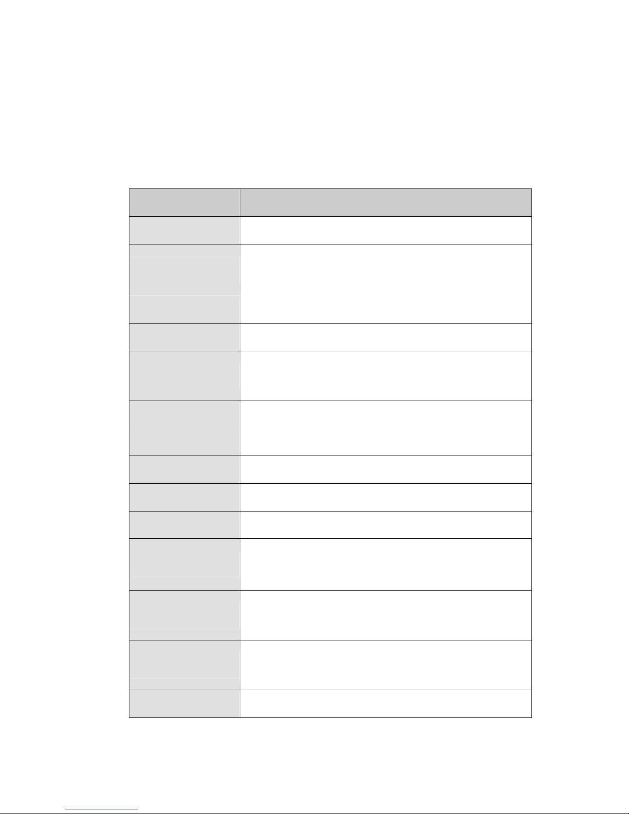
Specification 3308050
3308050
Form Factor
CPU
System Chipset
Display
Memory
BIOS
SSD
Super I/O
Audio
LAN
5.25” form factor
Embedded 1GHz VIA LUKE
Embedded 533MHz VIA LUKE
VIA VT8237R+
CRT integrated in VIA LUKE
Supports one 400MHz or 333MHz 184-pin DDR DIMM
module with a maximum capacity of 1GB
AMI BIOS Label
Compact Flash (CF)
W83697HG
AC'97 Codec Realtek ALC655
Dual RTL8110S
COM
USB2.0
IDE
Parallel Port
20
Five RS-232C
One RS-232/422/485
Four USB 1.1 or 2.0 onboard connectors support two devices
each
One 40-pin and one 44-pin IDE each connects to two Ultra
ATA33/66/100/133 IDE devices
One LPT port connector
Global American Inc.
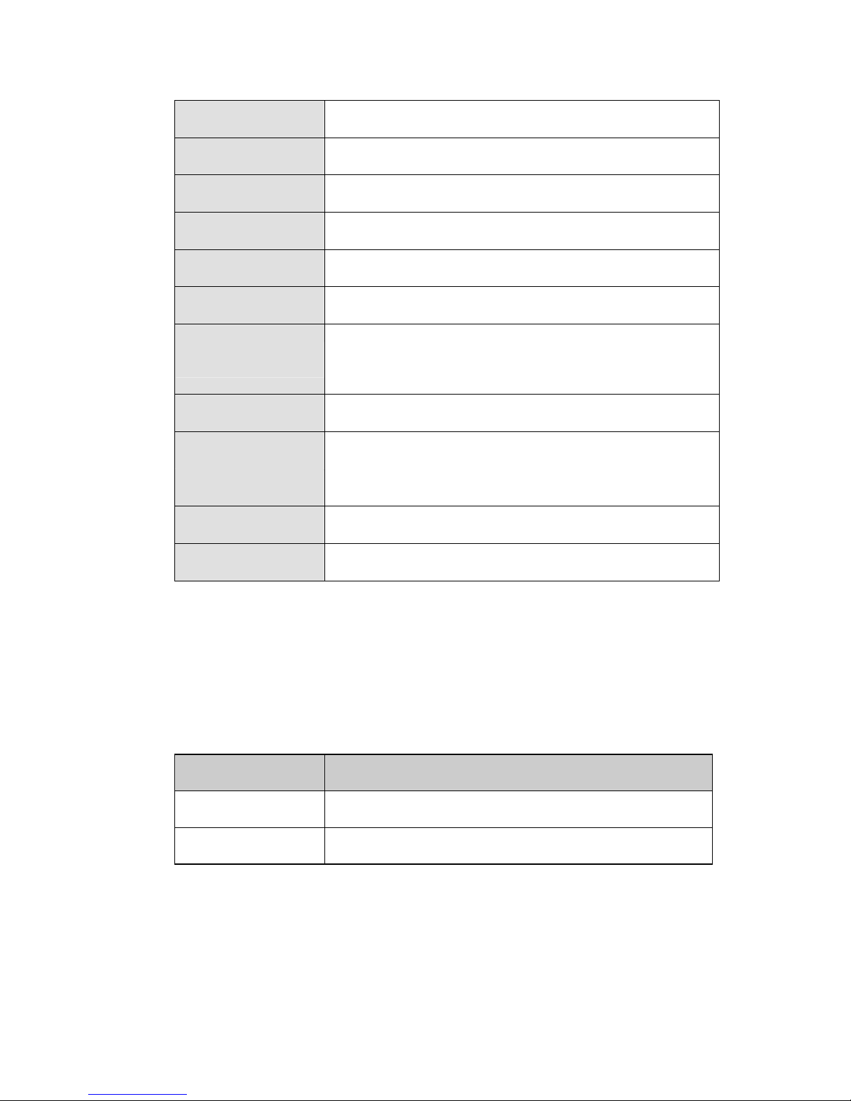
3308050
SA TA
KB/MS
WDT
IrDA
Digital I/O
Fan connector
Expansion
Power
Temperature
Humidity
Two SATA connectors with transfer rates up to 150MB/sec
One PS/2 connector
Software programmable 1-255 sec. by supper I/O
SIR / ASKIR
8-bit digital IO (4 input / 4 output) by super I/O
One CPU Fan
One PC/104-Plus interface
One PCI slot
+5V or +12V AT or ATX support
0ºC - 60ºC
5%~95% non-condensing
Dimensions
Weight (GW/NW)
Table 1-1: Technical Specifications
146.05mm x 203.2mm
1100g/500g
1.3.2 Optional 3907720 Daughterboard Technical Specifications
3907720 technical specifications are listed in Table 1-2. Detailed descriptions of each
specification can be found in Chapter 2 Detailed Specifications.
Specification POM-121IB
Chipset
Display Connector
Table 1-2: 3907720 Technical Specifications
VIA VT1631L
LVDS
21

3308050
THIS PAGE IS INTENTIONALLY LEFT BLANK
22
Global American Inc.

3308050
Chapter
2
2 Detailed Specifications
23
2.1 Overview
This chapter describes the specifications and onboard features of the 3308050 in
detail.
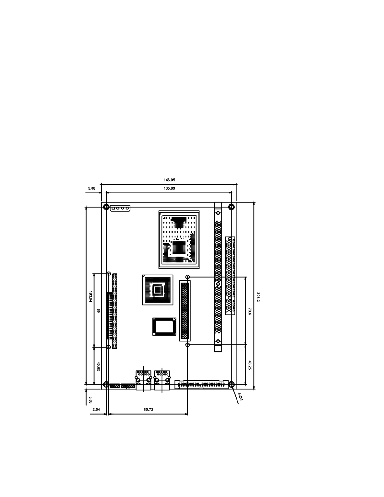
2.2 Board Dimensions
The dimensions of the board are listed below and shown in Figure 2-1:
Length: 203.2mm
Width: 146.05mm
3308050
Figure 2-1: 3308050 Dimension (mm)
24
Global American Inc.

The external interface connector panel dimensions are shown in Figure 2-2.
Figure 2-2: 3308050 External Interface Connector Dimensions (mm)
2.3 CPU Support
3308050
The 3308050 motherboard comes with a preinstalled 1GHz or 533MHz, ultra low
voltage (ULV) VIA® Luke processor. The new VIA 'Luke' CoreFusion Processing Platform
integrates the latest generation VIA Eden-N™ processor with the VIA CN400 Northbridge
in a single, low power package.
The Luke CoreFusion processor features include the following:
Rich Integration:- Highly integrated processing and digital media corelogic
combination delivers leading performance in a single, power-efficient,
space-saving package
S3 Graphics Unichrome Pro Graphics Core:- With an internal data flow
equivalent to what is available to the latest AGP 8X graphics cards,
Unichrome Pro has separate 128-bit data path between the Northbridge for
pixel data flow and texture/command access. Separate 128-bit 2D and 3 D
graphics engines ensure optimal performance for all multimedia,
entertainment, and productivity applications.
Flawless Digital Media Playback:- Unichrome Pro includes native support
for the most popular digital video and audio playback through hardware
MPEG-2/-4 acceleration and acclaimed VIA Vinyl Audio suite, delivering
spectacular playback for entertainm ent devices.
Maximum Display Flexibility:- Unichrome Pro with its optimized shared
memory architecture and high definition video support through the
25

Chromotion CE Video Display Engine, offers a breathtaking visual experience
for the latest HDTV format displays. Support for LVDS and DVI interfaces
enables complete flexibility for integration into a wide range of embedded and
personal electronics applications
Native Serial ATA:- T he VIA DriveStaion™ Controller Suite with native dual
channel Serial ATA co ntroller provides direct support for two 150MB/s Serial
ATA devices and the SATAlite™ interface expands support for two additional
SATA devices.
2.4 System Chipset
The 3308050 motherboard has a VIA VT8237R Plus Southbridge onboard. A
summary of the available Southbridge features is listed below. For more information on
3308050
this chipset please visit the VIA website.
VIA DriveStation™ Controller Suite
o Serial ATA
Full duplex high performance 150MB/s Dual Channel Serial ATA interface
Support for additional two Serial ATA devices through SATALite™ interface
o Parallel ATA 133
Supports up to four PATA devices
VIA Advanced Connectivity Suite
o USB 2.0 Controller
o Support for 8 USB 2.0/1.1 ports
Network Controller
o Enterprise Class 10/100Mbps Fast Ethernet MAC
PCI & LPC bus controllers
VIA Vinyl™ Audio
o VIA Vinyl integrated 5.1 surround sound
AC ’97 audio
VIA Six-TRAC codec
o VIA Vinyl Gold onboard 7.1 surround sound
24/96 resolution audio
VIA Envy24PT + VIA Six-TRAC Codec + additional DAC
o VIA Stylus Audio drivers
Integrated Sensaura technology
26
Global American Inc.

V-MAP Architecture
2.5 Data Flow
Figure 2-3 shows the data flow between the two onboard chipsets and other components
3308050
Full 3D gaming support
o Ultra V-Link
High throughput 1GB/s South Bridge/North Bridge interconnect
Supports new generation VIA North Bridges across all processor platforms
o 8X V-Link
High speed 533MB/s South Bridge/North Bridge interconnect
Supports current generation VIA North Bridges across all processor platforms
o VIA Hyperion 4in1 Unified Drivers
Optimized system performance and stability
installed on the motherboard and described in the following sections of this chapter.
Figure 2-3: Data Flow Block Diagram
27

2.6 Graphics Support
The LUKE processor comes with a S3 Chromotion graphics engine. The features listed
below are compatible with S3 Graphics' Chrome S20 Series processors:
Chromotion Video Acceleration:-
o WMV9 Motion Compensation H/W Acceleration – Reduces CPU
utilization when decoding Windows Media Video 9 (WMV9) files.
o MPEG-2 IDCT and Motion Compensation H/W Acceleration –
Reduces CPU utilization when decoding MPEG2 files.
Chromotion Hi-Def™ Support:-
o HDTV Formats – Supports all 18 DTV ATSC formats.
o Adaptive Per-Pixel De-Interlacing – Produces superior image quality for
3308050
both still and motion images using a high quality De-Interlacing proce ss.
o Video Deblocking – Removes blocking artifacts inherent in low bit rate
images.
o ChromoVision – Displays full screen video on secondary HDTV display
while a windows display of the video is on the primary CRT or DVI display.
o ChromoVision Modes with ChromeView Non-Linear Scaling – Scales
a standard 4:3 image to fill a wide-screen 16:9 display with excellent
image quality.
o PanelDrive – Eliminates blurring effects with motion video on panel
displays by increasing panel response time.
o ChromoColor – Provides adjustment controls for the brightness, contrast,
hue and saturation of the display of video.
Chromotion Video Image Controls:-
o ChromoColor Tonal Adjustment – Allows fine-tuning of luma values for
the video display with controls for black point and white point
enhancement.
o ArtisticLicense Effects – Allows high quality image enhancements;
including Sharpening, Soft Focus, Embossing, and Neon Edge effects.
28
Global American Inc.

3308050
2.7 Optional 3907720 LVDS Display Support
The 3308050 Motherboard supports LVDS displays. Using the 3907720 daughterboard
enables connectivity to 18-bit or 24-bit flat panel displays. The 3907720 comes with an
onboard VIA VT1631L Low Voltage Differential Signaling (LVDS) Transmitter. The VIA
VT1631L is designed to support pixel data transmissions from a Host to a Flat Panel
display ranging from VGA to UXGA resolutions. VIA VT1631 features are listed below.
Complies with Open LDI Specification for Digital Display Interfaces
25 to 85 MHz Input Clock Support
Supports VGA through UXGA Panel Resolution
Power-down mode <198uW max (TBD)
Two-wire Se rial Communication Interface up to 400KHz
Narrow Bus reduces cable size and cost
Up to 4.76 Gbps bandwidth in dual 24-bit RGB into Dual Pixel Out
applications
Up to 592Mbytes/sec bandwidth
Dual 12-bit double pumped digital input port
PLL requires no external components
Support both LVTTL and low voltage level input (Capable of 1.0 to 1.8V)
Programmable input clock and control strobe select
Compatible with TIA/EIA-644
2.24 to 2.75 supply voltage
TQFP-100 Thin Quad Flat package
2.8 Memory Support
The 3308050 has one 184-pin dual inline memory module (DIMM) socket and
supports one DDR DIMM with the following specifications:
Maximum RAM: 1GB
DIMM Transfer Rates: 400MHz or 333MHz
2.9 PCI Bus Interface Support
The PCI bus on the 3308050 Motherboard has the following features:
29

33MHz Revision 2.2 is implemented
Maximum throughput: 133MB/sec
One PCI REQ/GNT pair can be given higher arbitration priority (intende d for
external 1394 host controller)
64-bit addressing supported
2.10 Ethernet Controller
2.10.1 Introduction
The Realtek RTL8110S Ethernet controller combines a triple-speed IEEE 802.3 compliant
Media Access Controller (MAC) with a triple-speed Ethernet transceiver, 32-bit PCI bus
controller, and embedded memory. The device supports the PCI v2.2 bus interface for
host communications with power management, and is compliant with the IEEE 802.3
3308050
specification for 10/100Mbps Ethernet and the IEEE 802.3ab specification for 1000Mbps
Ethernet. It also supports an auxiliary power auto-detect function, and will auto-configure
related bits of the PCI power management registers in PCI configuration space.
2.10.2 Realtek RTL8110S Features
Realtek RTL8110S features are listed below
Integrated 10/100/1000 transceiver
Auto-Negotiation with Next page capability
Supports PCI 2.2, 32bit, 33/66MHz
Supports pair swap/polarity/skew correction
Crossover Detection & Auto-Correction
Wake-on-LAN and remote wake-up support
Microsoft® NDIS5 Checksum Offload (IP, TCP, UDP) and largesend offload
support
Supports Full Duplex flow control (IEEE 802.3x)
Fully compliant with IEEE 802.3, IEEE 802.3u, IEEE 802.3ab
Supports IEEE 802.1Q VLAN tagging
Serial EEPROM
3.3V signaling, 5V PCI I/O tolerant
Transmit/Receive FIFO (8K/64K) support
Supports power down/link down power saving
30
Global American Inc.
 Loading...