

Global American 3308040A, 3308040B, 3308040C, 3308040D, 3308040E User Manual
...
5_1/4" Embedded Controller
Version 1.0,
User’s Manual
3308040
August 2006

Copyrights
This manual is copyrighted and all rights are reserved. It does not allow any non authorization in
copied, photocopied, translated or reproduced to any electronic or machine readable form in
whole or in part without prior written consent from the manufacturer.
In general, the manufacturer will not be liable for any direct, indirect, special, incidental or
consequential damages arising from the use of inability to use the product or documentation, even
if advised of the possibility of such damages. The manufacturer keeps the rights in the subject to
change the contents of this manual without prior notices in order to improve the function design,
performance, quality and reliability. The author assumes no responsibility for any errors or
omissions, which may appear in this manual, nor does it make a commitment to update the
information contained herein.
Trademarks
Intel is a registered trademark of Intel Corporation.
Award is a registered trademark of Award Software, Inc.
All other trademarks, products and or product's name mentioned herein are mentioned for
identification purposes only, and may be trademarks and/or registered trademarks of their
respective companies or owners.

3308040 Motherboard
Table of Contents
1 INTRODUCTION................................................................................................... 13
1.1 3308040 O
1.1.1 3308040 Models .............................................................................................. 14
1.1.2 3308040 Applications...................................................................................... 14
1.1.3 3308040 Benefits ............................................................................................. 15
1.1.4 3308040 Features............................................................................................ 15
1.2 3308040 O
1.2.1 3308040 Connectors........................................................................................ 17
1.2.2 Technical Specifications................................................................................... 18
2 DETAILED SPECIFICATIONS........................................................................... 21
2.1 O
VERVIEW ............................................................................................................... 22
2.2 BOARD DIMENSIONS................................................................................................ 22
2.2.1 CPU Support.................................................................................................... 23
2.2.2 Supported Pentium® M CPUs......................................................................... 23
2.2.3 Supported Celeron® M CPUs ......................................................................... 24
2.3 ONBOARD CHIPSETS ................................................................................................ 25
2.3.1 Northbridge and Southbridge Chipsets ........................................................... 25
VERVIEW................................................................................................ 14
VERVIEW................................................................................................ 16
2.3.2 Intel® 852GM Northbridge Chipset................................................................. 25
2.3.3 Intel® ICH4 Southbridge Chipset ....................................................................26
ATA FLOW.............................................................................................................. 26
2.4 D
2.5 GRAPHICS SUPPORT ................................................................................................. 28
2.6 MEMORY SUPPORT................................................................................................... 29
2.7 PCI BUS INTERFACE SUPPORT ................................................................................. 29
2.8 GBE ETHERNET....................................................................................................... 29
2.9 DRIVE INTERFACES .................................................................................................. 30
2.9.1 SATA Drives..................................................................................................... 30
2.9.2 IDE HDD Interfaces........................................................................................ 30
2.9.3 Floppy Disk Drive (FDD)................................................................................ 30
2.9.4 CompactFlash Support .................................................................................... 31
2.11 REAL TIME CLOCK................................................................................................. 31
3

2.12 SYSTEM MONITORING............................................................................................ 31
2.13 INFRARED DATA ASSOCIATION (IRDA) INTERFACE................................................ 31
2.14 USB INTERFACES................................................................................................... 32
2.15 BIOS ..................................................................................................................... 32
2.16 OPERATING TEMPER ATURE AND TEMPERATURE CONTROL..................................... 32
2.17 AUDIO CODEC........................................................................................................ 32
2.18 POWER CONSUMPTION........................................................................................... 34
2.19 PACKAGED CONTENTS AND OPTIONAL ACCESSORY ITEMS..................................... 34
2.19.1 Package Contents........................................................................................... 34
2.19.2 Optional Accessory Items............................................................................... 35
3 CONNECTORS AND JUMPERS .........................................................................37
3.1 PERIPHERAL INTERFACE CONNECTORS .................................................................... 38
3.1.1 3308040 Layout............................................................................................... 38
3.1.2 Peripheral Interface Connectors ..................................................................... 39
3.1.3 Rear Panel Connectors.................................................................................... 41
3.1.4 Onboard Jumpers............................................................................................. 41
3.2 INTERNAL PERIPHERAL CONNECTORS...................................................................... 41
3.2.1 Power Connector............................................................................................. 42
3.2.2 ATX PS_ON Connector.................................................................................... 43
3.2.3 Audio Connector .............................................................................................. 44
3.2.4 CompactFlash Connector................................................................................ 45
3.2.5 Digital Input/Output (DIO) Connector............................................................ 46
3.2.6 Digital Visual Interface (DVI) Connector........................................................ 48
3.2.7 Fan Connector................................................................................................. 49
3.2.8 Floppy Disk Connector.................................................................................... 50
3.2.9 Front Panel Connector.................................................................................... 52
3.2.10 IDE Connector (Primary).............................................................................. 53
3.2.11 IDE Connector (Secondary)........................................................................... 55
3.2.12 Inverter Power Connector ............................................................................. 56
3.2.13 IR Interface Connector .................................................................................. 57
3.2.14 Keyboard/Mouse Connector.......................................................................... 59
3.2.15 LCD LVDS Connector ................................................................................... 60
3.2.16 Parallel Port Connector ................................................................................ 62
3.2.17 RS-232 Serial Port Connectors...................................................................... 63
3.2.18 RS-232/422/485 Serial Port Connector......................................................... 64
4 Global American Inc.

3308040 Motherboard
3.2.19 SATA Drive Connectors ................................................................................. 66
3.2.20 Internal USB Connectors............................................................................... 67
3.2.21 VGA Connector (Internal) ............................................................................. 68
3.3 E
XTERNAL (REAR PANEL) CONNECTORS ................................................................. 69
3.3.1 LAN Connectors............................................................................................... 69
3.4 ONBOARD JUMPERS ................................................................................................. 71
3.4.1 Clear CMOS Jumper........................................................................................ 72
3.4.2 CF Card Setup ................................................................................................. 73
3.4.3 LCD Voltage Setup Jumper.............................................................................. 75
3.4.4 COM4 Setup Jumper (RS-232/422/485).......................................................... 76
4 INST ALLA TION AND CONFIGURA TION ....................................................... 79
4.1 ANTI-STATIC PRECAUTIONS...................................................................................... 80
4.2 INSTALLATION CONSIDERATIONS ............................................................................. 80
4.2.1 Installation Notices.......................................................................................... 80
4.3 UNPACKING.............................................................................................................. 81
4.3.1 Unpacking Precautions.................................................................................... 81
4.3.2 Checklist........................................................................................................... 82
4.4 3308040 MOTHERBOARD INSTALLATION................................................................. 82
4.4.1 CPU Installation.............................................................................................. 84
4.4.2 Cooling Kit (CF-479B-RS ) Installation.......................................................... 86
4.4.3 DIMM Module Installation.............................................................................. 88
4.4.3.1 Purchasing the Memory Module............................................................... 88
4.4.3.2 DIMM Module Installation....................................................................... 88
4.4.4 Peripheral Device Connection......................................................................... 89
4.4.4.1 IDE Disk Drive Connector (IDE1) ........................................................... 90
HASSIS INSTALLATION ........................................................................................... 90
4.5 C
4.6 REAR PANEL CONNECTORS ...................................................................................... 91
4.6.1 Ethernet Connection ........................................................................................ 91
A WATCHDOG TIMER.............................................................................................93
B ADDRESS MAPPING..............................................................................................97
C EXTERNAL AC’97 AUDIO CODEC....................................................................101
D RAID SETUP............................................................................................................107
5 Global American Inc.

3308040
THIS PAGE IS INTENTIONALLY LEFT BLANK
6
Global American Inc.

List of Figures
Figure 1-1: 3308040 Overview ...................................................................................16
Figure 1-2: 3308040 Solder Side Overview ..............................................................16
Figure 2-1: 3308040 Dimension (mm).......................................................................22
Figure 2-2: Data Flow Block Diagram........................................................................27
Figure 3-1: Connector and Jumper Locations.........................................................38
Figure 3-2: Connector and Jumper Locations (Solder Side)..................................39
Figure 3-3: Power Connector Location.....................................................................42
Figure 3-4: ATX PS_ON Connector Location...........................................................43
Figure 3-5: Audio Connector Location......................................................................44
Figure 3-6: CompactFlash Connector Location.......................................................45
Figure 3-7: DIO Connector Connector Locations....................................................47
Figure 3-8: DVI Connector Location..........................................................................48
Figure 3-9: Fan Connector Location .........................................................................50
Figure 3-10: FDD Connector Location ......................................................................51
Figure 3-11: Front Panel Connector Locations........................................................52
Figure 3-12: Primary IDE Device Connector Locations...........................................54
Figure 3-13: Secondary IDE Device Connector Locations......................................55
Figure 3-14: Inverter Connector Locations ..............................................................57
Figure 3-15: IR Connector Pinout Locations............................................................58
Figure 3-16: Keyboard/Mouse Connector Location.................................................59
Figure 3-17: LVDS Connector Locations..................................................................61
Figure 3-18: Parallel Port Connector Location.........................................................62
Figure 3-19: RS-232 Serial Port Connector Locations ............................................63
Figure 3-20: RS-232/422/485 Serial Port Connector Location................................65
Figure 3-21: SATA Drive Connector Locations........................................................66
Figure 3-22: USB Connector Pinout Locations........................................................67
Figure 3-23: VGA Connector Location......................................................................68
Figure 3-24: 3308040 Rear Panel...............................................................................69
Figure 3-25: RJ-45 Ethernet Connector ....................................................................70
7 Global American Inc.

3308040 Motherboard
Figure 3-26: CLR_CMOS Pinout Locations ..............................................................73
Figure 3-27: JP5 Pinout Locations............................................................................74
Figure 3-28: JP3 Pinout Locations............................................................................76
Figure 3-29: COM4 Setup Jumper Pinout Locations...............................................77
Figure 4-1: Make sure the CPU socket retention screw is unlocked.....................84
Figure 4-2: Lock the CPU Socket Retention Screw.................................................85
Figure 4-3: GAI 2107703 Cooling Kit .........................................................................86
Figure 4-4: Cooling Kit Support Bracket...................................................................87
Figure 4-5: Connect the cooling fan cable ...............................................................87
Figure 4-6: DIMM Module Installation........................................................................89
8

List of Tables
Table 1-1: 3308040 Model Specifications.................................................................14
Table 1-2: Technical Specifications ..........................................................................18
Table 2-1: Supported Pentium® M CPUs..................................................................23
Table 2-2: Supported Celeron® M CPUs...................................................................24
Table 2-3: Power Consumption .................................................................................34
Table 3-1: Peripheral Interface Connectors..............................................................39
Table 3-2: Rear Panel Connectors.............................................................................41
Table 3-3: Onboard Jumpers .....................................................................................41
Table 3-4: Power Connector Pinouts ........................................................................43
Table 3-5: ATX PS_ON Connector Pinouts...............................................................44
Table 3-6: Audio Connector Pinouts.........................................................................45
Table 3-7: CompactFlash Connector Pinouts ..........................................................46
Table 3-8: DIO Connector Connector Pinouts..........................................................47
Table 3-9: DVI Connector Connector Pinouts..........................................................48
Table 3-10: Fan Connector Pinouts...........................................................................50
Table 3-11: FDD Connector Pinouts..........................................................................51
Table 3-12: Front Panel Connector Pinouts .............................................................53
Table 3-13: Primary IDE Connector Pinouts.............................................................54
Table 3-14: Secondary IDE Connector Pinouts........................................................55
Table 3-15: Inverter Power Connector Pinouts........................................................57
Table 3-16: IR Connector Pinouts..............................................................................58
Table 3-17: Keyboard/Mouse Connector Pinouts....................................................60
Table 3-18: LCD LVDS Connector Pinouts...............................................................61
Table 3-19: Parallel Port Connector Pinouts............................................................63
Table 3-20: RS-232 Serial Port Connector Pinouts..................................................64
Table 3-21: RS-232/RS-422/RS-485 Serial Port Connector Pinouts.......................65
Table 3-22: SATA Drive Connector Pinouts.............................................................66
Table 3-23: USB Port Connector Pinouts .................................................................68
Table 3-24: VGA Connector Pinouts .........................................................................69
9 Global American Inc.

3308040 Motherboard
Table 3-25: LAN Pinouts.............................................................................................70
Table 3-26: RJ-45 Ethernet Connector LEDs............................................................70
Table 3-27: Jumpers....................................................................................................71
Table 3-28: Clear CMOS Jumper Settings ................................................................72
Table 3-29: CF Card Setup Jumper Settings............................................................74
Table 3-30: JP3 Jumper Settings...............................................................................75
Table 3-31: COM4 Setup Jumper Settings................................................................76
Table 4-1: GAI Provided Cables.................................................................................89
10

3308040 Motherboard
Glossary
AC ’97 Audio Codec 97
ACPI Advanced Configuration and
Power Interface
APM Advanced Power Management
ARMD ATAPI Removable Media Device
ASKIR Shift Keyed Infrared
ATA Advanced Technology
Attachments
BIOS Basic Input/Output System
CFII CompactFlash Type 2
CMOS Complementary Metal Oxide
Semiconductor
CPU Central Processing Unit
Codec Compressor/Decompressor
COM Serial Port
DAC Digital to Analog Converter
DDR Double Data Rate
HDD Hard Disk Drive
IDE Integrated Data Electronics
I/O Input/Output
ICH4 I/O Controller Hub 4
L1 Cache Level 1 Cache
L2 Cache Level 2 Cache
LCD Liquid Crystal Display
LPT Parallel Port Connector
LVDS Low Voltage Differential Signaling
MAC Media Access Controller
OS Operating System
PCI Peripheral Connect Interface
PIO Programmed Input Output
PnP Plug and Play
POST Power On Self Test
RAM Random Access Memory
SATA Serial ATA
DIMM Dual Inline Memory Module
DIO Digital Input/Output
DMA Direct Memory Access
EIDE Enhanced IDE
EIST Enhanced Int el SpeedStep
Technology
FDD Floppy Disk Drive
FDC Floppy Disk Connector
FFIO Flexible File Input/Output
FIFO First In/First Out
FSB Front Side Bus
IrDA Infrared Data Association
S.M.A.R.T Self Monitoring Analysis and
Reporting Technology
SPD Serial Presence Detect
S/PDI Sony/Philips Digital Interface
SDRAM Synchronous Dynamic Random
Access Memory
SIR Serial Infrared
UART Universal Asynchronous
Receiver-transmitter
USB Universal Serial Bus
VGA Video Graphics Adapter
11

THIS PAGE IS INTENTIONALLY LEFT BLANK
12 Global American Inc.

3308040 Motherboard
Chapter
1
1 Introduction
13
1.1 3308040 Overview
The 5.25” 3308040 socket 479 Pentium M and Celeron M single board computer
(SBC) is fully equipped with advanced multi-mode I/Os. The 3308040 is designed
for system manufacturers, integrators, and VARs that want performance, reliability, and
quality at a reasonable price.
1.1.1 3308040 Models
The 3308040 series has eight models:
3308040A
3308040B
3308040C
3308040D
3308040E
3308040F
3308040G
3308040H
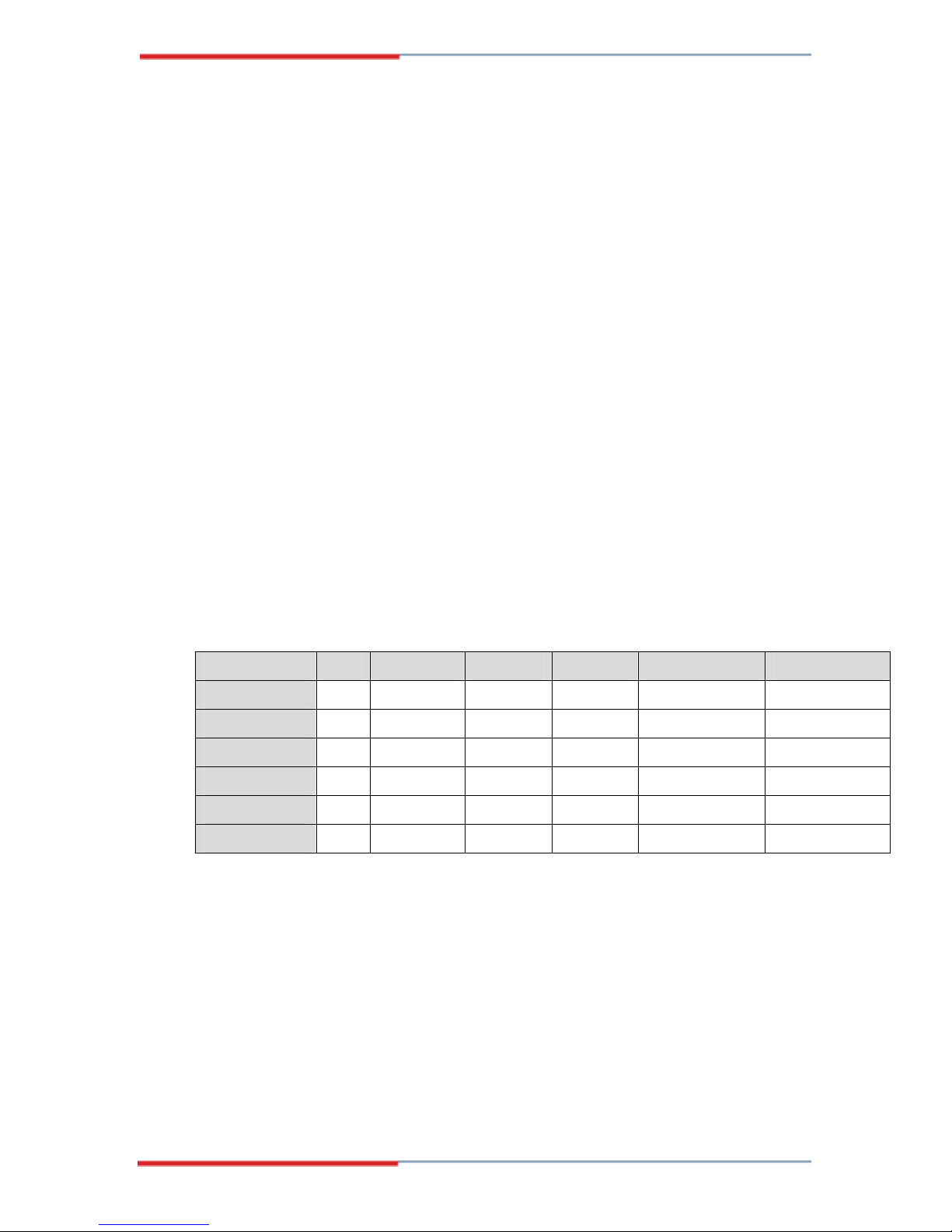
The specifications for the four models are show in Table 1-1.
3308040 A B C D E F
Onboard CPU NO CM600Z CM1GZ NO CM600Z CM1GZ
CRT/LCD YES YES YES YES YES YES
Dual GbE YES YES YES YES YES YES
SATA YES YES YES YES YES YES
Audio YES YES YES YES YES YES
DVI Function NO NO NO YES YES YES
Table 1-1: 3308040 Model Specifications
CM600Z : Intel Celeron M 600MHz / zero cache CPU
CM1GZ : Intel Celeron M 1GMHz / zero cache CPU
1.1.2 3308040 Applications
The 3308040 is designed for applications in the following areas:
14 Global American Inc.

Industrial PC applications
Human Machine Interface (HMI) applications
Marine, GPS and transportation applications
Financial, retail and kiosk applications
1.1.3 3308040 Benefits
Some of the 3308040 benefits include:
Low power, high performance
Flexible dual display options
Multiple storage option integration including
o
o 44 Pin IFM or 2.5” HDD (hard disk drive)
3308040 Motherboard
40 Pin IFM or 3.5” HDD (hard disk drive)
o Dual SATA ports with RAID 0 and RAID 1 support
o CFII (CompactFlash) support
o Floppy disk drive (FDD) support
Mini PCI
SATA RAID support
1.1.4 3308040 Features
Some of the 3308040 features are listed below:
5.25” form factor
RoHS compliant
Socket 479 Intel® Pentium M/Celeron M processors supported
Dual-independent display functionality
Maximum front side bus (FSB) speed up to 400MHz supported
Up to 2GB of 266MHz of DDR memory supported
Two high performance gigabit Ethernet (GbE) controllers onboard
Two SATA channels with transfer rates up to 150MB/s onboard
Six USB 2.0 devices onboard
Integrated audio
15

1.2 3308040 Overview
Figure 1-1: 3308040 Overview
Figure 1-2: 3308040 Solder Side Overview
16 Global American Inc.

1.2.1 3308040 Connectors
The 3308040 has the following connectors onboard:
1 x Power connector
1 x PS_ON power connector
1 x Audio connector
1 x CompactFlash (CF) connector (solder side)
1 x Digital input/output connector
1 x DVI connector
1 x Fan connector
1 x Floppy disk connector
1 x Front panel connector
2 x IDE Interface connectors (40-pin and 44-pin)
3308040 Motherboard
1 x Inverter power connector
1 x IR interface connector
1 x Keyboard/mouse connector
1 x LCD LVDS interface connector
1 x PCI slot
1 x Parallel port connector
1 x RS-232/422/485 serial port connector
3 x RS-232 serial port connectors
2 x SATA connectors
3 x USB connectors
1 x VGA connector
2 x 184-pin DIMM sockets
The 3308040 has the following connectors on the board rear panel:
2 x Ethernet connectors
The 3308040 has the following onboard jumpers:
Clear CMOS
CF card setup
17

1.2.2 Technical Specifications
3308040 technical specifications are listed in Table 1-2. Detailed descriptions of
each specification can be found in Chapter 2 Detailed Specifications.
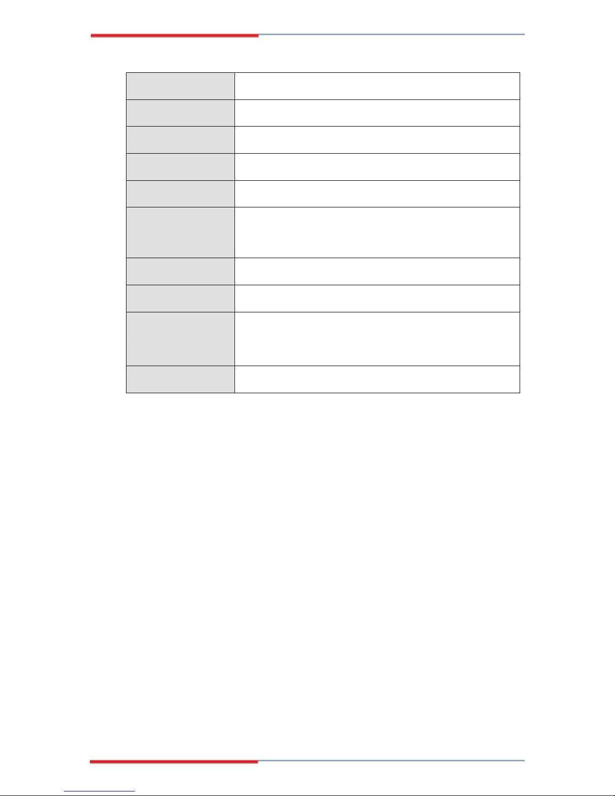
Specification 3308040
Form Factor
CPU
Northbridge Chipset
Southbridge Chipset
Display
Memory
BIOS
SSD
Super I/O
Audio
5.25” form factor
Intel socket 479 Pentium M (up to 2.1 GHz)
Intel socket 479 Celeron M (up to 1.7 GHz)
Intel 852GM
ICH4
Intel Extreme Graphics 2 (integrated into Northbridge)
Supports two 1GB DDR266 184-pin DIMM modules
AMI BIOS Label
CompactFlash (CF)
W83627HG
Realtek ALC655 AC'97 Codec
LAN
COM
USB2.0
IDE
Parallel Port
SA TA
18 Global American Inc.
Dual RTL8110SC
3 x RS-232C
1 x RS-232/422/485
3 x USB 1.1 or 2.0 onboard connectors support two devices
each
1 x 40-pin IDE connects to two Ultra ATA33/66/100 devices
1 x 44-pin IDE connects to two Ultra ATA33/66/100 devices
1 x LPT port connector
2 x SATA connectors with transfer rates up to 150MB/sec
3308040 Motherboard
KB/MS
WDT
IrDA
Digital I/O
Fan connector
Expansion
Power
Temperature
Humidity
Dimensions
PS/2 connector
Software programmable 1-255 sec. by super I/O
SIR / ASKIR
4 input / 4 output by super I/O
1x3 pin for CPU Fan
1x mini PCI slot
1 x PCI slot
+5V/+12V, AT/ATX support
0ºC - 60ºC
5%~95% non-condensing
146.05mm x 203.2mm
Weight (GW/NW)
Table 1-2: Technical Specifications
1000g/400g
19

THIS PAGE IS INTENTIONALLY LEFT BLANK
20 Global American Inc.

3308040 Motherboard
Chapter
2
2 Detailed Specifications
21

2.1 Overview
This chapter describes the specifications and onboard features of the N3308040 in
detail.
2.2 Board Dimensions
The dimensions of the board are listed below:
Length: 203.2mm
Width: 146.05mm
Figure 2-1: 3308040 Dimension (mm)
22 Global American Inc.
2.2.1 CPU Support
NOTE:
3308040 Motherboard
The 3308040B and the 3308040E
have a preinstalled zero cache Intel Celeron M 600MHz on board.
The 3308040C and the 3308040F have
a preinstalled zero cache Intel Celeron
The 3308040 supports normal voltage, low voltage (LV
mobile (M) Intel® Pentium® M processors and Intel® Celeron® M processors
M 1GMHz on board.
) and ultra low voltage (ULV)
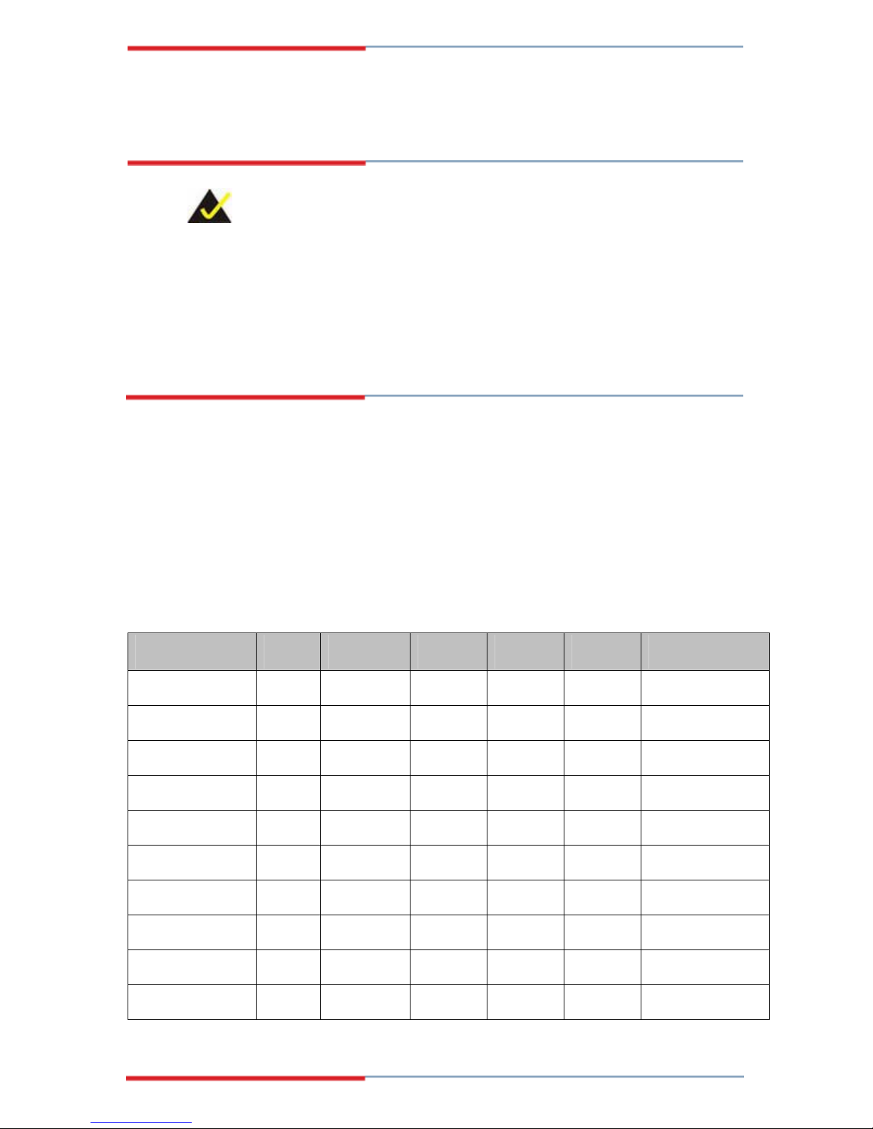
2.2.2 Supported Pentium® M CPUs
Table 2-1 lists the Intel® Pentium® M processors supported by the 3308040 CPU
board. All the Intel® Pentium® M processors support Enhanced Intel SpeedStep®
Technology.
Processor Number Power Architecture L2 Cache Speed FSB Execute Disable Bit
778 LV 90nm 2MB 1.60GHz 400MHz Yes
765 Normal 90nm 2MB 2.10GHz 400MHz No
758 LV 90nm 2MB 1.50GHz 400MHz Yes
755 Normal 90nm 2MB 2GHz 400MHz No
753 ULV 90nm 2MB 1.20GHz 400MHz Yes
745 Normal 90nm 2MB 1.80GHz 400MHz No
738 LV 90nm 2MB 1.40GHz 400MHz No
735 Normal 90nm 2MB 1.70GHz 400MHz No
733J ULV 90nm 2MB 1.10GHz 400MHz Yes
733 ULV 90nm 2MB 1.10GHz 400MHz No
23
725 ULV 90nm 2MB 1.60GHz 400MHz No
723 ULV 90nm 2MB 1GHz 400MHz No
718 LV 130nm 1MB 1.30GHz 400MHz No
Table 2-1: Supported Pentium® M CPUs
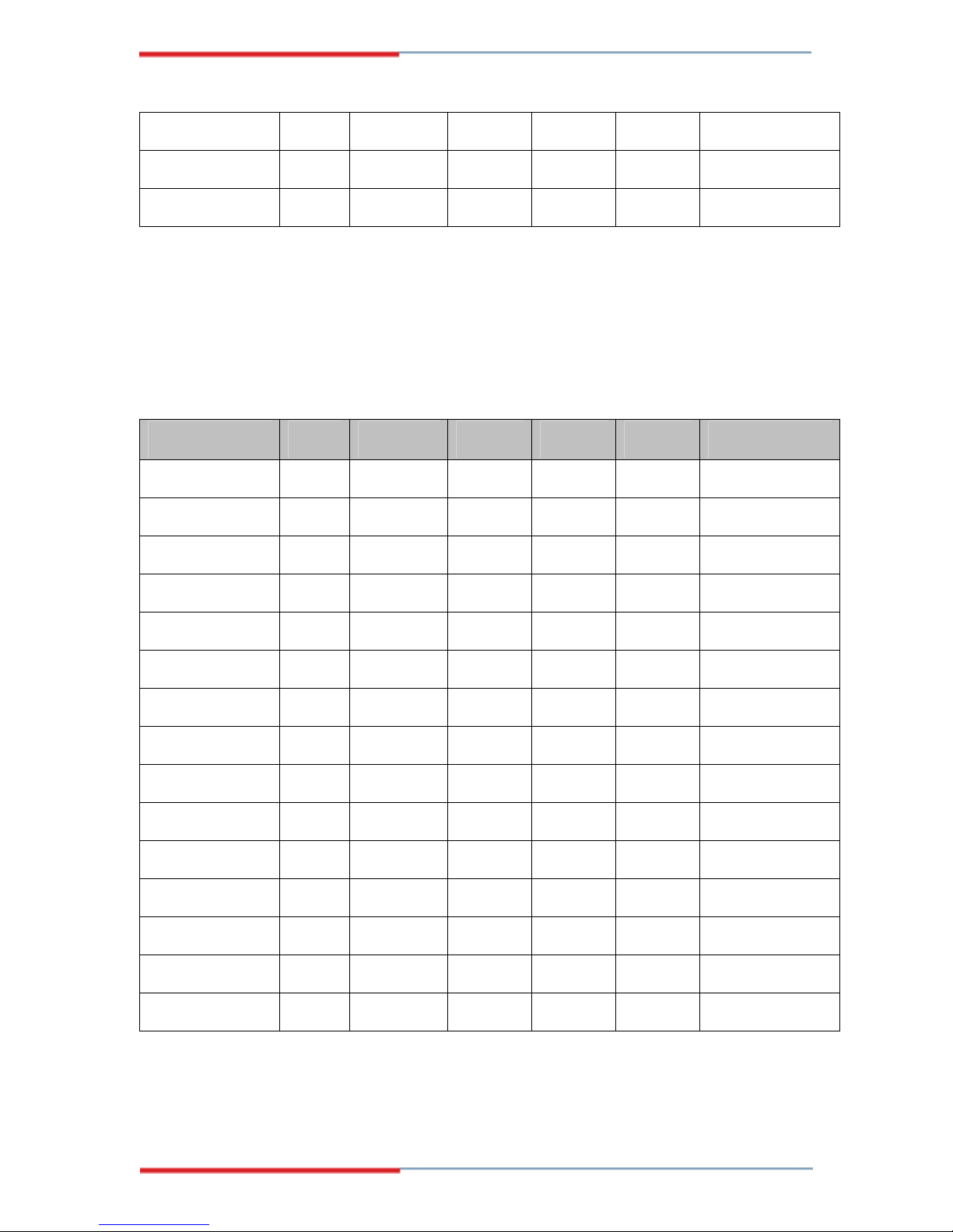
2.2.3 Supported Celeron® M CPUs
Table 2-2 lists the Intel® Celeron® M processors supported by the 3308040 CPU
board.
Processor Number Power Architecture L2 Cache Speed FSB Execute Disable Bit
390 Normal 90nm 1MB 1.70GHz 400MHz Yes
383 ULV 90nm 1MB 1GHz 400MHz Yes
380
373
370
360J
360
353
350J
350
340
333
330
320
Normal
ULV
Normal
Normal
Normal
ULV
Normal
Normal
Normal
ULV
Normal
Normal
90nm 1MB 1.60GHz 400MHz Yes
90nm 512KB 1GHz 400MHz Yes
90nm 1MB 1.50GHz 400MHz Yes
90nm 1MB 1.40GHz 400MHz Yes
90nm 1MB 1.40GHz 400MHz No
90nm 512KB 900MHz 400MHz No
90nm 1MB 1.30GHz 400MHz Yes
90nm 1MB 1.30GHz 400MHz No
130nm 512KB 1.50GHz 400MHz No
130nm 512KB 900MHz 400MHz No
130nm 512KB 1.40GHz 400MHz No
130nm 512KB 1.30GHz 400MHz No
310
Table 2-2: Supported Celeron® M CPUs
Normal
24 Global American Inc.
130nm 512KB 1.20GHz 400MHz No

2.3 Onboard Chipsets
2.3.1 Northbridge and Southbridge Chipsets
The following chipsets are preinstalled on the board:
3308040 Motherboard
Northbridge: Intel
Southbridge: Intel
®
852GM
®
ICH4
The following two sections (Section 2.3.2 and Section 2.3.3) list some of the features of
®
the Intel
852GM and the Intel® ICH4 chipsets. For more information on these two
chipsets please refer to the Intel website.
2.3.2 Intel® 852GM Northbridge Chipset
The Intel 852GM northbridge chipset comes with the following features:
The Intel 852GM chipset is designed, validated, and optimized for the Mobile
Intel Celeron processor and Intel Celeron processor with Intel® NetBurst®
micro-architecture
400 MHz system bus delivers a high-bandwidth connection between the
processor and the platform
Supports integrated graphics utilizing Intel® Extreme Graphics 2 technology
Advanced packaging technology and industry leading electrical design
innovations deliver long-term system reliability over wide operating conditions
Three USB host controllers provide high performance peripherals with 480
Mbps of bandwidth, while enabling support for up to six USB 2.0 ports.
The on-chip AC ’97 implementation delivers 20-bit audio for enhanced so und
quality and full surround-sound capability.
LAN Connect Interface (LCI) provides flexible network solutions such as
10/100 Mbps Ethernet and 10/100 Mbps Ethernet with LAN manageability
Dual Ultra ATA/100 controll ers, coupl ed with the Intel® Application
Accelerator – a performance software p ackage – support faster IDE transfers
to storage devices
Intel Application Accelerator software provides additional performance over
native ATA drivers by improving I/O transfer rates and enabling faster O/S
load time, resulting in accelerated boot times
25

Communication and Network Riser (CNR) offers flexibility in system
configuration with a baseline feature set that can be upgraded with an audio
card, modem card, or network card
Embedded lifecycle support
Integrated graphics
2.3.3 Intel® ICH4 Southbridge Chipset
The ICH4 southbridge chipset comes with the following features, functions and
capabilities:
PCI Local Bus Specification, Revision 2.2-compliant with support for 33 MHz
PCI operations.
PCI slots (supports up to 6 Req/Gnt pairs)
ACPI Power Management Logic Support
Enhanced DMA controller, Interrupt controller, and timer functions
Integrated IDE controller supports Ultra ATA100/66/33
USB host interface with support for 6 USB ports; 3 UHCI host controllers; 1
Integrated LAN controller
System Management Bus (SMBus) Specification, Version 2.0 with additional
Supports Audio Codec ’97, Revision 2.3 specification (a.k.a., AC ’97
Low Pin Count (LPC) interface
Firmware Hub (FWH) interface support
Alert On LAN* (AOL) and Alert On LAN 2* (AOL2)
2.4 Data Flow
Figure 2-2 shows the data flow between the two onboard chipsets and other components
installed on the motherboard and described in the following sections of this chapter.
EHCI high-speed USB 2.0 Host controller
support for I
2
C devices
Component Specification, Revision 2.3) Link for Audio and Telephony codecs
(up to seven channels)
26 Global American Inc.

3308040 Motherboard
Figure 2-2: Data Flow Block Diagram
27

2.5 Graphics Support
Features of the Intel Extreme Graphics 2 technology integrated on the Intel 852GM
northbridge chipset are listed below.
Enhanced 2D 256-bit internal path:
o 8/16/32bpp
o DirectDraw*, GDI, GDI+
o Anti-aliased text support
o Alpha blending
o Alphas stretch blitter
o Hardware alpha blended RGB cursor
o Color space conversion
o 5x2 overlay support
o Rotate, scale and translate operations
High-performance 3D 256-bit internal path:
o 32bpp/ 24ZorW/ 8 Stencil
o DX7*/DX8*/OGL*1.1
o DXTn texture compression
o Up to 4 textures / pixel on a single pass
o Cubic reflection map
o Embossed/DOT3 bump mapping
o Multi-texture
o DOT3 bump-mapping
o Point sprites
Video and Display DirectShow*/DirectVA*:
o Hardware motion compensation support for DVD playback
o 4x2 overlay filter
o 350 MHz DAC frequency
o Maximum DVO pixel rate of up to 330MP/s
o Flat panel monitors and TV-out support via AGP Digital Display (ADD)
cards
o 350 MHz DAC for 1800x1440 @ 85Hz max CRT resolution or
2048x1536@60Hz max FP resolution
o Synchronous display for dual monitor capabilities
o 350MHz RAMDAC for up to QXGA analog monitor support
28 Global American Inc.

o Dual DVO ports for up to QXGA digital display support
o Multiple display types (LVDS, DVI, TV-out, CRT)
2.6 Memory Support
The 3308040 has two 184-pin dual inline memory module (DIMM) sockets and
supports up to two un-buffered DDR DIMMs with the following specifications:
Maximum RAM: 2GB (1GB module in each slot)
DIMM Transfer Rates: 266MHz
2.7 PCI Bus Interface Support
The PCI bus on the 3308040 has the following features:
3308040 Motherboard
33MHz Revision 2.2 is implemented
Maximum throughput: 133MB/sec
One PCI REQ/GNT pair can be given higher arbitration priority (intende d for
external 1394 host controller)
2.8 GbE Ethernet
The 3308040 has two RTL8110SC GbE Ethernet controllers onboard. The technical
features of these controllers are listed below.
Integrated 10/100/1000 transceiver
Auto-Negotiation with Next page capability
Supports PCI 2.3, 32bit, 33/66MHz
Supports pair swap/polarity/skew correction
Crossover Detection & Auto-Correction
Wake-on-LAN and remote wake-up support
Microsoft® NDIS5 Checksum Offload (IP, TCP, UDP) and largesend offload
support
Supports Full Duplex flow control (IEEE 802.3x)
Fully compliant with IEEE 802.3, IEEE 802.3u, IEEE 802.3ab
Supports IEEE 802.1Q VLAN tagging
Serial EEPROM
3.3V signaling, 5V PCI I/O tolerant
29

Transmit/Receive FIFO (8K/64K) support
Supports power down/link down power saving
2.9 Drive Interfaces
The 3308040 can support the following drive interfaces.
2 x SATA drives
4 x IDE devices
1 x FDD
1 x CFII card
2.9.1 SATA Drives
The 3308040 supports two, first generation SATA drives with transfer rates of up to
150MB/s
2.9.2 IDE HDD Interfaces
The 3308040 southbridge chipset IDE controller supports up to two HDDs with the
following specifications:
Supports PIO IDE transfers up to 16MB/s
Supports the following Ultra ATA devices:
o Ultra ATA/100, with data transfer rates up to 100MB/s
o Ultra ATA/66, with data transfer rates up to 66MB/s
o Ultra ATA/33, with data transfer rates up to 33MB/s
2.9.3 Floppy Disk Drive (FDD)
The 3308040 supports a single FDD. The following FDD formats are compatible
with the board.
5.25”: 360KB and 1.2MB
3.5”: 720KB, 1.44MB and 2.88MB
30 Global American Inc.
 Loading...