

Global American 3307880 User Manual

Single Board Computer
Version 1.0,
User’s Manual
3307880
October 2006

Copyrights
This manual is copyrighted and all rights are reserved. It does not allow any non authorization in
copied, photocopied, translated or reproduced to any electronic or machine readable form in
whole or in part without prior written consent from the manufacturer.
In general, the manufacturer will not be liable for any direct, indirect, special, incidental or
consequential damages arising from the use of inability to use the product or documentation, even
if advised of the possibility of such damages. The manufacturer keeps the rights in the subject to
change the contents of this manual without prior notices in order to improve the function design,
performance, quality and reliability. The author assumes no responsibility for any errors or
omissions, which may appear in this manual, nor does it make a commitment to update the
information contained herein.
Trademarks
Intel is a registered trademark of Intel Corporation.
Award is a registered trademark of Award Software, Inc.
All other trademarks, products and or product's name mentioned herein are mentioned for
identification purposes only, and may be trademarks and/or registered trademarks of their
respective companies or owners.

3307880 PCI CPU Card
Table of Contents
1 INTRODUCTION................................................................................................... 15
1.1 33078880 CPU B
1.1.1 3307880 CPU Board Applications.................................................................. 16
1.1.2 3307880 CPU Board Benefits ......................................................................... 16
1.1.3 3307880 CPU Board Features ........................................................................ 16
1.2 3307880 CPU BOARD OVERVIEW ........................................................................... 17
1.2.1 3307880 CPU Board Connectors..................................................................... 17
1.2.2 Technical Specifications: ................................................................................. 19
2 DETAILED SPECIFICATIONS........................................................................... 21
2.1 OVERVIEW ............................................................................................................... 22
2.2 CPU SUPPORT.......................................................................................................... 22
2.2.1 AMD® Geode™ LX 800 500MHz Specifications............................................. 22
2.2.2 AMD® Geode™ LX 800 500MHz Power Management................................... 22
2.3 SYSTEM CHIPSET ..................................................................................................... 23
2.4 DATA FLOW.............................................................................................................. 24
2.5 GRAPHICS SUPPORT ................................................................................................. 24
2.6 MEMORY SUPPORT................................................................................................... 26
OARD OVERVIEW ......................................................................... 16
2.7 PCI BUS INTERFACE SUPPORT ................................................................................. 26
2.8 ETHERNET CONTROLLER SPECIFICATIONS ............................................................... 26
2.8.1 Overview.......................................................................................................... 26
2.8.2 Features ........................................................................................................... 27
RIVE INTERFACES .................................................................................................. 27
2.9 D
2.9.1 SATA Drives..................................................................................................... 27
2.9.2 IDE HDD Interfaces........................................................................................ 28
2.9.3 Floppy Disk Drive (FDD)................................................................................ 28
2.9.4 Compact Flash Support ................................................................................... 28
2.10 SERIAL PORTS ........................................................................................................ 28
2.11 REAL TIME CLOCK................................................................................................. 28
2.12 S
2.13 USB INTERFACES................................................................................................... 29
2.14 BIOS ..................................................................................................................... 29
YSTEM MONITORING............................................................................................ 29
0-3

3307880 CPU Card
2.15 OPERATING TEMPERATURE AND TEMPERATURE CONTROL..................................... 29
2.16 AUDIO CODEC ........................................................................................................ 30
2.17 POWER CONSUMPTION........................................................................................... 31
2.18 PACKAGED CONTENTS AND OPTIONAL ACCESSORY ITEMS..................................... 31
2.18.1 Package Contents........................................................................................... 31
2.18.2 Optional Accessory Items............................................................................... 32
3 CONNECTORS AND JUMPERS ......................................................................... 33
3.1 PERIPHERAL INTERFACE CONNECTORS .................................................................... 34
3.1.1 3307880 Layout............................................................................................... 34
3.1.2 Peripheral Interface Connectors ..................................................................... 35
3.1.3 External Interface Panel Connectors............................................................... 36
3.1.4 On-board Jumpers........................................................................................... 37
3.2 INTERNAL PERIPHERAL CONNECTORS...................................................................... 37
3.2.1 Audio Connector .............................................................................................. 38
3.2.2 Battery Connector............................................................................................ 39
3.2.3 CompactFlash® Connector .............................................................................. 40
3.2.4 Fan Connector................................................................................................. 42
3.2.5 Floppy Disk Connector.................................................................................... 43
3.2.6 Front Panel Connector.................................................................................... 45
3.2.7 GPIO Connector.............................................................................................. 46
3.2.8 Primary IDE Connector................................................................................... 47
3.2.9 Secondary IDE Connector............................................................................... 49
3.2.10 Inverter Power Connector ............................................................................. 51
3.2.11 Keyboard/Mouse Connector........................................................................... 52
3.2.12 Parallel Port Connector ................................................................................ 54
3.2.13 RS-232/422/485 Cable Connectors................................................................ 55
3.2.14 SATA Drive Connectors ................................................................................. 57
3.2.15 Suspend Power Input Connector ................................................................... 58
3.2.16 TFT LCD LVDS Connector............................................................................ 59
3.2.17 TFT LCD TTL Connector............................................................................... 60
3.2.18 Internal USB Connectors............................................................................... 62
3.3 E
XTERNAL INTERFACE CONNECTORS....................................................................... 64
3.3.1 External Interface Connector Overview.......................................................... 64
3.3.2 Ethernet Connector.......................................................................................... 64
3.3.3 Keyboard/Mouse Connector............................................................................ 65
4

3307880 PCI CPU Card
3.3.4 Serial Communications COM 1 Connector..................................................... 66
3.3.5 VGA Connector................................................................................................ 66
4 INST ALLA TION AND CONFIGURA TION ....................................................... 69
4.1 ANTI-STATIC PRECAUTIONS...................................................................................... 70
4.2 INSTALLATION CONSIDERATIONS ............................................................................. 70
4.2.1 Installation Notices.......................................................................................... 70
4.3 UNPACKING.............................................................................................................. 71
4.3.1 Unpacking Precautions.................................................................................... 71
4.3.2 Checklist........................................................................................................... 72
4.4 3307880 CPU CARD INSTALLATION........................................................................ 72
4.4.1 SO-DIMM Module Installation........................................................................ 73
4.4.1.1 Purchasing the Memory Module............................................................... 73
4.4.1.2 SO-DIMM Module Installation ................................................................ 73
4.4.2 Peripheral Device Connection......................................................................... 74
4.4.2.1 IDE Disk Drive Connector (CN11) .......................................................... 74
4.4.2.2 Floppy Drive Connector (CN14) .............................................................. 75
4.4.2.3 Parallel Port Connector (CN9).................................................................. 76
4.4.2.4 Audio Interface (CN7) .............................................................................. 76
4.4.2.5 COM Port Connectors (CN4) ................................................................... 76
4.5 JUMPER SETTINGS .................................................................................................... 76
4.5.1 Clear CMOS Jumper........................................................................................ 78
4.5.2 AT Power Select Jumper Settings..................................................................... 78
4.5.3 COM3 Setup Jumper Settings.......................................................................... 79
4.5.4 LCD Clock Select Jumper................................................................................ 80
4.5.5 LCD Voltage Select Jumper ............................................................................. 80
HASSIS INSTALLATION ........................................................................................... 81
4.6 C
4.7 REAR PANEL CONNECTORS ...................................................................................... 81
4.7.1 LCD Panel Connection.................................................................................... 81
4.7.2 Ethernet Connection ........................................................................................ 81
4.7.3 Serial Connection............................................................................................. 81
4.7.4 Keyboard and Mouse Connection.................................................................... 81
0-5

3307880 PCI CPU Card
A WA TCHDOG TIMER ....................................................................................... 83
B ADDRESS MAPPING........................................................................................ 87
B.1 IO ADDRESS MAP .................................................................................................. 88
B.2 1ST MB MEMORY ADDRESS MAP .......................................................................... 88
B.3 IRQ MAPPING TABLE ............................................................................................. 89
B.4 DMA CHANNEL ASSIGNMENTS .............................................................................. 89
C EXTERNAL AC’97 AUDIO CODEC ............................................................... 91
C.1 I
NTRODUCTION ...................................................................................................... 92
C.1.1 Accessing the AC’97 CODEC........................................................................ 92
C.1.2 Driver Installation.......................................................................................... 92
OUND EFFECT CONFIGURATION............................................................................ 93
C.2 S
C.2.1 Accessing the Sound Effects Manager........................................................... 93

3307880 PCI CPU Card
C.2.2 Sound Effect Manager Configuration Options .............................................. 94
D ALI® RAID FOR SATA....................................................................................... 97
D.1 INTRODUCTION ....................................................................................................... 98
D.1.1 Precautions..................................................................................................... 98
D.2 FEATURES AND BENEFITS ....................................................................................... 99
D.3 ACCESSING THE ALI RAID UTILITY....................................................................... 99
D.4 RAID OPTIONS: .................................................................................................... 101
D.4.1 Create RAID 0 Striping for Performance...................................................... 101
D.4.2 Create RAID 1 Mirroring for Reliability....................................................... 102
D.4.3 Create JBOD for Integrated Capacity........................................................... 104
D.4.4 Stripe Size...................................................................................................... 105
D.4.5 Delete RAID Setting & Partition................................................................... 105
D.4.6 Delete All RAID Setting & Partition............................................................. 105
D.4.7 Rebuild RAID Array ...................................................................................... 106
D.4.8 Select Boot Drive........................................................................................... 106
0-7

3307880 PCI CPU Card
List of Figures
Figure 1-1: 3307880 CPU Board Overview (Front View) .........................................17
Figure 1-2: 3307880 CPU Board Overview (Solder Side)........................................17
Figure 2-3: Data Flow Block Diagram........................................................................24
Figure 3-1: Connector and Jumper Locations .........................................................34
Figure 3-2: Connector and Jumper Locations (Solder Side)..................................35
Figure 3-3: Audio Connector Location......................................................................38
Figure 3-4: Battery Connector Location ...................................................................39
Figure 3-5: Compact Flash Connector Location (Solder Side) ..............................41
Figure 3-6: Fan Connector Location .........................................................................43
Figure 3-7: FDD Connector Location ........................................................................44
Figure 3-8: Front Panel Connector Location............................................................46
Figure 3-9: GPIO Connector Location.......................................................................47
Figure 3-10: Primary IDE Device Connector Locations...........................................48
Figure 3-11: Secondary IDE Device Connector Locations......................................50
Figure 3-12: Inverter Connector Locations ..............................................................52
Figure 3-13: Keyboard/Mouse Connector Location.................................................53
Figure 3-14:Parallel Port Connector Location..........................................................54
Figure 3-15: RS-232 Serial Port Connector Locations ............................................56
Figure 3-16: SATA Drive Connector Locations........................................................57
Figure 3-17: Suspend Power Input Connector Location.........................................59
Figure 3-18: TFT LCD LVDS Connector Pinout Locations......................................60
Figure 3-19: TFT LCD TTL Connector Pinout Locations.........................................61
Figure 3-20: USB Connector Pinout Locations........................................................63
Figure 3-21: 3307880 On-board External Interface Connectors ............................64
8
Figure 3-22: Ethernet Connector ...............................................................................65
Figure 3-23: COM1 Pinout Locations ........................................................................66
Figure 3-24: VGA Connector ......................................................................................67
Figure 4-1: SO-DIMM Module Installation .................................................................74
Figure 4-2: Connection of IDE Connector ................................................................75

3307880 PCI CPU Card
Figure 4-3: Jumper Locations....................................................................................77
Figure 6-38: Accessing ALi RAID BIOS Utility ......................................................172
Figure 6-39: RAID BIOS Setup Utility .....................................................................172
0-9

3307880 PCI CPU Card
Figure 6-38: Accessing ALi RAID BIOS Utility ...................................................... 172
Figure 6-39: RAID BIOS Setup Utility ..................................................................... 172
10

3307880 PCI CPU Card
List of Tables
Table 1-1: Technical Specifications ..........................................................................20
Table 2-1: Geode LX Graphics Features...................................................................26
Table 2-2: Power Consumption .................................................................................31
Table 3-1: Peripheral Interface Connectors..............................................................36
Table 3-2: Rear Panel Connectors.............................................................................36
Table 3-3: On-board Jumpers ....................................................................................37
Table 3-4: Audio Connector Pinouts.........................................................................39
Table 3-5: Battery Connector Pinouts.......................................................................40
Table 3-6: Compact Flash Connector Pinouts .........................................................42
Table 3-7: Fan Connector Pinouts.............................................................................43
Table 3-8: FDD Connector Pinouts............................................................................45
Table 3-9: Front Panel Connector Pinouts ...............................................................46
Table 3-10: GPIO Connector Pinouts ........................................................................47
Table 3-11: Primary IDE Connector Pinouts.............................................................49
Table 3-12: Secondary IDE Connector Pinouts........................................................51
Table 3-13: Inverter Power Connector Pinouts........................................................52
Table 3-14: Keyboard/Mouse Connector Pinouts....................................................53
Table 3-15: Parallel Port Connector Pinouts ............................................................55
Table 3-16: RS-232/422/485 Serial Port Connector Pinouts....................................56
Table 3-17: SATA Drive Connector Pinouts .............................................................58
Table 3-18: Suspend Power Input Connector Pinouts ............................................59
Table 3-19: TFT LCD LVDS Port Connector Pinouts ...............................................60
Table 3-20: TFT LCD TTL Port Connector Pinouts ..................................................62
Table 3-21: USB Port (CN12) Connector Pinouts.....................................................63
Table 3-22: USB Port (CN13) Connector Pinouts.....................................................64
Table 3-23: Ethernet Connector Pinouts...................................................................65
Table 3-24: Ethernet Connector LEDs.......................................................................65
Table 3-25: COM1 Pinouts..........................................................................................66
Table 3-26: VGA Connector Pinouts .........................................................................67
0-11

3307880 PCI CPU Card
Table 4-1: GAI Provided Cables.................................................................................74
Table 4-2: Jumpers......................................................................................................77
Table 4-3: Clear CMOS Jumper Settings ..................................................................78
Table 4-4: AT Power Select Jumper Settings...........................................................79
Table 4-5: COM3 Setup Jumper Settings..................................................................79
Table 4-6: LCD Clock Select Jumper Settings .........................................................80
Table 4-7: LCD Voltage Select Jumper Settings ......................................................81
Table 5-1: BIOS Navigation Keys...............................................................................85
12

3307880 PCI CPU Card
0-13

3307880 PCI CPU Card
Glossary
AC ’97 Audio Codec 97
ACPI Advanced Configuration and
Power Interface
APM Advanced Power Management
ARMD ATAPI Remo
ASKIR Shift Keyed Infrared
ATA Advanced Technology
Attac
hments
BIOS Basic Input/Output System
CFII Compact Fla
CMOS Compl
Semiconductor
CPU Central Proce
Codec Compressor/Decompressor
COM Serial Port
DAC Digital to Analog Converter
DDR Double Data Rate
vable Media Device
sh Type 2
ementary Metal Oxide
ssing Unit
HDD Hard Disk Drive
IDE Integrated Data Electronics
I/O Input/Output
ICH4 I/O Controller Hub 4
L1 Cache Level 1 Cache
L2 Cache Level 2 Cache
LCD Liquid Crystal Display
LPT Parallel Port Connector
LVDS Low Voltage Differential Signaling
MAC Media Access Controller
OS Operating System
PCI Peripheral Connect Interface
PIO Programmed Input Output
PnP Plug and Play
POST Power On Self Test
RAM Random Access Memory
SATA Serial ATA
DIMM Dual Inline Memory Module
DIO Digital Input/Output
DMA Direct Memory Access
EIDE Enhanced IDE
EIST Enhanced Intel SpeedStep
Tech
nology
FDD Floppy Disk Drive
FDC Floppy Disk Conne
FFIO Flexible File Input/Output
FIFO First In/First Out
FSB Front Side Bus
IrDA Infrared Data Association
ctor
S.M.A.R.T Self Monitoring Analysis and
Rep
orting Technology
SPD Serial Presence Detect
S/PDI Sony/Philips
SDRAM Synchronous Dynamic Random
A
ccess Memory
SIR Serial Infrared
UART Univ
USB Universal Serial Bus
VGA Video Graphics Adapter
ersal Asynchronous
Receiver-transmitter
Digital Interface
14

3307880 PCI CPU Card
Chapter
1
1 Introduction
15

1.1 3307880 CPU Board Overview
The 3307880 PCI CPU card is fully equipped with a high performance
processor and advanced multi-mode I/Os. The 3307880 is designed for system
manufacturers, integrators, and VARs that want performance, reliability, and quality at a
reasonable price.
1.1.1 3307880 CPU Board Applications
The 3307880 CPU board has been designed for use in industrial applications where
board expansion is critical and operational reliability is essential.
1.1.2 3307880 CPU Board Benefits
3307880 PCI CPU Card
Some of the 3307880 CPU board benefits include,
Reduced hardware costs
Reduced software costs
Reduced maintenance costs
Client crash prevention
Central resource control
1.1.3 3307880 CPU Board Features
Some of the 3307880 CPU board features are listed below:
PCI CPU card with AMD LX-800 processor installed
RoHS compliant
Up to 1GB of DDR 333/400MHz SO-DIMM memory supported
CRT and TTL display supported
Two SATA channels with transfer rates up to 150MB/s on-board
Four USB 2.0 devices on-board
Two RS-232 serial port on-board
One RS-422/485 serial port on-board
16
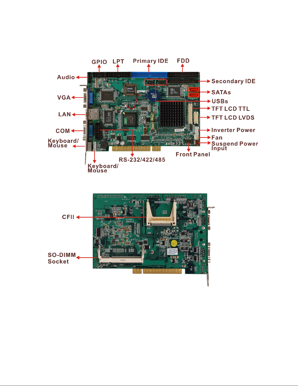
1.2 3307880 CPU Board Overview
3307880 PCI CPU Card
Figure 1-1: 3307880 CPU Board Overview (Front View)
Figure 1-2: 3307880 CPU Board Overview (Solder Side)
1.2.1 3307880 CPU Board Connectors
The 3307880 CPU board has the following connectors onboard:
1 x Audio connector
17

3307880 PCI CPU Card
1 x Battery connector
1 x CompactFlash® slot
1 x DDR SO-DIMM slot
1 x Fan connector
1 x Floppy disk drive connector
1 x Front panel connector
1 x GPIO connector
2 x IDE device connectors
1 x Inverter power connector
1 x Keyboard/Mouse connector
1 x Parallel port connector
1 x RS-232/422/485 serial port connector
2 x SATA connectors
1 x Suspend power input connector
1 x TFT LCD LVDS connector
1 x TFT LCD TTL connector
4 x USB 2.0 connectors
The 3307880 CPU board has the following connectors on the board rear panel:
1 x RJ-45 Ethernet connector
1 x Keyboard/Mouse connector
1 x Serial port connector
1 x VGA connector
The location of these connectors on the CPU card can be seen in Figure 3-1. These
connectors are fully described in Chapter 2.
NOTE:
There are no configuration jumpers or connectors on
the soldering side.
18

1.2.2 Technical Specifications:
3307880 CPU board technical specifications are listed in Table 1-1. Detailed descriptions
of each specification can be found in Chapter 2.
Specification 3307880
3307880 PCI CPU Card
CPU
Southbridge Chipset
Display
TTL/LVDS
Memory
BIOS
SSD
Super I/O
Audio
LAN
COM
AMD® Geode™ LX 800 500Mhz
AMD® Geode™ CS5536
CRT and 24-bit TTL integrated in AMD® Geode™ LX800
18-bit single channel LVDS
Supports one 1GB DDR 333/400 200-pin SO-DIMM SDRAM
module
Award BIOS
CompactFlash® (CF)
W83627EHG
AC'97 Codec Realtek ALC203
Realtek RTL8100C for 10/100 Mbps
One RS-232
One RS-232/422/485
USB2.0
IDE
Floppy
Parallel Port
SATA
KB/MS
Four USB 1.1 or USB 2.0 devices supported
Two IDE interfaces connect to four Ultra ATA33/66/100
devices
One floppy disk drive connector
One LPT port connector
Two SATA connectors with transfer rates up to 150MB/sec
One on-board keyboard/mouse connector
19
3307880 PCI CPU Card
Watchdog Timer
Digital I/O
Fan connector
Power Supply
Temperature
Humidity (operating)
Dimensions
Weight (GW)
Table 1-1: Technical Specifications
Software programmable 1-255 sec. by supper I/O
8 bit digital I/O, 4 input/4 output
One system fan connector
AT/ATX power support
0ºC - 60ºC
5%~95% non-condensing
165mm x 115mm
1.0Kg

3307880 PCI CPU Card
Chapter
2
2 Detailed Specifications
21

2.1 Overview
This chapter describes the specifications and on-board features of the 3307880 in detail.
2.2 CPU Support
The 3307880 CPU card comes with a preinstalled AMD® Geode™ LX 800 500MHz CPU.
2.2.1 AMD® Geode™ LX 800 500MHz Specifications
The specifications for the 500MHz AMD® Geode™ LX 800 are listed below
x86/x87-compatible core
Processor frequency up to 500 MHZ
64K I/64K D L1 cache and 128K L2 cache
3307880 PCI CPU Card
Split I/D cache/TLB (Translation Look-Aside Buffer)
64-bit DDR Memory interface up to 400MHz (LX 800), up to 333MHz (LX 700)
Integrated FPU that supports the Intel MMX® and AMD 3DNow!™
Technology instruction sets
9 GB/s internal GeodeLink™ Interface Unit (GLIU)
Security Block
o 128-bit AES (CBC/ECB)
o True Random Number Generator
High-resolution CRT and TFT outputs (simultaneous operation)
o Support for High Definition (HD) and Standard Definition (SD) standards
o Support 1920x1440 in CRT mode and 1600x1200 in TFT mode
VESA 1.1 and 2.0 VIP/VDA support
0.13 micron process
481-terminal PBGA (Plastic Ball Grid Array) with internal heatspreader
2.2.2 AMD® Geode™ LX 800 500MHz Power Management
The power management for the 500MHz AMD® Geode™ LX 800 is listed below:
1.8W Typical (3.9W TDP) @ 500MHz
GeodeLink active hardware power management
Hardware support for standard ACPI software power management
I/O companion SUSP#/SUSPA# power controls
22

Lower power I/O
Wakeup on SMI/INTR
2.3 System Chipset
The 3307880 CPU card has a preinstalled AMD® Geode™ CS5536 system chipset. The
system chipset features are listed below.
GeodeLink™ Interface Unit
o 64-bit, 66MHz operation
o PCI VSM (Virtual System Module) that makes the interface transparent to
applications software and BIOS
o Programmable routing descriptors, use and activity monitors, and SSMI
3307880 PCI CPU Card
(Synchronous System Management Interrupt)
ATA-6 Controller
o 100 MB/second IDE Controller in UDMA mode per the ATA-6
specification
o 5V interface
Flash Interface
o Multiplexed with IDE interface Connects to an array of industry standard
NAND Flash and/or NOR Flash
USB Controller
o 4 USB ports
o Supports both USB 1.1 and USB 2.0
o 3 host ports
o 1 host/device
Audio Codec 97 (AC97) Controller
o AC97 specification v2.3 compliant interface to multiple audio codecs:
Serial In, Serial Out, Sync Out, Bit Clock In
o Legacy “PC Beep” support
Diverse Device
o 82xx Legacy Devices
o IR Communication Port
o System Management Bus (SMB) Controller
o LPC (Low Pin Count) Port
o General Purpose I/Os (GPIOs)
23
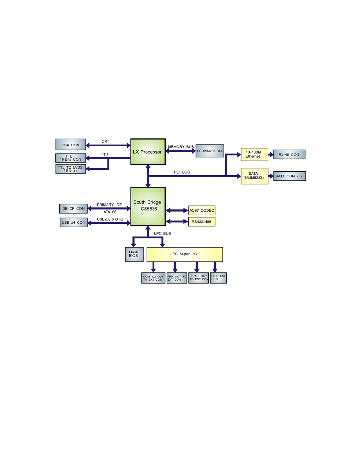
2.4 Data Flow
Figure 2-1 shows the data flow between the two on-board chipsets and other components
installed on the CPU card and described in the following sections of this chapter.
o 8 Multi-Function General Purpose Timers (MFGPTs)
o Real-Time Clock (RTC) with CMOS RAM
o Power Management Controller
o ACPI v2.0 compliant
Figure 2-1: Data Flow Block Diagram
2.5 Graphics Support
The Geode LX processor’s Graphics Processor is a BitBLT/vector engine that supports
pattern generation, source expansion, pattern/source transparency, 256 ternary raster
operations, alpha blenders to support alpha- BLTs, incorporated BLT FIFOs, a GeodeLink
interface and the ability to throttle BLTs according to video timing. New features added to
the Graphics Processor include:
Command buffer interface
Hardware accelerated rotation BLTs
24

3307880 PCI CPU Card
Color depth conversion
Paletized color
Full 8x8 color pattern buffer
Separate base addresses for all channels
Monochrome inversion
Table 2-1: Geode LX Graphics Features lists a complete list of Geode LX graphics
features. Fo
r more details, please refer to the AMD website or the Geode LX series data
book available from AMD.
Feature AMD Geode™ LX Processor
Color Depth 8, 16, 32 bpp (A) RGB 4 and 8-bit indexed
ROPs 256 (2-src, dest and pattern)
BLT Buffers FIFOs in Graphics Processor
BLT Splitting Managed by hardware
Video Synchronized BLT/Vector Throttle by VBLANK
Bresenham Lines Yes
Patterned (stippled) Lines Yes
Screen to Screen BLT Yes
Screen to Screen BLT with mono expansion Yes
Memory to Screen BLT Yes (throttled rep movs writes)
Accelerated Text No
Pattern Size (Mono) 8x8 pixels
Pattern Size (Color) 8x8 pixels
Monochrome Pattern Yes (with inversion)
Dithered Pattern (4 color) No
Color Pattern 8, 16, 32 bpp
Transparent Pattern Monochrome
Solid Fill Yes
Pattern Fill Yes
Transparent Source Monochrome
Color Key Source Transparency Y with mask
Variable Source Stride Yes
Variable Destination Stride Yes
Destination Write Bursting Yes
25

3307880 PCI CPU Card
Selectable BLT Direction Vertical and Horizontal
Alpha BLT
VGA Support Decodes VGA Register
Pipeline Depth Unlimited
Accelerated Rotation BLT 8, 16, 32 bpp
Color Depth Conversion 5:6:5, 1:5:5:5, 4:4:4:4, 8:8:8:8
Table 2-1: Geode LX Graphics Features
2.6 Memory Support
The 3307880 has one 200-pin DDR SO-DIMM SDRAM socket that supports one 333 MHz
or 400MHz DDR SO-DIMM memory module with a maximum capacity of 1GB.
2.7 PCI Bus Interface Support
The PCI bridge on the 3307880 has the following features:
33MHz Revision 2.2 is implemented
Yes (constant α, α/pix, or sep. α channel)
Maximum throughput: 133MB/sec
PCI and GLIU interface control
Read and write FIFOs
2.8 Ethernet Controller Specifications
2.8.1 Overview
The Realtek RTL8100C(L) is a highly integrated and cost-effective single-chip Fast
Ethernet controller. It is enhanced with an ACPI (Advanced Configuration Power Interface)
management function for PCI in order to provide efficient power management for
advanced operating systems with OSPM (Operating System Directed Power
Management).
The RTL8100C(L) also supports remote wake-up (including AMD Magic Packet™ and
Microsoft® Wake-up frame) to increase cost-efficiency in network maintenance and
manageme
nt. It is an ideal solution for notebook/CPU card-embedded network designs.
26

2.8.2 Features
3307880 PCI CPU Card
Integrates Fast Ethernet MAC, physical chip, and transceiver onto a single
chip
10Mbps and 100Mbps operation
Supports 10Mbps and 100Mbps N-way auto-negotiation
Supports 25MHz Crystal or 25MHz OSC as the internal clock source
Complies with PC99/PC2001 standards
Supports ACPI power management
Provides PCI bus master data transfer
Provides PCI memory space or I/O space mapped data transfer
Supports PCI clock speed of 16.75MHz-40MHz
Advanced power saving mode
Supports Wake-on-LAN and remote wake-up (AMD Magic Packet™, Link
Change, and Microsoft® Wake-up frame)
Half/Full duplex capability
Supports Full Duplex Flow Control (IEEE 802.3x)
Provides interface to 93C46 EEPROM to store resource configuration and ID
parameters
Provides PCI clock run pin
Provides LED pins for network operation status indication
2.5/3.3V power supply with 5V tolerant I/Os
2.9 Drive Interfaces
The 3307880 can support the following drive interfaces.
2 x SATA drives
2 x IDE devices
1 x FDD
1 x CF II card
2.9.1 SATA Drives
The 3307880 supports two, first generation SATA drives with transfer rates of up to
150MB/s.
27

2.9.2 IDE HDD Interfaces
The 3307880 system chipset IDE controller supports up to two HDDs with the following
specifications:
Supports PIO IDE transfers up to 16MB/s
Supports the following Ultra ATA devices:
o Ultra ATA/100, with data transfer rates up to 100MB/s
o Ultra ATA/66, with data transfer rates up to 66MB/s
o Ultra ATA/33, with data transfer rates up to 33MB/s
2.9.3 Floppy Disk Drive (FDD)
The 3307880 supports a single FDD. The following FDD formats are compatible with the
3307880 PCI CPU Card
board.
5.25”: 360KB and 1.2MB
3.5”: 720KB, 1.44MB and 2.88MB
2.9.4 Compact Flash Support
A standard CF II card can be inserted into the compact flash slot on the solder side of the 3307880
PCB.
2.10 Serial Ports
The 3307880 has two high-speed UART serial ports, configured as COM1 and
COM2/COM3. The serial ports have the following specifications.
16C550 UART with 16-byte FIFO buffer
115.2Kbps transmission rate
CN4 (COM2/COM3 serial port) can be configured as RS-232, RS-422 or RS-485.
2.11 Real Time Clock
256-byte battery backed CMOS RAM
28

2.12 System Monitoring
The 3307880 is capable of self-monitoring various aspects of its operating status
including:
CPU, chipset, and battery voltage, +3.3V, +5V, and +12V
RPM of cooling fans
CPU and board temperatures (by the corresponding embedded sensors)
2.13 USB Interfaces
The 3307880 has four internal USB interfaces (on two pin header connectors). The USB
interfaces support USB 2.0.
3307880 PCI CPU Card
2.14 BIOS
The 3307880 uses a licensed copy of AWARD BIOS. The features of the flash BIOS used
are listed below:
SMIBIOS (DMI) compliant
Console redirection function support
PXE (Pre-Boot Execution Environment) support
USB booting support
2.15 Operating Temperature and Temperature Control
The maximum and minimum operating temperatures for the 3307880 are listed below.
Minimum Operating Temperature: 0ºC (32°F)
Maximum Operating Temperature: 60°C (140°F)
A cooling fan and heat sink must be installed on the CPU. Thermal paste must be
smeared on the lower side of the heat sink before it is mounted on the CPU. Heat sinks
so mounted on the northbridge and southbridge chipsets to ensure the operating
are al
temperature of these chips remain low.
29

2.16 Audio Codec
The 3307880 has an integrated RealTek ALC203 codec. The RealTek ALC203 is a 20-bit
DAC and 18-bit ADC full-duplex AC'97 2.3 compatible stereo audio CODEC designed for
PC multimedia systems, including host/soft audio, and AMR/CNR based designs. The
codec meets performance requirements for audio on PC99/2001 systems
Single chip with high S/N ratio (>100 dB)
Meets performance requirements for audio on PC2001 systems
Meets Microsoft WHQL/WLP 2.0 audio requirements
20-bit DAC and 18-bit ADC resolution
18-bit Stereo full-duplex CODEC with independent and variable sampling rate
Complies with AC'97 2.3 specifications
3307880 PCI CPU Card
o LINE/HP-OUT, MIC-IN and LINE-IN sensing
o 14.318MHz -> 24.576MHz PLL saves crystal
o 12.288MHz BITCLK input can be consumed
o Integrated PCBEEP generator to save buzzer
o Interrupt capability
o Page registers and Analog Plug & Play
Support of S/PDIF out is fully compliant with AC'97 rev2.3 specifications
Three analog line-level stereo inputs with 5-bit volume control: LINE_IN, CD,
AUX
High quality differential CD input
Two analog line-level mono input: PCBEEP, PHONE-IN
Supports double sampling rate (96KHz) of DVD audio playback
Two software selectable MIC inputs
+6/12/20/30dB boost preamplifier for MIC input
Stereo output with 6-bit volume control
Mono output with 5-bit volume control
Headphone output with 50mW/20Ohm amplifier
3D Stereo Enhancement
Multiple CODEC extension capability
External Amplifier Power Down (EAPD) capability
Power management and enhanced power saving features
Stereo MIC record for AEC/BF application
DC Voltage volume control
30
 Loading...