

Global American 3307562 User Manual
3307562
3.5 inc h Embedded Motherboard
User ’s Manual
Edition 1.0
2005/2/16

3307562 User’s Manual
2
Copyright
Copyright 2004 - 2005. All rights reserved. This document is copyrighted and all rights are
reserved. The information in this document is subject to change without prior notice to
make improvements to the products.
This document contains proprietary information and protected by copyright. No part of this
document may be reproduced, copied, or translated in any form or any means without prior
written permission of the manufacturer.
A ll trademarks and/or registered trademarks contains in this document are property of their
respective owners.
Disclaimer
The company shall not be liable for any incidental or consequential damages resulting from
the performance or use of this product.
T he company does not issue a warranty of any kind, express or implied, including without
limitation implied warranties of merchantability or fitness for a particular purpose.
The company has the right to revise the manual or include changes in the specifications of
the product described within it at any time without notice and without obligation to notify any
person of such revision or changes.
Tradem ark
A ll trademarks are the property of their respective holders.
3307562 User’s Manual
3
Packing List
Please check the package bef or e you start ing setup the system
Hardware:
3307562 embedded minibo ar d x 1
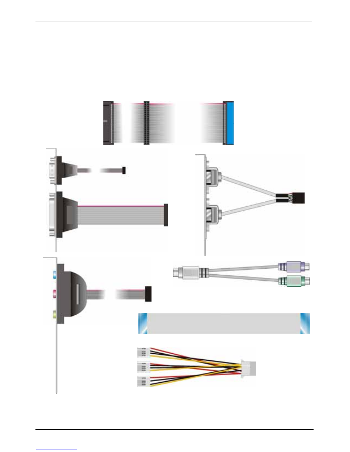
Cable Kit:
44-pin
44-pin
40-pin
44-pin ATA33 I DE Cable x 1
COM port & Printer Port Cable x 1
USB Cable x 1
Audio Cable x 1
Floppy Cabl e x 1
PS/2 keyboard & mouse cable x 1
CD Content :
Divers
User’s Manual
1 to 3 power
output cable

3307562 User’s Manual
4
Index
Chapter 1 < Intr oduct ion> ..............................................................................6
1.1 <Product Overview> ..........................................................................6
1.2 <Product Specification> .....................................................................7
1.3 <Mechanical Drawing> .......................................................................9
1.4 <Block Diagram>............................................................................. 10
Chapter 2 <Hardware Setup>....................................................................... 11
2.1 <Connector Location>...................................................................... 11
2.2 <Jumper Location & Reference>.......................................................12
2.3 <Connector Reference>................................................................... 13
2.3.1 <Internal Connector> ............................................................ 13
2.3. 2 < External Connector > ........................................................... 13
2.4 <CPU & Memory Set up>.................................................................. 14
2.4.1 <CPU>.................................................................................14
2.4.2 <Memory>............................................................................14
2.5 <CMOS Setup>............................................................................... 15
2.6 <Enhanced IDE & CF Interface> ....................................................... 16
2.7 < Floppy Port >..................................................................................17
2.8 <Ethernet Interface>........................................................................ 18
2.9 < O nboard Display Interface>............................................................19
2.10 < O nboard Audio Interface> ............................................................ 24
2.11 <Serial Port>................................................................................. 25
2.12 <GPIO Interface>........................................................................... 26
2.13 <Power Supp ly>............................................................................27
2.13.1 <Power output> .................................................................. 27
2.13.2 <Power Output>..................................................................27
2.14 <Switch and Indicator>................................................................... 28
Chapter 3 <BIOS Setup>.............................................................................. 29
Appendix A <I/O Pin Assignment>............................................................... 31
A.1 <IDE Port>......................................................................................31

3307562 User’s Manual
5
A.2 <Floppy Port > .................................................................................32
A.3 <IrDA Port>.....................................................................................32
A.4 < VGA Port >...................................................................................32
A.5 <Serial Port>...................................................................................33
A.6 <LAN Port> ..................................................................................... 33
A.7 <PS/2 Keyboar d & M ouse Port> ....................................................... 33
Appendix B <Flash BIOS>........................................................................... 35
B.1 BIOS Auto Flash Tool ................................................................ 35
B.2 Flash Method............................................................................35
Appendix C <System Resources>...............................................................37
C.1 <I/O Port Address Map> .................................................................. 37
C.2 <Memory Address Map>.................................................................. 38
C.3 <System IRQ & DMA Resources>....................................................39
C.3.1 <IRQ>.................................................................................39
C.3.2 <DMA>................................................................................ 39
Contact Information..................................................................................... 40

3307562 User’s Manual Introduction
Product Overview 6
Chapter 1 <Introduction>
1.1 <Product Overview>
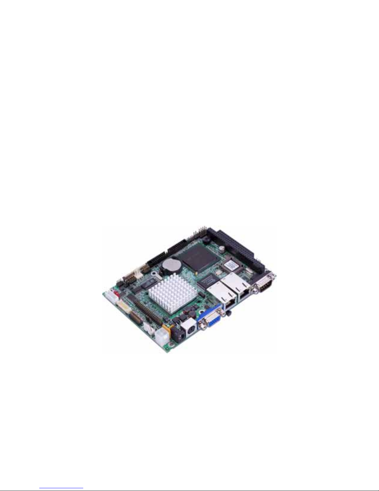
3307562 is the 3.5 inches embedded motherboard with AMD Geode GX1 platform, with
onboard VGA, AC97 audio, dual LAN and DC 12V input interface. Based on the AMD
Geode GX1 processor, the board provides many advanced features for reduced power
consumption, fanless design and high cost/price rate of production.
Low Power Consu mption
Based on the AMD Geode GX1@300MH z processor onboard, it only takes up to 3.7W at
maximum powering, and is completely suitable for fanless design. Without any cooling fan
onboard, it can avoid the heat problem when the cooler failed in accidence.
Onboar d TTL/LVDS LCD interf ace
Based on the AMD CS5530 of integrated graphics, the board provides onboard graphics
with up to 4MB of frame buffer, 18-bit LVDS and TTL interfaces.
Embedded Co mp onent
Due to the low profile design, the board provides PC/104 for ISA interface, CF card socket
for flash disk with porting embedded OS and up to 256MB of SO-DIMM.
Single Voltage Input
The board only requires DC 12V input; user’s can easily connect the board with an adapter
without the huge power supply.

3307562 User’s Manual Introduction
Product Specification 7
1.2 <Product Specification>
Gener al Specificat ion
Form Factor 3.5 inches embedded motherboard
CPU Embedded AMD Geode GX1 300MHz
Fanless with heatsink only
Memory 1 x 144-pin SO-DIMM up to 256MB
Unbufferred, none-ECC memory supported only
Chipset AMD Geode CS5530
BIOS Phoenix-Award PnP flash BIOS
Green Function Power saving mode includes doze, standby and suspend modes.
ACPI version 1.0 and APM version 1.2 compliant
Watchdog Timer System reset programmable watchdog timer
Real Time Clock Chipset built-in RTC with lithium battery
Enhanced IDE One Ultra DMA33 IDE interface supports up to 2 ATAPI devices
One 44-pin IDE port onboard
Multi-I/O Port
Chipset WINBOND W83977F-A
Serial Port One external RS232 & one internal RS232/422/485 serial ports
USB Port Two internal USB1.1 ports
Parallel Port One 26-pin internal parallel port
Floppy Port One slim type Floppy port
IrDA Port One IrDA compliant Infrared interface supports SIR
K/B & Mouse External PS/2 keyboard and mouse ports on rear I/O panel
GPIO One 12-pin Digital I/O connector with 8-bit programmable I/O
interface
Hardware
Monitor
Fan speed, CPU temperature and voltage monitoring
VGA Display Interface
Chipset AMD Geode GX1 built-in VGA controller with 2D engine
Memory BIOS selectable up to 4MB shard with system memory
Display Type CRT, LCD monitor with analog display
18-bit LV DS/TTL with LCD interface
Connector External DB15 female connector on rear I/O panel
Onboard 40-pin TTL connector
Onboard 20-pin LVDS connector
Onboard 5-pin backlight inverter connector
Solid State Disk Interface
Compact Flash 1 x Compact Flash Card Type I socket on solder side
DOM Onboard 44-pin IDE support DOM (Disk On Module)

3307562 User’s Manual Introduction
Product Specification 8
Ethernet Interface
Controller Dual PCI based REA LTEK 8100B controller
Type
10Base-T / 100Base-TX, auto-switching Fast Ethernet
Full duplex, IEEE802.3U compliant
Connector Two external RJ45 jack on I/O panel
Audio Interface
Controller REALTEK ALC201A AC97 codec
Output Interface Line-in, Line-out, CD-in, MIC-in
Connector Onboard 10-pin header
Expansion Interface
ISA Onboard PC/104 interface
Power and Environment
Power
requirement
DC 12V input
1 x DC jack on I/O panel
1 x Onboard 4-pin 12V DC connector
Input Voltage 11V ~ 13V
Input Current 12V/2A 24W (board only)
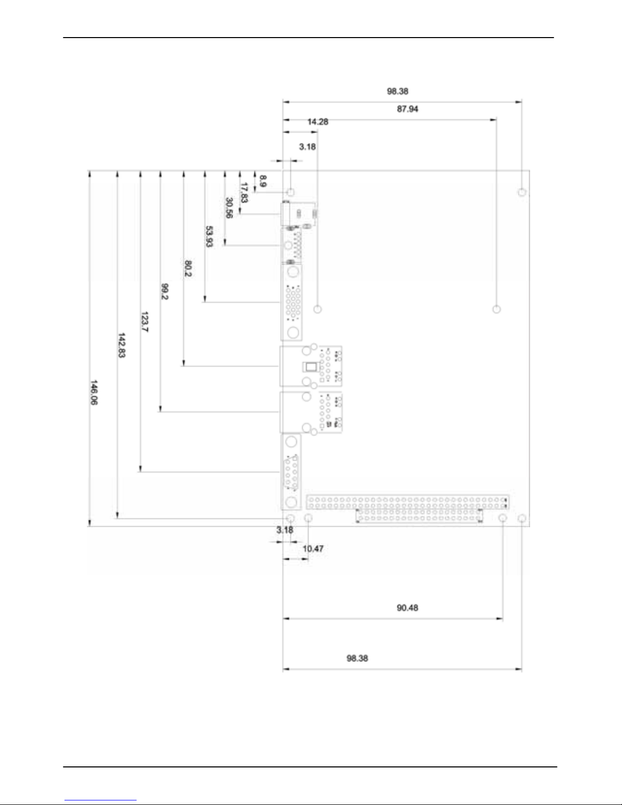
Dimension 146mm x 101mm (L x W)
Temperature
Operating within 0 ~ 60
o
C (32 ~ 140oF)
Storage within -20 ~ 85
o
C (-4 ~ 185oF)
Driver support
Windows Windows 98/SE/ME, NT4.0, 2000 and CE3.0
Linux Kernel version 2.4 or later
Ordering Code
3307562 3.5 inches embedded motherboard with onboard AMD GX1
300MHz processor, VGA, audio, dual LAN, USB, CF, TTL/LVDS
3307562 User’s Manual Introduction
Mechanical Drawing 9
1.3 < Mech anical Drawin g>

3307562 User’s Manual Introduction
Block Diagram 10
1.4 <B lock Di agram>
V
GA monitor
TTL/LVDS LCD
AM D Geode GX1 Processor
SO-DIM M up to 256MB
Dual LA N
PCI
ISA
PC/104
USB1.1
AC97 A udio
GPIO
BIOS
Floppy
Serial Port
Parallel Port
Ultra DM A33 IDE
IrDA
3307562 User’s Manual Hardware Setup
Connector Location 11
Chapter 2 <Hardware Setup>
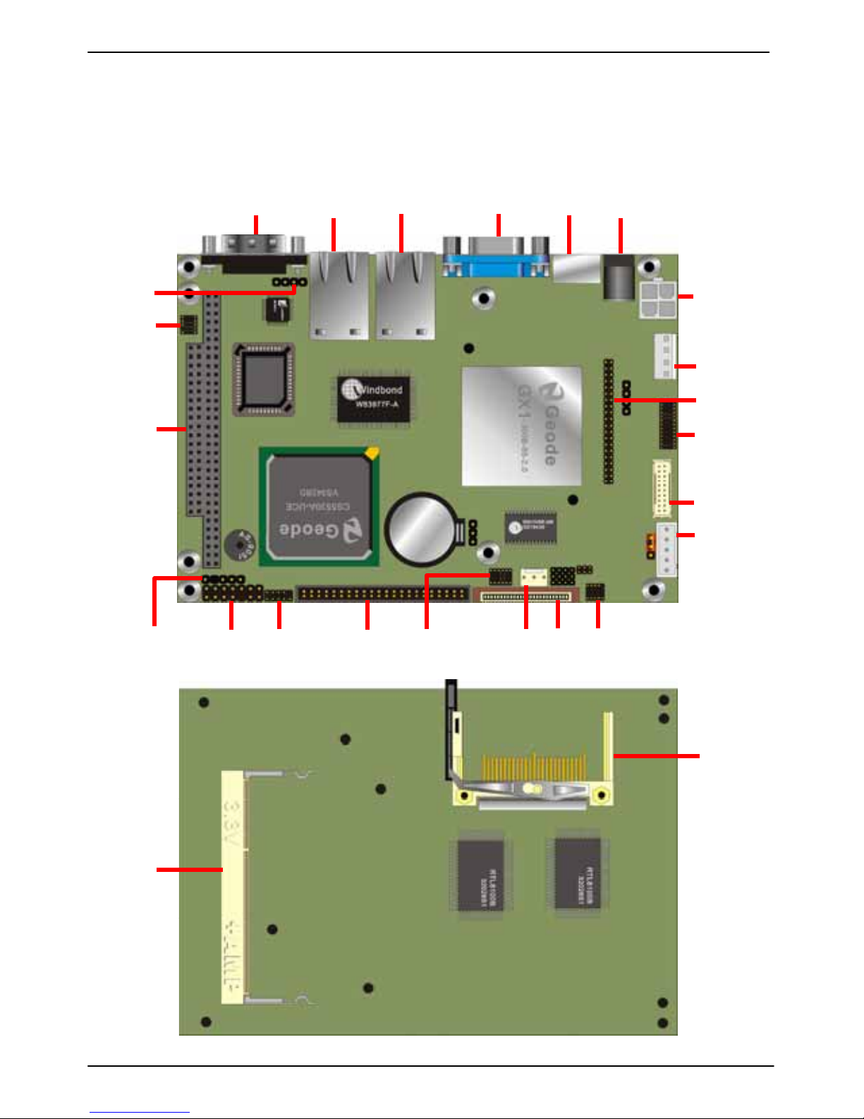
2.1 < Conn ect or Lo cat ion >
COM1 RJ45_2 RJ45_1 CRT PS2 DC_IN
CDIN
CN_AUDIO
PC104_A
CN_IR JFRNT CN_USB IDE1 CN_DIO SYSFAN FDD CN_COM2
CN_12V
CN_SPWR
CN_TTL
LPT
CN_LVDS
CN_INV
DIMM
CF
3307562 User’s Manual Hardware Setup
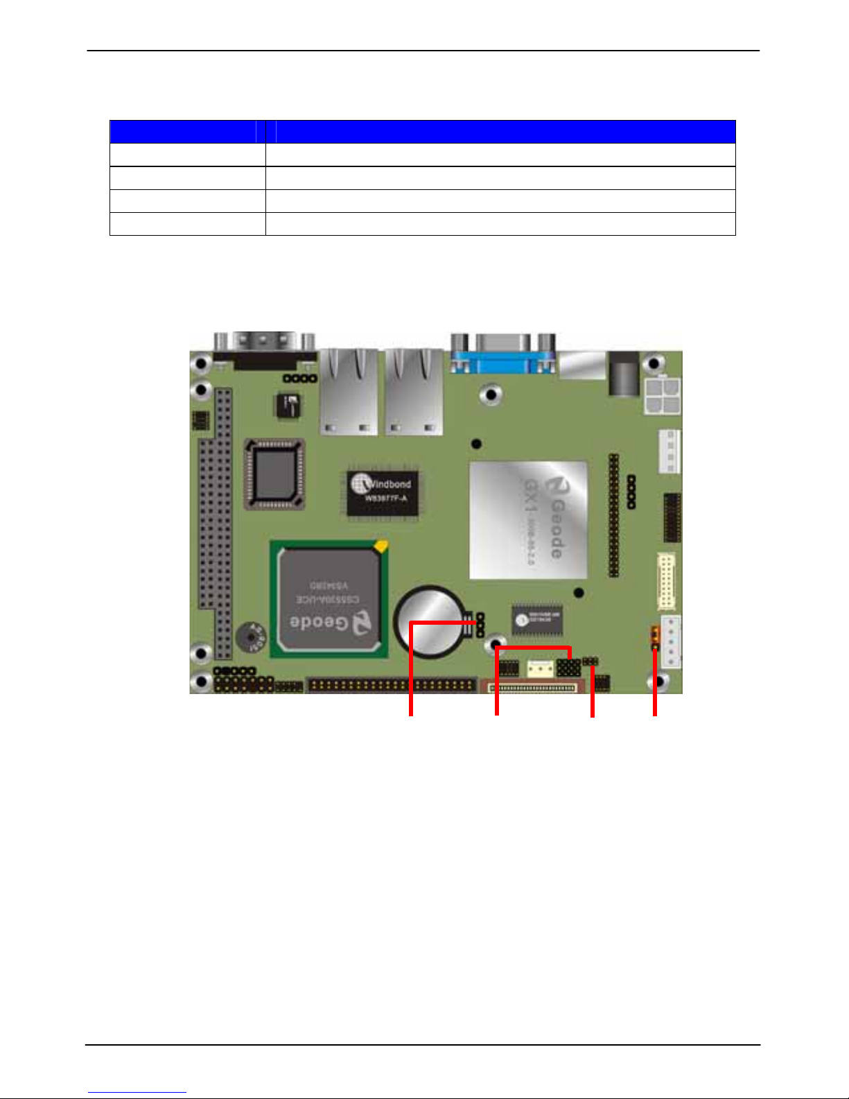
Jumper Location & Reference 12
2.2 <Jumper Location & Reference>
Jumper Function
JRTC RTC/CMOS Setting
JA TX A T/ATX Power Selection
JV OLT1 LCD Driving Voltage Setting
JCSEL1 / 2 COM2 RS-232/422/485 Mode Selection
JRTC JCSEL2 JCSEL1 JVOLT
 Loading...