

Global American 3304220 User Manual

330420 User’s Manual
Version 1.0
5.25" Embedded Controller with Socket 237 for Intel 486 Processor

Copyrights
This document is copyrighted and all rights are reserved. It does not allow any non
authorization in copied, photocopied, translated or reproduced to any electronic or
machine readable form in whole or in part without prior written consent from the
manufacturer.
In general, the manufacturer will not be liable for any direct, indirect, special, incidental
or consequential damages arising from the use of inability to use the product or
documentation, even if advised of the possibility of such damages. The manufacturer
keeps the rights in the subject to change the contents of this document without prior
notices in order to improve the function design, performance, quality and reliability. The
author assumes no responsibility for any errors or omissions, which may appear in this
document, nor does it make a commitment to update the information contained herein.
Trademarks
Intel is a registered trademark of Intel Corporation.
Award is a registered trademark of Award Software, Inc.
All other trademarks, products and or product's name mentioned herein are mentioned
for identification purposes only, and may be trademarks and/or registered trademarks of
their respective companies or owners.

CONTENTS
GENERAL INFORMATION..........................................................................................3
1.1 MAJOR FEATURES..................................................................................................4
1.2 SPECIFICATIONS.....................................................................................................5
1.3 DELIVERY PACKAGE ..............................................................................................6
HARDWARE INSTALLATION....................................................................................7
2.1 CAUTION OF STATIC ELECTRICITY....................................................................7
2.2 CAUTION ON UNPACKING AND BEFORE INSTALLATION................................8
2.3 3304220 LAYOUT ....................................................................................................9
2.4 QUICK LISTING OF JUMPERS...............................................................................10
2.5 QUICK LISTING OF CONNECTORS.......................................................................10
2.6 JUMPER SETTING DESCRIPTION........................................................................12
2.7 SETTING THE CPU OF 3304220..........................................................................13
2.8 CMOS DATA CLEAR............................................................................................14
2.9 CACHE SIZE SELECT ............................................................................................14
2.10 SYSTEM MEMORY DRAM................................................................................15
2.11 WATCH-DOG TIMER ..........................................................................................15
2.12 VGA CONTROLLER.............................................................................................17
2.13 DISKONCHIP? ADDRESS SETTING.................................................................18
CONNECTION...............................................................................................................19
3.1 THE FLOPPY DISK DRIVE CONNECTOR............................................................19
3.2 PCI E-IDE DRIVE CONNECTOR ...........................................................................20
3.3 PARALLEL PORT CONNECTOR...........................................................................21
3.4 SERIAL PORTS CONNECTORS..............................................................................22
3.5 KEYBOARD & MOUSE CONNECTOR..................................................................24
3.6 POWER'S LED, FAN AND KEY-LOCK CONNECTORS.......................................24
3.7 DC MAIN AND AUX. POWER CONNECTORS....................................................25
3.8 EXTERNAL FRONT PANEL CONNECTOR ..........................................................25
3.9 PS/2 MOUSE IRQ12 SELECTION CONNECTOR.................................................26
3.10 VGA CONNECTOR...............................................................................................26
3.11 FAST ETHERNET CONNECTOR.........................................................................27
3.12 PC/104 BUS CONNECTION .................................................................................27
3.13 FLAT-PANEL CONNECTOR................................................................................29
Connections for four standard LCDs................................................................30


3
Chapter-1
General Information
The 3304220 is an all-in-one half size industrial single board with design in Novell
NE2000 compatible 32-bit PCI bus Ethernet, provides 100 BASE-T or 10 BASE-T
for directly network automation demand.
Supports for various 40-133 MHz 80486SX/DX/DX2/DX4, 5x86 CPUs with
32-bit data bus and processing ability. Up to 64MB RAM by 72-pin SIMM
supported. Provides "DiskOnChip? " socket supported memory size up to 24 MB.
Design in with on board 1MB memory VGA architecture, supports direct interface to
color and monochrome Single Drive (SD) and Dual Drive (DD) STN, TFT & EL
panels and resolutions up to 1024x768 256 colors to CRT monitor.
The 3304220 support completed with all necessary I/O for industrial application. A
PCI enhanced IDE for two ATA-2 IDE drivers; supports up to two floppy disk
drivers; provide three high speed serial RS-232 ports and one RS232/422/485 port
with compatible to 16C550 UART with 16-byte FIFO; one enhanced bi-directional
parallel port which support SPP/EPP/ECP. The board also provides keyboard and
PS/2 mouse connector, PC/104 connector and one standard PCI slot etc.

4
1.1 Major Features
?? 80486SX/DX/DX2/DX4, 5x86 CPU supported.
?? ALi 1487/1489 chipset.
?? Supports DRAM up to 64 MB.
?? Fast PCI enhanced IDE controller supports two IDE drives.
?? Three high-speed serial RS-232 ports and one RS232/422/485 selectable port
(supports 16C550 UART with 16-byte FIFO).
?? One enhanced bi-directional parallel port supports SPP/EPP/ECP.
?? Keyboard and PS/2 Mouse connector.
?? On-board ALi M5113 Super I/O.
?? On-board 32 bit PCI-BUS VGA/ Panel controller.
?? "DiskOnChip™" Socket Supported Memory Size up to 24 MB.
?? On-board 32 bit PCI bus Ethernet, Novell NE2000 compatible.
?? Supports PC/104 connector.
?? One standard PCI slot.

5
1.2 Specifications
?? CPU: 80486SX/DX/DX2/DX4/5X86.
?? Bus interface: PCI bus
?? Chipset: ALi 1487/1489
?? Data bus: 32-bit
?? Processing ability: 32-bit
?? PCI Flat Panel / VGA Controller: VGA Chipset with 1 MB memory
interface to color and monochrome Single Drive (SS) and Dual Drive (DD)
STN, TFT & EL panels. Support CRT resolutions up to 1024x768 256
colors.
?? PCI Enhanced IDE interfaces: Supports up to two enhanced IDE
ATA-2).
?? RAM memory: Up to 64MB, uses two 72-pin SIMM sockets.
?? Cache memory: On board 128KB 2nd level cache.
?? Floppy disk drive interface: Supports up to two floppy disk drives.
?? Parallel port: One parallel port supports SPP/ECP/EPP.
?? Serial port: Three RS-232 ports one RS232/422/485 port supports
16C550 UART with 16-byte FIFO.
?? BIOS: AWARD flash BIOS.
?? Watchdog timer: Hardware circuit can be set by 1, 2, 10, 20, 110, or 220
seconds period Reset or NMI was generated when CPU did not periodically
trigger the timer.
?? Ethernet: Realtek RTL 8139, 32 bit PCI bus Ethernet, Novell NE2000
compatible.
?? Keyboard / Mouse connector: 8-pin connector supports standard
PC/AT keyboard and a PS/2 mouse.
?? PC/104: 104-pin connector support 16 bit ISA Bus.
?? PCI slot: Standard PCI bus expansion slot.
?? Flash memory Disk: Reserved socket for "DiskOnChip™", support up to
24MB Flash memory disk.

6
?? Power connector: Support 4-PIN power connector input (+5V, +12V).
?? CMOS: Real-time clock/calendar and battery backup by DS12B887 or
equivalent device.
?? Power supply voltage: +5V±5%, +12V±5%.
?? Max. Power requirement: +5V @2.2A.
?? Operating temperature: 0-55°C (CPU need cooler).
?? Board size: 8" (L) x 5.75" (W) (203mm x 146mm).
1.3 Delivery Package
The delivery package of 3304220 includes all following items:
?? 3304220 Industrial Single Board
?? Printer port Flat Cable
?? IDE port Flat Cable
?? FDD port Flat Cable
?? 40-pin COM ports Cable
?? Flat Panel Cable
?? Front Panel Cable
?? Ethernet Cable
?? PS/2 Mouse and Keyboard Transfer Cable
?? Utility Diskette
?? User’s Manual
Please contact with your dealer if any of these items are missing or damaged
when purchasing. And please keep all parts of the delivery package with
packing materials in case of you want to ship or store the product in feature.

7
Chapter-2
Hardware Installation
This chapter provides the information on how to install the hardware of
3304220. At first, please follow up sections 1.3, 2.1 and 2.2 in check the
delivery package and carefully unpacking. Following after, the jumpers setting
of switch, watchdog timer, and the DiskOnChip? address selection.
2.1 Caution of Static Electricity
The 3304220 has been well package with a anti-static bag in protect its
sensitive computer components and circuitry from the damage of static
electric discharge.
Note: DO NOT TOUCH THE BOARD OR ANY OTHER SENSITIVE
COMPONENTS WITHOUT ALL NECESSARY ANTI-STATIC
PROTECTION.
You should follow the steps as following to protect the board in against the
static electric discharge whenever you handle the board:
1. Please use a grounding wrist strap on whoever needs to handle the
3304220. Well clip the ALLIGATOR clip of the strap to the end of the
shielded wire lead from a grounded object. Please put on and connect the
strap before handle the 3304220 for harmlessly discharge any static
electricity through the strap.
2. Please use anti-static pad for put any components or parts or tools on the
pad whenever you work on them outside the computer. You may also in
use the anti-static bag instead the pad. Please ask from your local supplier in
help up your necessary parts on anti-static requirement.

8
2.2 Caution on Unpacking and Before Installation
First of all, please follow with all necessary steps of section 2.1 in protection
the 3304220 from electricity discharge. With refer to section 1.3, please check
the delivery package again with following steps:
1. Unpacking the 3304220, keep well storage of all packing material, manual
and diskette etc. if has.
2. Is there any components lose or drop from the board? DO NOT
INSTALL IF HAPPENED.
3. Is there any visual damaged of the board? DO NOT INSTALL IF
HAPPENED.
4. Well check from your optional parts (i.e. CPU, SRAM, DRAM, ROM-Disk
etc.) for completed setting all necessary jumpers setting to jumper pin-set
and CMOS setup correctly. Please also reference to all information of
jumpers setting in this manual.
5. Well check from your external devices (i.e. Add-On-Card, Driver Type etc.)
for completed add-in or connection and CMOS setup correctly. Please also
reference to all information of connector connection in this manual.
6. Please keep all necessary manual and diskette in a good condition for your
necessary re-installation if you change your Operating System or whatever
needs.
9
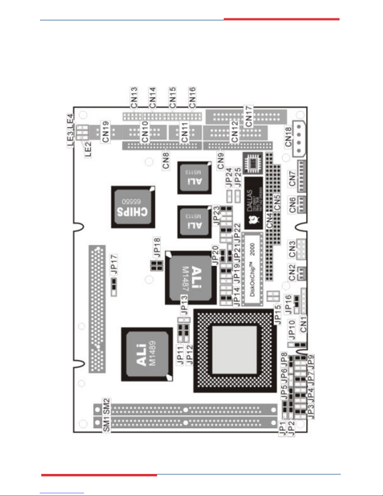
2.3 3304220 Layout

10
2.4 Quick Listing of Jumpers
JP1, 2, 3, 4, 5, 7, 8, 9, 10 — for CPU type setting
JP6 — for AMD CPU type selection
JP11, 12 — for Cache size setting
JP13 — CPU clock selection
JP14 — for DiskOnChip™ address setting
JP15 — CPU's Vcore voltage level selection setting
JP16 — CPU's operating voltage selection setting
JP17 — PCI clock setting
JP18 — CPU Clock-in selection
JP19 — WATCH-DOG Time-out period selection
JP20 — PS/2 Mouse IRQ selection
JP21 — WATCH-DOG Active selection
JP22 — RS422/485 Receiver Enable Control
JP23 — RS422/485 Transceiver Enable Control
JP24 — COM4 Enable/Disable setting
2.5 Quick Listing of Connectors
CN1: POWER LED/KEYLOCK
CN2: FAN CON
CN3: FRONT PANEL
CN4: PC104-64
CN5: PC104-40
CN6: POWER CONNECTOR (-12V, -5V)
CN7: KEYBOARD + MOUSE CONNECTOR
CN8: FLAT PANEL PORT
CN9: HDD (IDE) CONNECTOR
CN10: VGA CONNECTOR
CN11: RS422/RS485
CN12: PARALLEL PORT
 Loading...