

Global American 3302012 User Manual

3302012
Single Board Computer
User’s Manua l
Edition 1.1
2004/3/26
1

Copyright
Copyright© 2003 - 2004. All rights reserved. This document is copyrighted and all rights are
reserved. The information in this docum ent is subject to change without prior notice t o ma ke
improvements to the products.
This document contains proprietary information and protected by copyright. No part of this
document m ay be reproduced, copied, or translated in any form or any means wit hout prior
written permission of the manufacturer.
All trademarks and/or registered trademarks contains in this docum ent are property of their
respective owners.
Disclaimer
The com pany shall not be liable for any incidental or cons equential damages resulting from
the performance or use of this product.
The com pany does not issue a warranty of any kind, express or impli ed, including wi thout
limitation implied warranties of m erchantability or fitness for a particular purpose.
The company has the right to revise the manual or include ch anges i n t he specifications of
the product described within it at any time without notice and without obligation to notify any
person of such revision or changes.
Tradema rk
All trademarks are t he property of their respective holders.
Any qu estions please visit our website at http://www.globalamericani nc.com
2
Packing List
Hardware
3302012 Motherboard......................................................... X 1
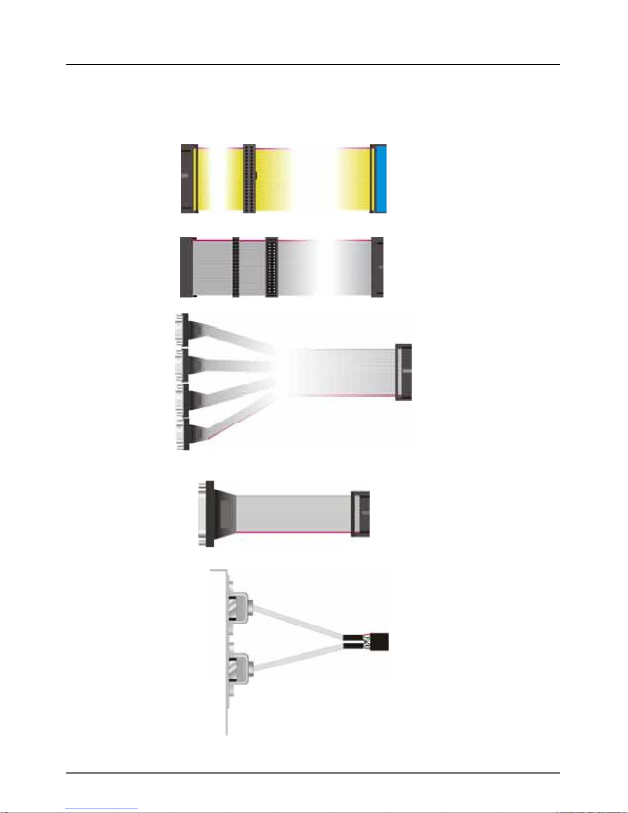
Cable Kit
UltraATA/100 IDE cable........... ................. .............. .......... X 1
Floppy cable ............................................. ................. ....... X 1
Quad COM ports DB9 male cabl e .... ........ .... ........ ............ X 1
Parallel Port DB25 female cable ..................................... .. X 2
Dual USB ports cable ..................................... ....... ........... X 1
3
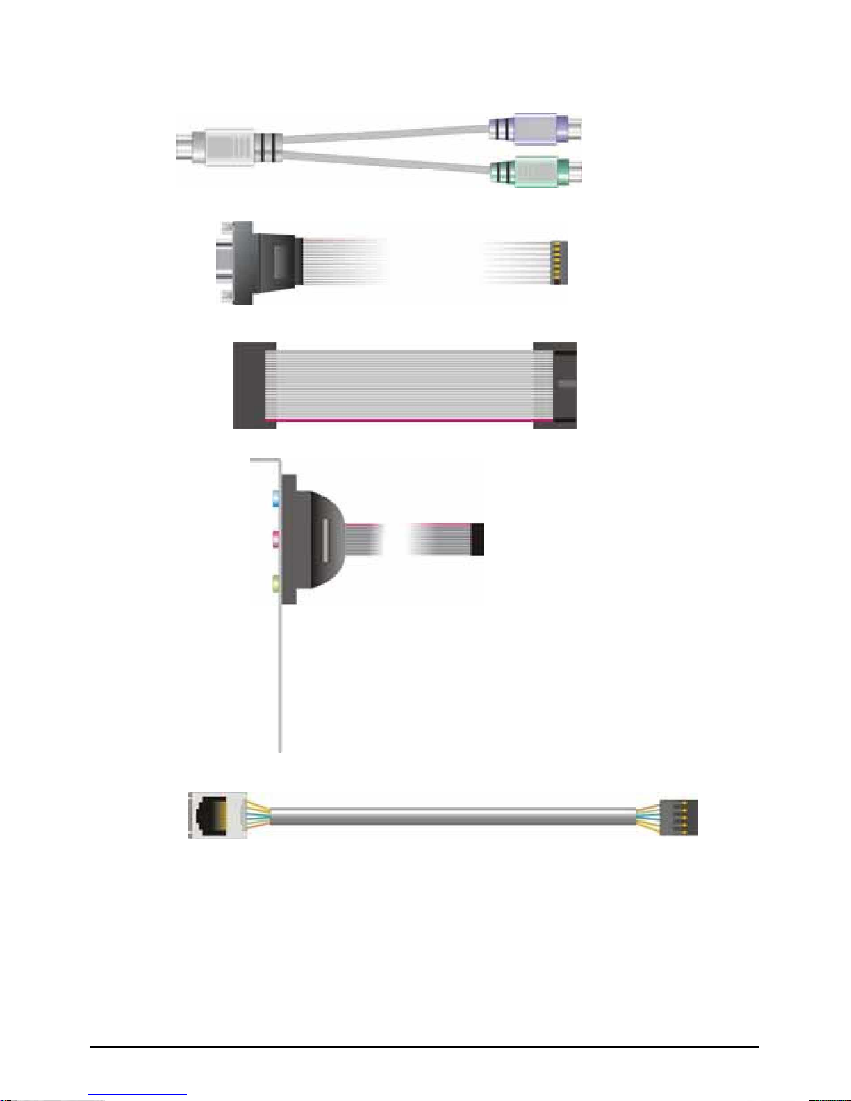
PS/2 Keyboard and mouse cable .... ....... ....... ....... ........ .... X 1
VGA DB15 female cable ................................................... X 1
20-pin 16-bit GPIO cable .................................................. X 1
Audio cable .............................. ............ ............ ............ ..... X 1
RJ45 LAN port cable.................. ........................ ............ ... X 1
AV and S-Video TV-out cable (3302012A only) .............. X 1
Printed Matter and Softw are
User’s manual.......................................................... ......... X 1
Driver CD .......................................................................... X 1
4

Index
Chapter 1 < Introduction >
..........................
.......................................................................... 7
1.1 Product Overvi ew
..........................
........................................................................ 7
1.2 < Product Specification > ........................... .......................................... .................8
1.3 < Component Placement > ................. .............. ........................................ .......... 11
1.4 < Block Diagram > ............... ...............................................................................12
Chapter 2 < Hardware Setup >................................................... ........................................13
2.1 < Connector Location >.......................................................................................13
2.2 < Jumper Location & Reference > .................. .............................. ......................14
2.3 < Connector Reference >....................................................................................15
2.4 < CPU and DRAM setting > ........................................................................... .....16
2.5 < CMOS Setting > ........... ......................................................... ...........................16
2.6 < Watchdog Timer Setting >.................. ......................................................... .....17
2.7 < Embedded Flash Disk >........................................................ ...........................18
2.6 < Power & Fan Connector >.......................................... ................................. .....19
2.7 < Display Interfaces > ..................... ................................................... .................20
2.71 Standard Analog VGA Interface ...................... ...................... ...................20
2.7.2 Digital VGA Interface ....................................... .......................................21
2.73 < TV-out Interface > ........................................... ..................................... .25
2.8 < Ethernet Interface > ............................. ............................................................26
2.9 < Audio Interface > ................................................ .................................... ..........27
2.10 < Multi I/O Port > ...... .................................. ............................................. ..........28
2.10.1 < Serial Ports >.....................................................................................28
2.10.2 < GPIO Interface > ................................. .............................................. 29
2.11 < Expansive Bus Interface > ........................ ................................................ .....30
2.11.1 < PCI bus interface > ....... .................................. ............................ .......30
2.11.2 < PC/104+ Interface > .................... ......................................................31
2.12 < Switch and Indicator > .................. ............................................................ .....32

5

Chapter 3 < BIOS Setup >........................ ..........................................................................33
Chapter 4 < Driver Installation > .............................. ................................. ..........................35
Appendix A < I/O Ports Pin Assignment >..................... ............................ ........................ ..36
A.1 < IDE port > ........... ................................................................................... ..........36
A.2 < Floppy Port > ........ ................................................................................. ..........38
A.3 < Parallel Port >..................................................................................................39
A.4 < Serial Port >.....................................................................................................40
A.5 < USB Port > .................................. ....................................................................41
A.6 < IrDA Port >.......................................................................................................41
A.7 < PS/2 Keyboard and Mouse Port > ... .............. ....................... ................. ..........41
Appendix B < BIOS Flash Information >.......... ...................................................................43
B.1 < BIOS Flash Tool > ............................................. ..............................................43
B.2 < Flash Method >................................................................................................43
Appendix C < System Resource > ......................................... ............................................45
C.1 I/O Port Address Map .................. .................................... ...................................45
C.2 < Memory Address Map > ..................................... ........................................ .....46
C.3 < IRQ and DMA Resource >.......................... ........................................... ..........47
Contact Information ............................................................................................................49
6

3302012 User’s Manual
Chapter 1 < Introduction >
Introduction
1.1 Product Overview
The 3302012 SBC (Single Board Computer) is an all-in-one industrial 5.25” drive-size
EBX-compliant motherboard computer based on Intel socket 370 architecture, supports
Intel Tualatin/Coppermine FC-PGA2, FC-PGA Pentium-III / Celeron and VIA C3 Samuel I/II,
Ezra CPU up to 1.4 GHz at 66, 100, 133 MHz of FSB with PC100/133 SDRAM. Based on
value VIA/S3 Twister-T PN133T chipset with VIA 8606T north-bridge and 686B
south-bridge, the 3302012 supports the Intel and VIA latest socket 370 based CPU, 51 2 MB
PC133 SDRAM and VIA/S3 Savage4 3D SVGA core with BIOS selectable 8/16/32 MB
video m emory shard with system memory.
To be the requirement of multi-media computing platform, the 3302012 also off ers the
LVDS/TTL TFT/DSTN LCD interface and optional AV and S-video TV-out at NTSC/PAL
mode. The onboard Fast Ethernet, PC/104 and PC/104-plus, 4 COM / 2 LPT ports, 2 USB
ports and 16-bit GPIO port also provides the interfaces for embedded peripherals for the
POS/POI, Kiosk, ATM, and Panel PC, industrial workstation, node terminal, transaction
station and industrial embedded application.
With these features, 3302012 should be the value, powerful and all-in-one integration
solution incl uding, but not limited to the following.
Value Advanced Computing Platform
Intel latest Tualatin Pentium-III / Cel eron an d VIA C3 CPU up to 1.4 GHz with 133 MHz
FSB, 512 MB PC133 SDRAM of system memory for high- end industrial com puting platform
with high CPU and memory loading.
LVDS/TTL TFT/DSTN LCD Interface
VIA/S3 Twister-T integrated S3 Savage4 3D SVGA core, BIOS selectable 8/16/32 MB
of video m emory shared with system memory, and 2 x 18-bit LVDS / TTL TFT/DSTN LCD
interface offers the value and performance solution for the LCD-based multi-media
applications.
Multiple I/O Port and Solid St ate Disk Interface
Onboard 4 COM, 2 parallel, 2 USB and 16-bit GPIO ports offer the interface for
industrial embedded peripherals and application. The DiskOnChip socket and IDE-based
DiskOnModule (DOM) interface provides the SSD (Solid State Disk) wit h flash disk for disk
free and embedded OS based application.
7
3302012 User’s Manual
1.2 < Product Specification >
General Specification
Introduction
Form Factor 5.25” drive-size EBX compli ant single board computer
CPU Socket 370 Intel Pentium-III / Celeron, VIA C3 CPU
Up to 1.4 GHz at 66/100/133 MHz of FSB
Intel Tualatin / Coppermine FC- PGA2 / FC-PGA CPU an d VIA C3
Samuel I/II, Ezra CPU
Chipset VIA Twister-T PN133T with 8606T and 686B
DRAM One 168-pin DIMM socket supports up to 512MB PC100/133
SDRAM
BIOS Phoenix-Award 2Mb PnP flash BIOS
Enhanced IDE PCI enhanced IDE interface support s dual ports up to 4 ATAPI
devices with UltraATA/ 100 supported
One 40-pin IDE1 and one 44-pin I DE2 box header
Green Function Power saving mode supported in BIOS with DOZE, STANDBY
and SUSPEND modes. ACPI version 1.0 and APM version 1.2
compliant
Watchdog Timer 6-level generates NMI or system reset programmable watchdog
timer
Real Time Clock VIA 686B built-in RTC with onboard lithium battery
Multi-I/O Port
Chipset VIA 686B built-in super I/O controller
Winbond W 83977EF-AW for COM3/4 and LP T2 Ports
Serial Port Three RS-232 seri al port COM1/3/4 and one jumper selectable
RS-232/422/485 serial port CO M2.
Both with 16C550 compatible UART and 16 bytes FI FO
Parallel Port Two bi-direction par allel port with SPP/ECP/EPP mode
USB Port Two USB ports with USB version 1.1 compliant
GPIO Port One 16-bit programmable general purpose I/O port
Floppy Port One floppy port supports up to two FDD
IrDA Port One IrDA compliant I nfrared interface supports SIR
K/B & Mouse PS/2 keyb oard and m ouse port
Expansive Interface
PCI Bus One 32-bit/33 MHz PCI slot with 3 x bus master PCI via an
additional riser card
PC/104-plus One 120-pin 32-bit PCI-based PC/104-plus interface
One 104-pin 8-/16-bit ISA-based PC/ 104 interface
8

3302012 User’s Manual
Solid State Disk Interface
Introduction
Flash Type M-systems DiskOnChip2000 Millennium flash disk
Package Single chip flash disk in 32-pin DIP JEDEC
Capacity 8M to 1GBytes of flash m emory f or DiskOnChip
Data Reliability ECC / EDC data protection
Memory Window 8 KBytes of memory window
Display Interface
Chipset VIA/S3 T
isterw
-T PN133T chipset built-in S3 Savage4 SVGA
controller with 128-bit 3D/2D engine
Video Memory BIOS selectable 8/16/32MBytes of video memory shared with
system m emory
Display Type CRT and LCD monitor
LVDS/TTL TFT/DSTN Color LCD
Display M ode VGA, SVGA, XGA, SXGA, UXGA
Up to 1920 x 1440 of resolution for CRT monitor
LCD Interface 36-bit TFT/DSTN LCD interface with 256 gray shade
Integrated 2-channel 110 MHz LVDS interface
Support up to 1280 x 1024 of resolution
Connector Onboard 16-pin header connector for CRT
Onboard 50-pin header connector for TTL LCD
Onboard 2 x 20-pin Hirose DF13-20DP-1.25V for LVDS
Ethernet Interface
Chipset PCI RTL8100B Fast Ethernet controller
Type 10Base-T / 100Base-TX, auto-switching Fast Ethernet, full
duplex, IEEE802.3U compliant
Connector Onboard 10-pin header connector
Audio In eterfac
Chipset VIA 686B built-in AC97 3D audio controller with codec
Interface Lin e-in, l ine-out, MIC-in and CD-in
Connector Onboard 10-pin header for line-in, line-out and MIC-in
Onboard 4-pin header for CD-in
9
3302012 User’s Manual
Power and Environment
Introduction
Power Req. +5V, +12V DC input
+5V @ 4.2A t ypically with I ntel Socket 370 FC-PGA Pentium-III
866 MHz CPU and 128 MB PC133 SDRAM
ATX Function One 3-pin ATX interface wit h 5V standby
Dimension 146 x 203 mm or 5.75” x 8” (L x W ), standard EBX size
Weight 0.30 Kg (Board only)
Temperature Operating within 0 ~ 60oC (32 ~ 140oF)
Storage within -20 ~ 85oC (-4 ~ 185oF)
Ordering Code
3302012B 5.25" Drive-size Socket 370 Tualatin EBX single board computer
with LVDS/TTL TFT/DSTN LCD / CRT SVGA, Audio, LAN,
PC/104-plus and 4 COM, 2 LPT 16-bit GPIO and Disk,
Socket
OnChip
3302012A 5.25" Drive-size Socket 370 Tualatin EBX single board computer
with CRT SVGA, AV & S- Video TV-out, Audio, LAN, PC/104-plu s
and 4 COM, 2 LPT, 16-bit GPIO and DiskOnChip Socket
OEM Version Other Configuration based on 3302012 with Optional / Removable
Interface
10
3302012 User’s Manual
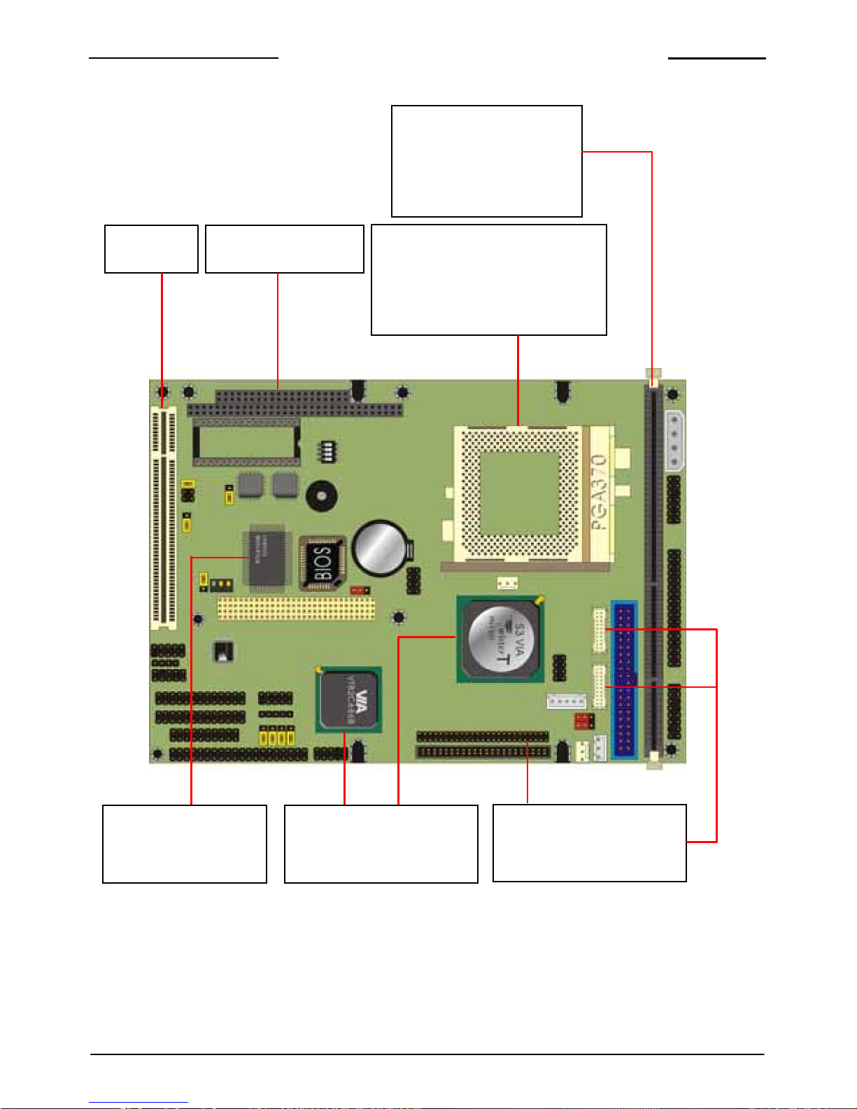
1.3 < Component Placement >
Introduction
1 X 168-pin DIMM
Supports up to 512MB
PC133 SDRAM
PCI Slot PC/104 & PC/104+
FC-PGA/FC-PGA2 socket 370
for Intel Pentium III /Celeron
or VIA C3 processor
Realtek RTL8100B
10/100Mbps LAN
VIA Twister-T PN133T
& 686B chipset
LVDS/TTL TFT/DSTN
LCD interface
11
3302012 User’s Manual
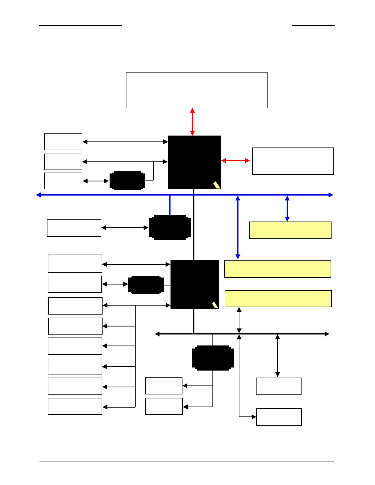
1.4 < Block Diagram >
Introduction
Intel Socket 370 Tualatin/Coppermine
FC-PGA2/FC-PGA Pentium-III / Celeron
VIA Socket 370 C3 Samuel I/II, Ezra CPU
FSB 66/100/133 MHz
CRT
LCD
TV
LVDS/TTL
Encoder
S3-VIA
PN133T
N/B
PC133
1 x 168-pin DIMM Socket
512 MB PC133 SDRAM
PCI Bus Interface
LAN
10/100 M bps
RTL8100B
LAN
PCI Add- on Cards
ATA PI Device
Audio Devices
USB Devices
ATA100 IDE
Codec
VIA
686B
S/B
PC/104-plus Add-on Modules
PC/104 Add-on Modules
PS/2 Keyboard
ISA Bus Interface
PS/2 M ouse
FDD
Winbond
SI/O
Serial Device
COM3 / 4
DiskOnChip
Parallel Device LPT2
16-bit GPIO
12

3302012 User’s Manual
Chapter 2 < Hardware Setup >
Hardware Setup
This chapter contains the information for the installation of hardware. The install
procedure includes jumper settings, CPU and memory installation, fan, I/O and panel
connections.
2.1 < Connector Location >
PCI1 DOC PC104AB PC104CD JPCIX CPUFAN
PWR
CN_ VT
PC104+
LAN
CDIN
JAUD
IO
JLPT2
JLPT1
JFRNT
CPU
JLVDS2
FDD
DIMM1
IDE1
VDS1JL
JVGA
JPS
JDIO JCOM SIR JUSB1 JPS2 JLCD IDE2 JBKL SYSFAN
13
3302012 User’s Manual
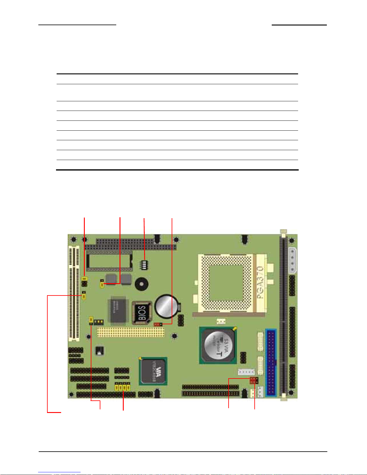
2.2 < Jumper Location & Reference >
Hardware Setup
Jumper Function
JRT
CMOSC
Setting
JWDT Watchdog Timer Mode Setting
SWDT Time Out Value of Watchdog Timer Setting
JDOC DiskOnChip Address Setting
JVOLT1 Flat Panel’s Voltage Setting
JVOLT2 Flat Panel’s Power Setting
JLAN LAN Enable/Disable Setting
JCSEL1 COM2 RS-232/422/485 Mode Setting
JCSEL2 COM2 RS-232/422/485 Mode Setting
JCS LE 2 JD CO SW TD JR CT
JWDT JLAN J SC EL1 JVOLT2 JVOLT1
14

3302012 User’s Manual
2.3 < Co nnector Reference >
Hardware Setup
Connect
tio
or Func
n Remark
CPU CPU Socket PGA370 Standard
DIMM1 168-pin DIMM Socket Standard
IDE1 40-pin Primary IDE Port Standard
IDE2 44-pin Secondary I DE Port Standard
FDD 34-pi n Floppy Port Standard
LPT1 26-pin Primary Parallel Port Standard
LPT2 26-pin Secondary Parallel Port Standard
JUSB1 10-pin 1st / 2nd USB Port Standard
JCOM 40-pin COM1/2/3/4 RS232 Serial Port Standard
JDIO 20-pin 16-bit GPIO Port Standard
DOC 32-pin DiskOnChip Socket Standard
JPS2 10-pin PS/2 Keyboard / Mouse Connector Standard
SIR 5-pin SIR IrDA Port Standard
PWR 4-pin AT Power Connector Standard
JPS 3-pin ATX Signal Connector Standard
JFRNT 14-pin Front Panel Connector Standard
CPUFAN 3-pin CPU Fan Connector Standard
SYSFAN 3-pin System Fan Connector Standard
JVGA 16-pin Internal VGA Port Standard
JAUDIO 10-pin Audio Port Standard
CDIN 4-pin CD-in Interface Standard
LAN 10-pin LAN Port Connector Standard
JBKL 5-pin Backlight Inverter power connector B Only
JLCD 50-pin TTL LCD Interface B Only
JLVDS1, JLVDS2 20-pin LVDS LCD Interface B Only
CN_TV TV-out Interface A Only
PCI1 32-bit PCI Slot Standard
JPCIX 10-pin PCI Expansive Signal Header Standard
PC104AB/CD 104-pin PC/104 Connector Standard
PC104P 120-pin PC/104-plus Connector Standard
15
3302012 User’s Manual
2.4 < CPU and DRAM setting >
Hardware Setup
The board is based on Intel socket 370 Pentium-III / Celer on architecture supports Intel
FC-PGA and VIA C3 CPUs at 66/100/133 MHz of FSB. The FSB, ratio and voltage of CPU
is default set by CPU without any additional jumper selection. The CPU shoul d be install ed
into the CPU ZIF soc ek t.
The board supports PC100/133 SDRAM up to 512 Mbytes of memory capacity on one
168-pin DIMM os cket DIMM1.
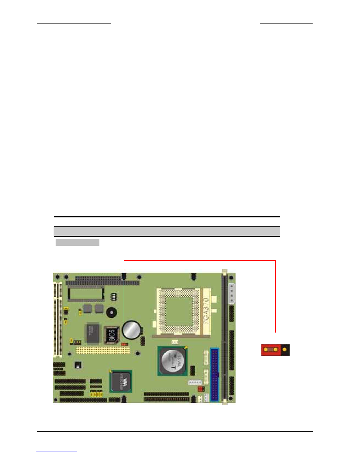
2.5 < CMOS S te ting >
The board’s data of CMOS can be setting in BIOS. If the board refuses to boot due to
inappropriate CMOS se ttin gs, he re is how to pro ceed to clear (reset) the CMOS to its
default values.
Jumper: JRTC
Type: onboard 3-pin header
JRTC
1-2
Mode
Clear CMOS
2-3 Normal Operation
Default setting
JRTC
3 1
16
 Loading...