

Global American 3301040 User Manual

User’s Manual
3301040

Wa
rning
Single Board Computers and their components contain very delicate Integrated Circuits (IC). To protect the Single Board Computer and its components against
damage from static electricity, you should always follow the following precau- tions when handling it :
1. Disconnect your Single Board Computer f rom th e power s ource when you want to work on the inside
2. Hold the board by the edges and try not t o touch the IC chips, leads or ci rcuitry
3. Use a grounded wrist strap when handling computer components.
4. Place components on a grounded antistatic pad or on the bag th at came with the
Single Board C omputer, whenever components are separated from the system
Replacing the lithium battery
Incorrect replacement of the lithium battery may lead to a risk of explos ion.
The lithium battery must be replaced with an identical b attery or a battery type rec om- mended by the manufacturer (BR2335).
Do not throw lithium batteries into the trashcan. It must be disposed of in accordance with local regulations concerning special waste.
3301040 User's Manu al
2

Table of Contents
Replacing the lithium battery ....................................................... 2
Technical Support ......................................................................... 2
Specifications ................................................................................ 5
Packing list .................................................................................... 6
Board Image (boxheader version)...............................................8
Board Layout (Front) .................................................................... 8
Board Layout (Back) ..................................................................... 9
Board Dimension .......................................................................... 9
Connector Quick Reference ...................................................... 10
Jumper Quick Reference ........................................................... 10
CMOS Jumper Settings .............................................................. 11
Watchdog Output ........................................................................ 11
Wake On LAN .............................................................................. 11
Serial Port Selection (RS 232C/422/485).................................... 12
COM1~COM4 Power Source Special Support ......................... 12
LVDS Voltage Selection .............................................................. 14
Audio Interface ............................................................................ 14
CDIN Connector .......................................................................... 14
VGA Connector ............................................................................ 15
LAN LED ...................................................................................... 15
CFD Master/Slave Selection ....................................................... 15
CPU Fan Connector .................................................................... 16
System Fan Connector ............................................................... 16
TV-out Connector ........................................................................ 16
18bit/24bit TTL Flat Panel Connector........................................ 17
INV Connector ............................................................................. 17
36bit Panel Connector ................................................................ 18
18/24bit LV DS LCD Connector ................................................... 18
USB1 Connector (box header version only) ............................. 19
USB2 Connector (connector version only) .............................. 19
Interface Connectors FDD .......................................................... 20
Fast Ethernet Connectors .......................................................... 21
LPT1 ............................................................................................. 21
Keyboard & PS/2 Mouse ............................................................ 22
4P Power Connector................................................................... 22
IrDA Connector ........................................................................... 22
3301040 User's Manu al
3

Switches and Indicators............................................................. 23
LED Indicator............................................................................... 24
A TX Feature Connector .............................................................. 24
Reset Connector ......................................................................... 24
COM2/COM3/COM4 Connector.................................................. 25
16 Bit General purpose I/O......................................................... 25
System Resources ...................................................................... 26
AWARD BIOS Setup.................................................................... 28
Setup Items ..................................................................................................... 28
Standard CMOS Setup .................................................................................... 29
IDE HDD AUTO DETECTION .......................................................................... 30
Advanced BIOS Features ................................................................................ 31
Integrated Peripherals ..................................................................................... 33
Power Manage ment Setup .............................................................................. 34
PnP/PCI Configuratio n .................................................................................... 36
Advance d Chip se t Feature s ............................................................................ 37
DMA Resource s .............................................................................................. 40
Frequency /Voltage Contro l .............................................................................. 40
PC Health Status ............................................................................................ 41
IRQs Activity Monitorin g .................................................................................. 41
IRQ Resources ............................................................................................... 42
Wake Up Events ............................................................................................. 42
Howto : Flash the BIOS .............................................................. 43
What if things go wrong ................................................................................... 43
Warranty....................................................................................... 44
3301040 User's Manu al
4

Specifications
System
•
CPU Type: Low Voltage (LV) M obile Pentium I II or Ultra Lo w Voltage (ULV)
Celeron (Fanless)
3301040xx/C400: Intel ULV Celeron CPU 400MHz with 100MHz FSB and 256KB L2
cache
•
System Memory: 128MB On-Board (Optional 256MB On-Boar d) One 144-pin
SODIMM supports up to 512MB SDRAM
•
Chipset: VIA VT8606 TwisterTM NorthBridge & VIA VT82C686B Super SouthBridge
Multi I/O
•
Serial: 3 high speed RS-2 32C p orts ( COM 1, 3, 4); 1 high speed RS-2 32C/422/485
port (COM2)
•
Parallel: Supports SPP, EPP and ECP mode
•
USB: 4 USB ver1.1 ports
LAN
•
Chipset: Triple Intel 82551 or Realtek 81 00BL for 10/100M bps or Intel 8 2540 for
Gigabit LAN
•
Supports boot ROM Function (upon customer's request)
•
Connector: RJ-45 Connect or ( Available with Box header by OEM Case)
Audio
•
Chipset: Integrated in VIA VT82C686B
•
Audio Controller: AC97 v2.2
Display (Flat Panel / CRT)
•
Chipset: S3 Savage 4 (VT8 606T) AGP Vid eo Controll er with T TL, LVDS and CRT
support
•
Display Memory: Up to 32MB share memory Video RAM
•
CRT: Up to UXGA 1600 x 1200 @ 32bpp
•
TTL: Direct connection to TFT/DSTN panels (36-bit)
•
LVDS: Supports dual chann el 110MHz (36-bit )
•
TV-out: Support NTSC, PAL, NTSC-EIA (Japan) format, 800 x 600 resolutions
Flash Disk
•
CompactFlash Type I/II supported
•
DiskOnChip 2000
Environmental and Power
•
Power Requirements (typical) : 5.79 walt (3301040 V L3/N, C eler on 40 0 with
128MB RAM)
•
Board Dimensions : 145mm x 102mm
•
Board Weight : 0.176kg
•
Operating Temperature : 0 to 60°C(32° to 140°F)
•
Operating Humidity : 0%~90%
3301040 User's Manu al
5

Packing list
Before you begin installi ng your single board c omput er, please make sure that the
following materials have been shipped:
> 1 x 3301040 5.25" Em bedded C eleron 400 (Celeron 650, PIII 800, PIII 9 33) SBC
> 1 x Quick Installation Guide
> 1 x CD-ROM ( for driver used)
Cable Kit (optional)
3301040 Cable Kit (6910706250000) contains the followings:
Content Part No.
. 1 x Audio Cable 3431011000000
. 1 x USB 2 Port Cable 3431122000050
. 1 x Ultra DMA 100 IDE Flat 3432061000030
. 1 x IDE cable w/SR 3432061000370
. 1 x FDD Flat Cable 3432031000010
. 1 x Parallele Port Cable 3432091000000
. 1 x COM Cable 3432021000120
3301040 Cable Kit (6911106250000) contains the followings:
Content Part No.
. 1 x VGA Cable 3432131000000
. 1 x Serial Port Cable (COM1) 3432021000010
. 1 x Serial Port 3 in 1 Cable (COM2~COM4) 3432021000120
. 1 x Audio Cable 3431011000000
. 3 x RJ-45 Ethernet Wire Cable 3432112000090
. 2 x USB 2 Port Cable 3431122000050
. 1 x PS2 Cable 3432102000000
. 1 x Ultra DMA 100 IDE Flat 3432061000030
. 1 x IDE cable 3432061000370
. 1 x FDD Flat Cable 3432031000010
. 1 x Parallele Port Cable 3432091000000
3301040 User's Manu al
6

Ordering Codes
•
3301040VL3/N/C400-C
EBX Embedded Intel Ultra Low Voltage Celeron 400 Miniboard with 4xAGP CRT SVGA, triple Intel 82551 Fast Ethernet, Audio, DOC and CompactFlash Socket
•
3301040VL3/R/C400-C
Same as above with triple Realtek 8100BL Fast Ethernet
•
3301040VL3/G/C400-C
Same as above with triple Intel 82540 Gigabyte Ethernet Box
header version and all other specifications are available upon
OEM request.
•
CPU options
ULV Celeron 650MHz with 100MHz FSB and 256K L2 Cache
LV PIII 800MHz with 133MHz FSB and 512K L2 Cache
LV PIII 933MHz with 133MHz FSB and 512K L2 Cache
•
Ethernet options
Intel 82551 10/100 Mbps
Intel 82540 10/100/1000 Mbps
Realtek 8100BL 10/100 Mbps
•
Connector options
I/O connector type: 3301040-C (standard) Box
header type: 3301040-B (optional)
•
Cable Kit (6910706250000) for 3301040
•
Cable Kit (6911106250000) for 3301040
3301040 User's Manu al
7
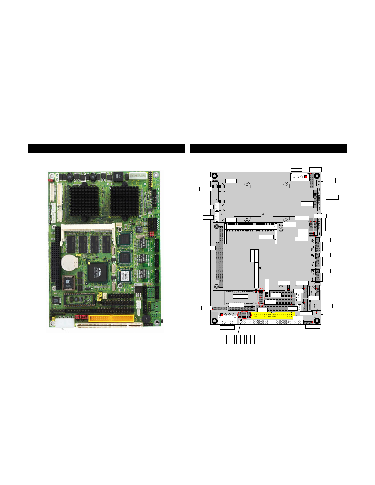
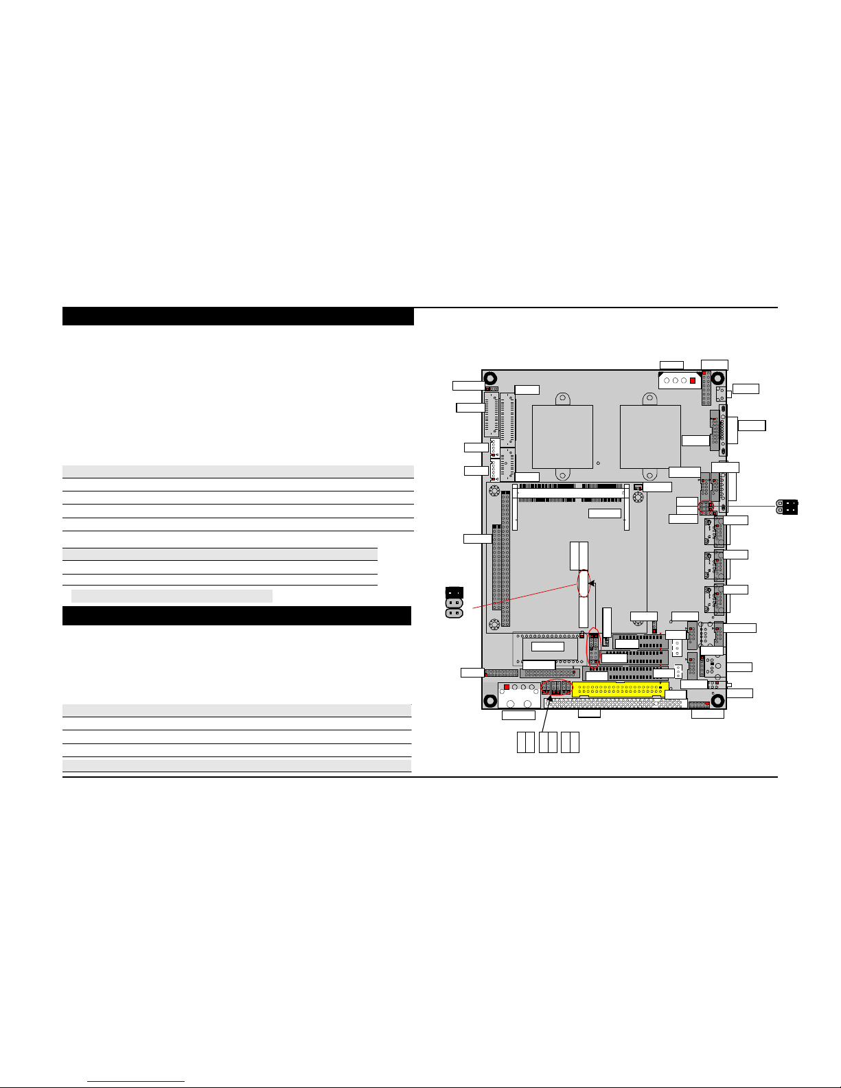
Board Image (boxheader version) Board Layout (Front)
PWR1 JFRT1
JVLCD1
LCD1
RES2
LVDS1
VGA1
INV1
VGA1
TV1
LCD2
CPUF1
AUDIO1
COM1
SODIM1
JV1
JV2
CDIN1
LAN3
PC104
LAN2
LAN1
DIO1
DOC1
COM2-4
IDE2
LPT1
FDD1
JCF1 USB2
EATX1
WOL1
SIR1
USB1
KBM1
IDE1
KBM1
LED1
PWR2
PCI1
LLED1
3301040 User's Manu al
8
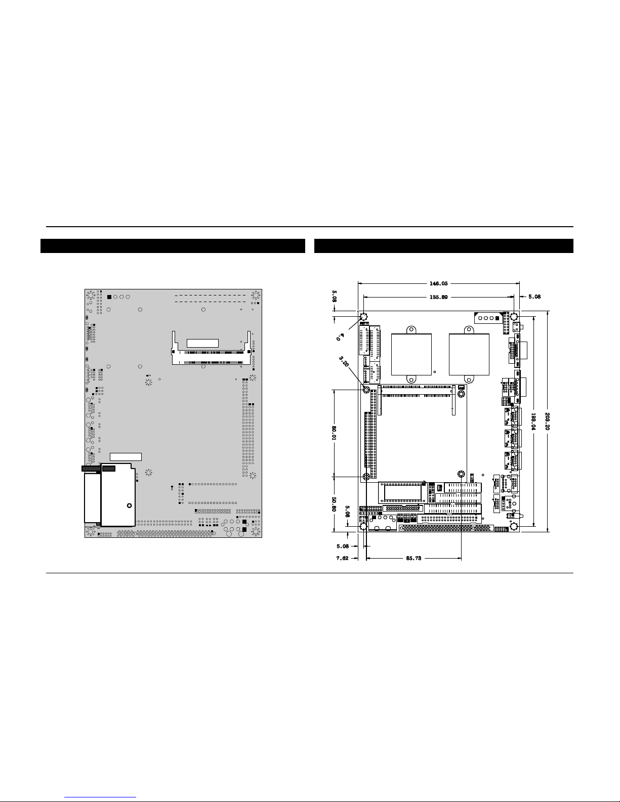
Board Layout (Back) Board Dimension
MPCI1
CFD1
3301040 User's Manu al
Unit:
mm
9
Jumper Quick Reference
Jumpers
Label Fun ction
JBAT1 Clear CMOS
JWT1 Watchdog Output
IDE2
Secondary IDE Connector (ATA 33)
KBM1 PS/2 Keyboard and Mouse
DOC1
DiskOnChip Connector
LAN1
10/100/1000 M LAN1 Connector
LAN2
10/100/1000 M LAN2 Connector
LAN3
10/100/1000 M LAN3 Connector
LPT1
Parallel Port
JRS2
COM2 RS-232C / 422 / 485 Selection
PWR1
4P Power Connector (180D)
JV1-2 COM1 Power Source Special Support
PWR2
4P Power Connector (90D)
JV3-4 COM2 Power Source Special Support
RES2
Reset Push Button
JV5-6 COM3 Power Source Special Support
IR1 Infrared (IR) Connector
JV7-8 COM4 Power Source Special Support
SYSF1
System Fan1 connector
JVLCD1 LVDS LCD Voltage selection
USB1
USB Port 0,1
JCF1 CFD Master/Slave Selection
USB2
USB Port 3,4
JPWR1 AT/ATX Power Type Selection
VGA1 CRT SVGA Connector
WOL1 Wake On LAN
Connector Quick Reference
Connectors
Lable
Function
EATX1
ATX feature connector
AUDIO1
Audio Interface Port
CDIN1
CD-ROM Audio Input
COM1
RS232 Serial Port: COM1
COM2-4 Serial Port: COM2~COM4
PC104
PC104 for ISA Interface Connector
CPUF1 CPU Fan1 connector
DIO1
Digital I/O Connector
FDD1
Floppy Disk Drive Connector
IDE1
Primary IDE Connector (ATA 33/66)
JFRT1
Switches & Indicators
SODIMM1 144-pin SODIMM Slot
CFD1 Compact Flash Disk
LLED1
LAN LED connector
LED1 Power / HDD LED
LCD1
18bit/24bit TTL Flat Panel Connector (DF13 40 pin)
LCD2
36bit TTL Flat Panel Connector (DF13 20 pin)
LVDS1
18/24bit LVDS Panel Connector (DF13 30 pin)
MPCI1 Mini PCI TYPE III Connector
INV1 LCD Inverter connector
TV1 TV-OUT Connector
PCI1
PCI Slot / Expansion PCI Slot
3301040 User's Manu al
10
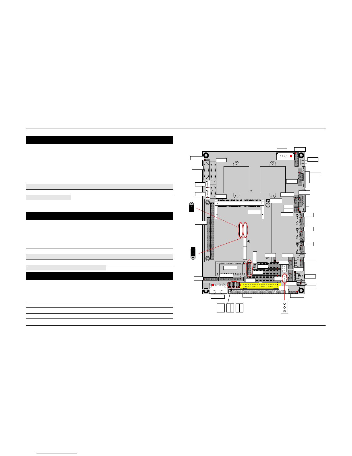
CMOS Jumper Settings
CMOS Operation (JBAT1)
Type : JBAT1: onboard 3-pin header
If the 3301040 refuses to b oot due to inappropriate CMOS settings here is how to proceed
to clear (reset) the C MOS to its def ault values.
CMOS Setup (JBAT1) J1 Stat us
Normal Operation 1-2
ON
Clear CMOS
2-3
ON
JVLCD1
LVDS1
INV1
LCD1
PWR1
VGA1
JFRT1
RES2
VGA1
default setting 1-2 ON
Watchdog Output
Mode Setting
Type : JWT1: onboard 3-pin (1*3) header
1
2
3
JW T1
TV1
PC104
LCD2
SODIM1
CPUF1
AUDIO1
JV1
JV2
CDIN1
COM1
LAN3
LAN2
Watchdog mode JWT1
Enabled for Active NMI(I/O Channel Check) 1-2
Enabled for System Reset 2-3
Disable Watchdog Timer
None
default setting Enabled f or System Reset
Wake On LAN
1
2
3
JBAT1
DIO1
DOC1
COM2-4
IDE2
LPT1
FDD1
JCF1 USB2
EATX1
WOL1
SIR1
LAN1
USB1
KBM1
Connector: WOL1
Type : onboard 3-pin wafer connector
Pin Description
1
5V_SB
PWR2
PCI1
IDE1
KBM1
LLED1
3
2
LED1
2
GND
1
WOL1
3
WOL_CTL
3301040 User's Manu al
11
Serial Port Selection (RS232C/422/485)
RS-232C/422/485 Mode select (JRS2)
Type : JRS2: onboard 6-pin(2*3) header
PWR1 JFRT1
RS-422/485 Mode on COM2
The onboard COM2 port c an be c onfigured to operate in R S-422 or RS-4 85 modes.
RS-422 modes differ in th e way RX/T X is being handled. Jump er JRS2 s witches
between RS-232C or R S-422/ 485 mod e. Al l of t he RS-232C/422/485 modes are available
on COM2.
COM2
Pin Defined: RS-232C RS-422 RS-485
Pin1 : DCD
Tx+ RTx+
JVLCD1
LVDS1
INV1
TV1
LCD1
LCD2
CPUF1
VGA1
AUDIO1
COM1
RES2
VGA1
Pin2 : RXD Tx- RTx-
JV1
3 2 1
JV1
Pin8 : CTS
Rx+
x
Pin9 : RI Rx- x
JRS2 Selection
1-2 3-4 5-6
RS-232C ON
OFF OFF
RS-422
OFF
ON
OFF
RS-485
OFF OFF
ON
1
PC104
2
SODIM1
JV2
CDIN1
LAN3
LAN2
LAN1
3 2 1
JV2
default setting RS-232C
3
4
COM1~COM4
Power Source Special Support
5
6
JCF1 USB2
USB1
Jumper : JV1 & J V2
JRS2
LPT1
EATX1
Type : Onboard 2*3 pin 2.0mm header
The voltage of COM 1 could be s elected by JV 1 & JV2.
COM1 Power Source JV1 JV2
DIO1
DOC1
COM2-4
IDE2
FDD1
WOL1
IDE1
KBM1
SIR1
KBM1
LED1
Standard 1-2 1-2
POS:12V on pin 9 2-3 1-2
POS:5V on pin 1 1-2 2-3
POS:5V on pin 1 a nd 12V on pi n 9 2-3 2-3
default setting Standard
3301040 User's Manu al
PWR2
PCI1
LLED1
12

Jumper : JV3 & J V4
Type : Onboard 2*3 pin 2.0mm header
The voltage of COM 2 could be s elected by JV 3 & JV4.
COM2 Power Source JV3 JV4
Standard 1-2 1-2
POS:12V on pin 9 2-3 1-2
POS:5V on pin 1 1-2 2-3
POS:5V on pin 1 a nd 12V on pi n 9 2-3 2-3
default setting Standard
JVLCD1
LVDS1
INV1
LCD1
PWR1
VGA1
JFRT1
RES2
VGA1
Jumper : JV5 & J V6
Type : Onboard 2*3 pin 2.0mm header
The voltage of COM 3 could be s elected by JV 5 & JV6.
TV1
LCD2
SODIM1
CPUF1
AUDIO1
JV1
JV2
CDIN1
COM1
LAN3
COM1 Power Source JV5 JV6
Standard 1-2 1-2
POS:12V on pin 9 2-3 1-2
POS:5V on pin 1 1-2 2-3
POS:5V on pin 1 a nd 12V on pi n 9 2-3 2-3
default setting Standard
Jumper : JV7 & J V8
Type : Onboard 2*3 pin 2.0mm header
The voltage of COM 4 could be s elected by JV 7 & JV8.
COM1 Power Source JV7 JV8
Standard 1-2 1-2
PC104
DIO1
DOC1
COM2-4
IDE2
LPT1
FDD1
JCF1 USB2
EATX1
WOL1
KBM1
IDE1
SIR1
LAN2
LAN1
USB1
KBM1
LED1
POS:12V on pin 9 2-3 1-2
POS:5V on pin 1 1-2 2-3
POS:5V on pin 1 a nd 12V on pi n 9 2-3 2-3
default setting Standard
PWR2
33
22
11
PCI1
3 3
3 3
2 2
2 2
1 1
1 1
LLED1
JV8 JV7
JV6 JV5
JV4 JV3
3301040 User's Manu al
13
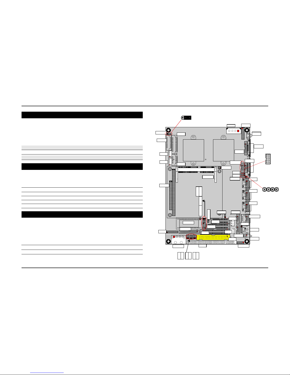
LVDS Voltage Selection
1 2 3
Type : JVLCD1: onboard 3-pin header
The voltage of LVDS panel could be s elected by JVLCD1 in 5V or 3.3V .
Mode JVLCD1
3.3V 2-3
5V
1-2
default setting 3.3V
JVLCD1
LVDS1
INV1
JVLCD1
LCD1
PWR1
VGA1
JFRT1
RES2
VGA1
1 2
Audio Interface
Connector : AUDIO1
Type : Onboard 10-pin box header
Pin Description Pin Descriptio
n
1
LINE IN LEFT
2
LINE IN RIGHT
3
GND
4
GND
5 MIC 6
NC
TV1
PC104
LCD2
SODIM1
CPUF1
AUDIO1
JV1
JV2
CDIN1
COM1
LAN3
LAN2
9 10
AUDIO1
4 3 2 1
7
GND
8
GND
LAN1
9
SPEAKER LEFT
10
SPEAKER RIGHT
CDIN Connector
Connector : CDIN1
Type : onboard 4-pin header
DIO1
DOC1
COM2-4
IDE2
LPT1
FDD1
JCF1 USB2
EATX1
WOL1
SIR1
USB1
KBM1
Pin Description Pin Description
1
CD Left
2
GND
PWR2
PCI1
IDE1
KBM1
LLED1
LED1
3
GND
4 CD Right
3301040 User's Manu al
14
 Loading...