

Global American 2808310 User Manual

2808310
System Board
User’s Manual

Copyright
This publication contains information that is protected by copyright. No part of it
may be reproduced in any form or by any means or used to make any transformation/adaptation without the prior written permission from the copyright holders.
This publication is provided for informational purposes only. The manufacturer
makes no representations or warranties with respect to the contents or use
of this manual and specifically disclaims any express or implied warranties of
merchantability or fitness for any particular purpose. The user will assume the
entire risk of the use or the results of the use of this document. Further, the
manufacturer reserves the right to revise this publication and make changes to
its contents at any time, without obligation to notify any person or entity of such
revisions or changes.
© 2012. All Rights Reserved.
Trademarks
All trademarks and registered trademarks of products appearing in this manual
are the properties of their respective holders.

FCC and DOC Statement on Class B
This equipment has been tested and found to comply with the limits for a Class B
digital device, pursuant to Part 15 of the FCC rules. These limits are designed to
provide reasonable protection against harmful interference when the equipment
is operated in a residential installation. This equipment generates, uses and can
radiate radio frequency energy and, if not installed and used in accordance with
the instruction manual, may cause harmful interference to radio communications.
However, there is no guarantee that interference will not occur in a particular
installation. If this equipment does cause harmful interference to radio or television reception, which can be determined by turning the equipment off and on,
the user is encouraged to try to correct the interference by one or more of the
following measures:
• Reorient or relocate the receiving antenna.
• Increase the separation between the equipment and the receiver.
• Connect the equipment into an outlet on a circuit different from that to which
the receiver is connected.
• Consult the dealer or an experienced radio TV technician for help.
Notice:
1. The changes or modifications not expressly approved by the party responsible
for compliance could void the user’s authority to operate the equipment.
2. Shielded interface cables must be used in order to comply with the emission
limits.

1
Introduction
Table of Contents
Copyright ...........................................................................................2
Trademarks ........................................................................................ 2
FCC and DOC Statement on Class B .............................................. 3
About this Manual ............................................................................. 6
Warranty .......................................................................................... 6
Static Electricity Precautions ............................................................. 7
Safety Measures ................................................................................. 7
About the Package ............................................................................ 8
Before Using the System Board ........................................................ 8
Chapter 1 - Introduction ..................................................................9
Specifications .................................................................................. 9
Features ...................................................................................... 12
Chapter 2 - Hardware Installation .................................................. 15
System Board Layout .................................................................... 15
System Memory ........................................................................... 16
Installing the DIM Module ......................................................... 17
CPU ............................................................................................ 19
Installing the CPU .................................................................... 19
Installing the Fan and Heat Sink ................................................ 21
Jumper Settings ............................................................................. 23
Clear CMOS Data ..................................................................... 23
PS/2 Power Select .................................................................... 24
USB Power Select ..................................................................... 25
Panel Power Select ................................................................... 26
COM1/COM2 RS232/RS422/RS485 Select.................................... 27
COM1/COM2 RS232/Power Select............................................... 28
Power-on Select ....................................................................... 29
CompactFlash Card Setting ....................................................... 30
Rear Panel I/O Ports ..................................................................... 31
PS/2 Mouse and PS/2 Keyboard Ports ......................................... 32
COM (Serial) Ports ................................................................... 33
HDMI Port ............................................................................... 34
DVI-I Port ............................................................................... 35
RJ45 LAN Ports ........................................................................ 36
4

Introduction
USB Ports................................................................................ 37
Audio ...................................................................................... 39
I/O Connectors ............................................................................ 41
S/PDIF Connector ..................................................................... 41
LVDS LCD Panel Connector ........................................................ 42
LCD/Inverter Power Connector ................................................... 42
Digital I/O Connectors .............................................................. 44
SATA (Serial ATA) Connectors .................................................... 45
Cooling Fan Connectors ............................................................. 46
Chassis Instrusion Connector .................................................... 47
Power Connectors .................................................................... 48
Standby Power LED .................................................................. 49
Front Panel Connectors ............................................................. 50
Expansion Slots ....................................................................... 51
Battery ................................................................................... 54
Chapter 3 - BIOS Setup .................................................................. 56
Overview .............................................................................................................. 56
AMI BIOS Setup Utility ................................................................. 58
Main ....................................................................................... 58
Advanced ................................................................................ 59
Chipset ................................................................................... 79
Boot ....................................................................................... 87
Security .................................................................................. 89
Save & Exit ............................................................................. 90
Updating the BIOS ........................................................................ 91
1
Chapter 4 - Supported Software ................................................... 92
Chapter 5 - RAID ........................................................................ 125
RAID Levels .......................................................................................................125
Settings ................................................................................................................126
Chapter 6 - Intel AMT Settings ................................................... 130
Overview ............................................................................................................130
Enable Intel® AMT in the AMI BIOS ............................................................131
Enable Intel® AMT in the Intel® Management Engine BIOS
Extension (MEBX) Screen ..............................................................................
133
Appendix A - NLITE and AHCI Installation Guide ....................... 158
Appendix B - Watchdog Sample Code ......................................... 170
Appendix C - System Error Message ............................................ 171
Appendix D - Troubleshooting ...................................................... 173
5

1
Introduction
About this Manual
An electronic file of this manual is included in the CD. To view the user’s manual
in the CD, insert the CD into a CD-ROM drive. The autorun screen (Main Board
Utility CD) will appear. Click “User’s Manual” on the main menu.
Warranty
1. Warranty does not cover damages or failures that arised from misuse of the
product, inability to use the product, unauthorized replacement or alteration
of components and product specifications.
2. The warranty is void if the product has been subjected to physical abuse,
improper installation, modification, accidents or unauthorized repair of the
product.
3. Unless otherwise instructed in this user’s manual, the user may not, under
any circumstances, attempt to perform service, adjustments or repairs on the
product, whether in or out of warranty. It must be returned to the purchase
point, factory or authorized service agency for all such work.
4. We will not be liable for any indirect, special, incidental or consequencial
damages to the product that has been modified or altered.
6

Introduction
Static Electricity Precautions
It is quite easy to inadvertently damage your PC, system board, components
or devices even before installing them in your system unit. Static electrical discharge can damage computer components without causing any signs of physical
damage. You must take extra care in handling them to ensure against electrostatic build-up.
1. To prevent electrostatic build-up, leave the system board in its anti-static bag
until you are ready to install it.
2. Wear an antistatic wrist strap.
3. Do all preparation work on a static-free surface.
4. Hold the device only by its edges. Be careful not to touch any of the components, contacts or connections.
5. Avoid touching the pins or contacts on all modules and connectors. Hold
modules or connectors by their ends.
1
Important:
Electrostatic discharge (ESD) can damage y
other components. Perform the upgrade instruction procedures described
at an ESD workstation only. If such a station is not available, you can
provide some ESD protection by wearing an antistatic wrist strap and
attaching it to a metal part of the system chassis. If a wrist strap is
unavailable, establish and maintain contact with the system chassis
throughout any procedures requiring ESD protection.
our processor, disk drive and
Safety Measures
To avoid damage to the system:
• Use the correct AC input voltage range.
To reduce the risk of electric shock:
• Unplug the power cord before removing the system chassis cover for installation or servicing. After installation or servicing, cover the system chassis
before plugging the power cord.
Battery:
• Danger of explosion if battery incorrectly replaced.
• Replace only with the same or equivalent type recommend by the manufacturer.
• Dispose of used batteries according to local ordinance.
7

1
Introduction
About the Package
The system board package contains the following items. If any of these items are
missing or damaged, please contact your dealer or sales representative for assistance.
One
Two Serial ATA data cables
Two COM port cables
Two USB port cables
One I/O shield
One DVD
One QR (Quick Reference)
2808310 board
Optional Items
USB port cable
COM port cable
Serial ATA data cable
Serial ATA power cable
I/O shield
The system board and accessories in the package may not come similar to the
information listed above. This may differ in accordance to the sales region or
models in which it was sold. For more information about the standard package in
your region, please contact your dealer or sales representative.
Before Using the System Board
Before using the system board, prepare basic system components.
If you are installing the system board in a new system, you will need at least the
following internal components.
• A CPU
• Memory module
• Storage devices such as hard disk drive, CD-ROM, etc.
You will also need external system peripherals you intend to use which will normally include at least a keyboard, a mouse and a video display monitor.
8
Chapter 1 - Introduction
Specifications
1
Introduction
Processor
Chipset
System Memory
Expansion Slots
• Socket G2 988B for:
rd
Generation Intel® CoreTM processors (22nm process
- 3
technology)
: Intel
: Intel
: Intel
- 2
: Intel
: Intel
: Intel
: Intel
• Intel® QM77 Express chipset
• Two 204-pin SODIMM sockets
• Supports DDR3 SODIMM
DDR3 1066/1333/1600MHz DDR3 1066/1333MHz (i5/
• Supports DDR3L SODIMM
- 1066/1333MHz when operating at 1.35V
- 1066/1333/1600MHz when operating at 1.5V
• Supports dual channel memory interface
• Supports up to 16GB system memory
• DRAM device technologies: 1Gb, 2Gb and 4Gb DDR3 DRAM
technologies are supported for x8 and x16 devices, unbuffered, non-ECC
• 1 PCIe x16 slot
- Supports Gen 3.0 (3rd generation processors)
- Supports Gen 2.0 (2nd generation processors)
- Configurations (supported only via a riser card):
: One x8 (GFX) and two x4 (I/O)
: Two x8 (GFX, I/O)
: One x16 (GFX, I/O)
• 2 PCIe x1 gold fingers for customized expansion (PCI or
Mini PCIe via a riser card
• 1 Mini PCIe x1 slot (PCIe and USB signals)
®
Core™ i7-3610QE (6M Cache, up to 3.3 GHz); 45W
®
Core™ i5-3610ME (3M Cache, up to 3.3 GHz); 35W
®
Core™ i3-3120ME (3M Cache, 2.4 GHz); 35W
nd
Generation Intel® CoreTM processors (32nm process
technology)
®
Core™ i7-2710QE (6M Cache, up to 3.0 GHz); 45W
®
Core™ i5-2510E (3M Cache, up to 3.1 GHz); 35W
®
Core™ i3-2330E (3M Cache, 2.2 GHz); 35W
®
Celeron® B810 (2M Cache, 1.6 GHz); 35W
3rd Generation Processors 2nd Generation Processors
Celeron)
DDR3 1600MHz (i7)
9

1
Introduction
Graphics
®
• Intel
• Display ports: HDMI, 2 DVI-I (1 supports DVI-D signal
only), and LVDS
• Display resolution up to 1920x1200
• LVDS: Single Channel - 18/24-bit; Dual Channel - 36/48-bit
• Intel
• DirectX Video Acceleration (DXVA) for accelerating video
processing - Full AVC/VC1/MPEG2 HW Decode
• Supports DirectX 11/10.1/10/9 and OpenGL 3.0
HD Graphics
®
Clear Video Technology
Audio
LAN
Serial ATA
Intel Active
Management
Technology
(AMT)
TPM (optional)
USB interface
Rear Panel I/O
Ports
• Realtek ALC886 5.1-channel High Defi nition Audio
• Audio outputs: Mic-in/Center+Subwoofer, line-in/surround and
line-out
• S/PDIF audio interface
• Intel® WG82579LM with iAMT8.0 Gigabit Ethernet Phy
®
• Intel
• Integrated 10/100/1000 transceiver
• Fully compliant with IEEE 802.3, IEEE 802.3u, IEEE 802.3ab
• Supports wire management
• 4 Serial ATA ports
- 2 SATA 3.0 ports with data transfer rate up to 6Gb/s
- 2 SATA 2.0 ports with data transfer rate up to 3Gb/s
• Integrated Advanced Host Controller Interface (AHCI) con-
• Supports RAID 0/1/5/10
• Supports iAMT8.0
• Out-of-band system access
• Remote troubleshooting and recovery
• Hardware-based agent presence checking
• Proactive alerting
• Remote hardware and software asset tracking
• Provides a Trusted PC for secure transactions
• Provides software license protection, enforcement and
• XHCI Host Controller supports up to 4 super speed USB 3.0
• 1 mini-DIN-6 port for PS/2 mouse/keyboard
• 4 USB 3.0/2.0/1.1 ports
• 2 USB 2.0/1.1 ports
• 1 DB-9 serial port
- Supports RS232/422/485 (RS232 and/or Power)
• 1 HDMI port
• 2 DVI-I ports (1 supports DVI-D signal only)
• 2 RJ45 LAN ports
• Mic-in/Center+Subwoofer, line-in/surround and line out
WG82574L PCI Express Gigabit Ethernet controller
troller
password protection
ports
jacks
10

Introduction
1
I/O Connectors
BIOS
Energy Efficient
Design
Damage Free
Intelligence
Temperature
Humidity
Dimensions
• 2 connectors for 4 external USB 2.0/1.1 ports
• 5 connectors for 5 external serial ports
- 1 RS232/422/485 (RS232 and/or P
- 4 RS232
• 1 LVDS LCD panel connector
• 1 LCD/inverter power connector
• 1 8-bit Digital I/O connector
• 1 front audio connector for line-out and mic-in jacks
• 1 S/PDIF connector
• 4 Serial ATA ports (2 SATA 3.0; 2 SATA 2.0)
• 1 24-pin ATX power connector
• 1 chassis intrusion connector
• 1 front panel connector
• 2 fan connectors
• AMI BIOS
• 64Mbit SPI BIOS
• Supports ErP Lot6 power saving (optional)
• ACPI v3.0 specification
• System Power Management
• Wake-On-Events include:
- Wake-On-PS/2 KB/Mouse
- Wake-On-USB KB/Mouse
- Wake-On-LAN
- RTC timer to power-on the system
• AC power failure recovery
• Monitors CPU/system temperature and overheat alarm
• Monitors VCORE/1.05V/DDR/3.3V/5V/12V voltages and failure alarm
• Monitors CPU/system fan speed and failure alarm
• Read back capability that displays temperature, voltage and
fan speed
• Watchdog timer function
- Watchdog timeout programmable via software from 1 to
255 seconds
o
• Operating: 0
• Storage: -20
• 10% to 90%
• Mini-ITX form factor
• 170mm (6.7”) x 170mm (6.7”)
C to 60oC
o
C to 85oC
ower)
11

1
Introduction
Features
Watchdog Timer
The Watchdog Timer function allows your application to regularly “clear” the system at the set time interval. If the system hangs or fails to function, it will reset
at the set time interval so that your system will continue to operate.
DDR3
DDR3 delivers increased system bandwidth and improved performance. It offers
peak data transfer rate of up to 21 Gb/s bandwidth. The advantages of DDR3
are its higher bandwidth and its increase in performance at a lower power than
DDR2.
Graphics
The integrated Intel HD graphics for graphics intensive applications delivers exceptional 3D, 2D and video capabilities. It supports HDMI, DVI-I and LVDS interfaces.
DVI
DVI (Digital Visual Interface) is a form of video interface technology made to
maximize the quality of flat panel LCD monitors and modern video graphics
cards. Data is transmitted using the TMDS (Transition Minimized Differential Signaling) protocol, providing a digital signal from the PC’s graphics subsystem to
the display.
PCI Express
PCI Express is a high bandwidth I/O infrastructure that possesses the ability to
scale speeds by forming multiple lanes. The PCI Express architecture provides a
high performance graphics infrastructure by enhancing the capability of a x16 PCI
Express lane to provide 4 Gigabytes per second transfer rate.
Intel Active Management Technology (AMT)
Intel Active Management Technology (Intel® AMT) allows remote access and management of networked systems even while PCs are powered off, remotely repair
systems after OS failures and has the capability to remotely update all systems
with the latest security software.
Audio
12
The Realtek ALC886 audio codec provides 5.1-channel High Definition audio output.

Introduction
Serial ATA
Serial ATA is a storage interface that is compliant with SATA 1.0a specification. SATA 3.0 supports speed up to 6Gb/s while SATA 2.0 supports speed up to
3Gb/s. This improves hard drive performance faster than the standard parallel
ATA whose data transfer rate is 100MB/s. The board supports RAID 0/1/5/10.
Gigabit LAN
The Intel WG82579LM PHY and Intel WG82574L PCI Express Gigabit controllers
support up to 1Gbps data transmission.
USB
The system board supports the new USB 3.0. It is capable of running at a maximum transmission speed of up to 5 Gbit/s (625 MB/s) and is faster than USB 2.0
(480 Mbit/s, or 60 MB/s) and USB 1.1 (12Mb/s). USB 3.0 reduces the time required for data transmission, reduces power consumption, and is backward compatible with USB 2.0. It is a marked improvement in device transfer speeds
between your computer and a wide range of simultaneously accessible external Plug and Play peripherals.
1
Wake-On-LAN
This feature allows the network to remotely wake up a Soft Power Down (SoftOff) PC. It is supported via the onboard LAN port or via a PCI LAN card that uses
the PCI PME (Power Management Event) signal. However, if your system is in the
Suspend mode, you can power-on the system only through an IRQ or DMA interrupt.
Important:
The 5V_standby power source of y
≥720mA.
our power supply must support
Wake-On-PS/2
This function allows you to use the PS/2 keyboard or PS/2 mouse to power-on
the system.
Important:
The 5V_standby power source of y
≥720mA.
our power supply must support
13
1
Introduction
Wake-On-USB
This function allows you to use a USB keyboard or USB mouse to wake up a system from the S3 (STR - Suspend To RAM) state.
Important:
ou are using the Wake-On-USB Keyboard/Mouse function for 2 USB
If y
ports, the 5V_standby power source of your power supply must support
≥1.5A. For 3 or more USB ports, the 5V_standby power source of your
power supply must support ≥2A.
RTC Timer
The RTC installed on the system board allows your system to automatically power-on on the set date and time.
ACPI STR
The system board is designed to meet the ACPI (Advanced Configuration and
Power Interface) specification. ACPI has energy saving features that enables PCs
to implement Power Management and Plug-and-Play with operating systems that
support OS Direct Power Management. ACPI when enabled in the Power Management Setup will allow you to use the Suspend to RAM function.
With the Suspend to RAM function enabled, you can power-off the system at
once by pressing the power button or selecting “Standby” when you shut down
Windows
closing files, applications and operating system. This is because the system is
capable of storing all programs and data files during the entire operating session
into RAM (Random Access Memory) when it powers-off. The operating session will
resume exactly where you left off the next time you power-on the system.
®
without having to go through the sometimes tiresome process of
Important:
The 5V_standby power source of y
720mA.
our power supply must support
Power Failure Recovery
When power returns after an AC power failure, you may choose to either poweron the system manually or let the system power-on automatically.
14
Chapter 2 - Hardware Installation
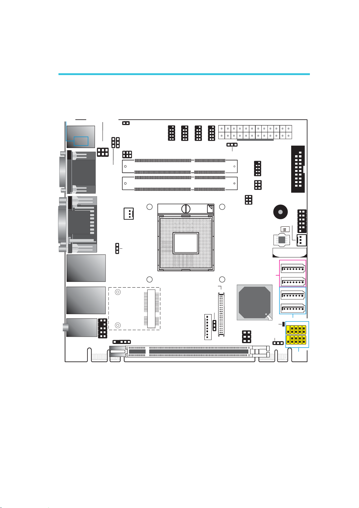
System Board Layout
COM1 RS232/Power
USB 2.0
Line-in/ Surround
Line-out
Mic-in/ Center+Subwoofer
select (JP1)
PS/2
Mouse/KB
USB 8
USB 9
COM 1
HDMI
DVI-I
DVI-I
LAN 1
USB3.0 (0-1)
LAN 2
USB3.0 (2-3)
1
1
1
6
5
9
Front audio
1
1
PS/2 power
select (JP2)
2
1
1
CPU fan
USB 0-1/ 2-3 power
select (JP6)
1
JP1
2
1
USB 8-9 power
select ( )JP8
(Top: DVI-D signal only)
10
2
Chassis
intrusion
6
COM1 RS232/422/485
select ( )JP4
5
S/PDIF
9
999
1
2
1
2
COM6
COM5
DDR3_2 SODIMM
DDR3_1 SODIMM
Socket G2
rPGA 988B
Mini PCIe
LCD/Inverter
PCIe x16
1
2
COM4
LVDS LC D
Backlight
level (JP11)
power
2
COM3
panel
1
1
1
1
13
Power-o n
select ( )JP7
21
40 39
1
Hardware Installation
ATX Pow er
9
1
2
5
6
2
1
6
5
1
2
COM2 RS232/Power
select (JP3)
SPI Flash BIOS
SATA 3.0
Intel
QM77
Panel po wer
select ( )JP9
1
5
2
6
Power L ED
Clear CMOS
COM2
COM2 RS232/
422/485 Select
(JP5)
Standby
Buzzer
SW1
(JP10)
1
12
24
System fan
ON
1
2
Battery
SATA 0
SATA 1
SATA 4
SATA 5
SATA 2.0
USB 6-7
9
10
9
USB 4-5
19
1
2
DIO
Front
panel
1
11
USB 2.0
1
1
1
1
1
2
1
2
1
2
PCIe x1 PCIe x1
15
2
Hardware Installation
Important:
Electrostatic discharge (ESD) can damage your system board, processor,
disk drives, add-in boards, and other components. Perform the upgrade
instruction procedures described at an ESD workstation only. If such a
station is not available, you can provide some ESD protection by wearing
an antistatic wrist strap and attaching it to a metal part of the system
chassis. If a wrist strap is unavailable, establish and maintain contact
with the system chassis throughout any procedures requiring ESD protection.
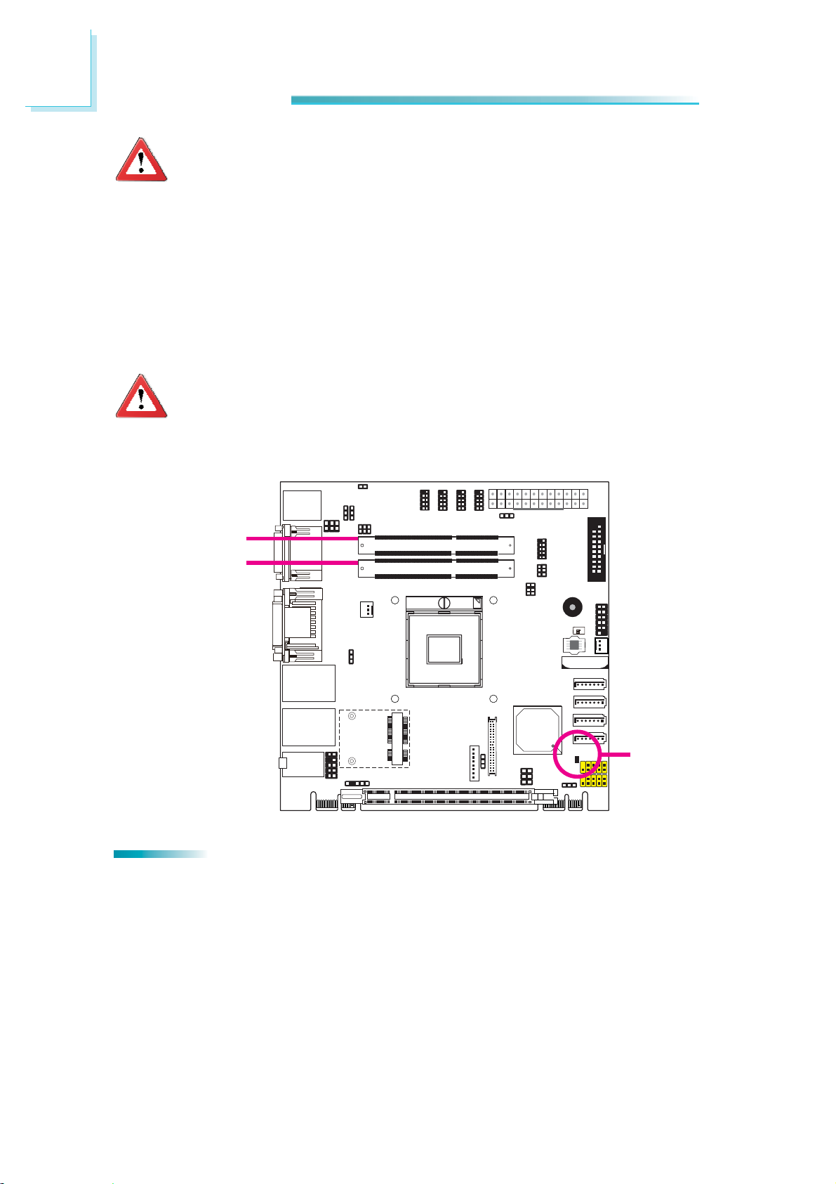
System Memory
Important:
When the Standby Power LED lit red, it indicates that there is power on
the system board. Power-off the PC then unplug the power cord prior to
installing any devices. Failure to do so will cause severe damage to the
motherboard and components.
DDR3-2
DDR3-1
Features
• Two 204-pin DDR3 SODIMM sockets
• Supports 1066/1333/1600MHz DDR3 SDRAM
Standby
Power LED
16
• Dual channel memory interface
• Supports maximum of 16GB system memory
Hardware Installation
Installing the DIM Module
Note:
The system board used in the following illustrations may not resemble
the actual board. These illustrations are for reference only.
1. Make sure the PC and all other peripheral devices connected to it has been
powered down.
2. Disconnect all power cords and cables.
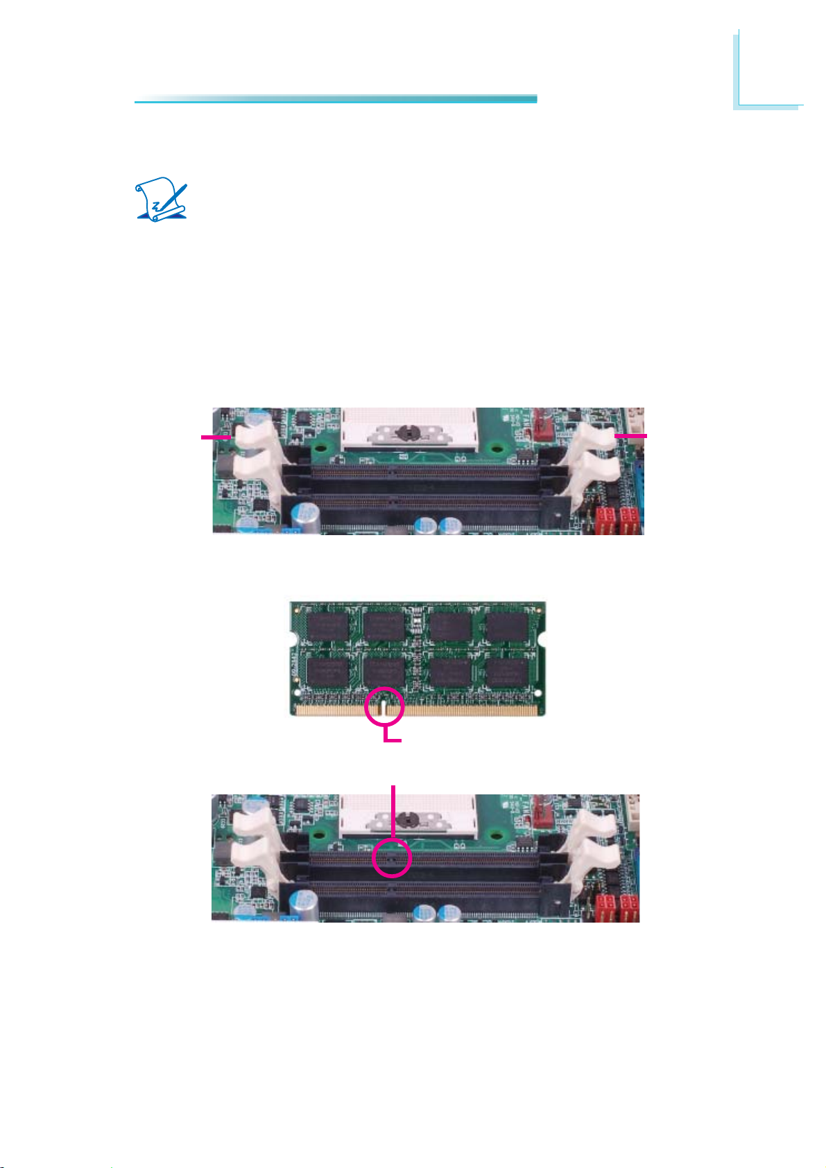
3. Locate the DIMM socket on the system board.
4. Push the “ejector tabs” which are at the ends of the socket to the side.
2
Ejector tab
5. Note how the module is keyed to the socket.
Notch
Key
Ejector tab
17
2
Hardware Installation
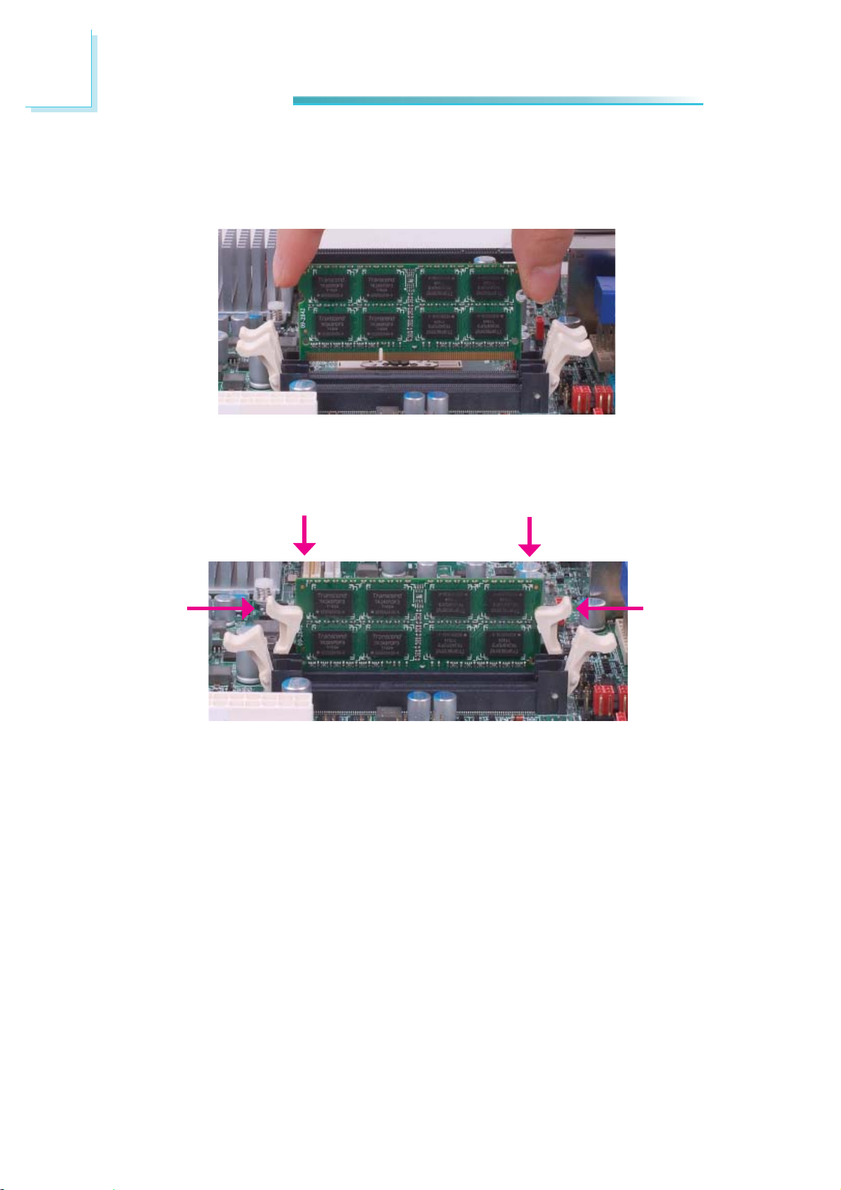
6. Grasping the module by its edges, position the module above the socket with
the “notch” in the module aligned with the “key” on the socket. The keying
mechanism ensures the module can be plugged into the socket in only one
way.
7. Seat the module vertically, pressing it down fi rmly until it is completely seat-
ed in the socket. The ejector tabs at the ends of the socket will automatically
snap into the locked position to hold the module in place.
18
Hardware Installation
CPU
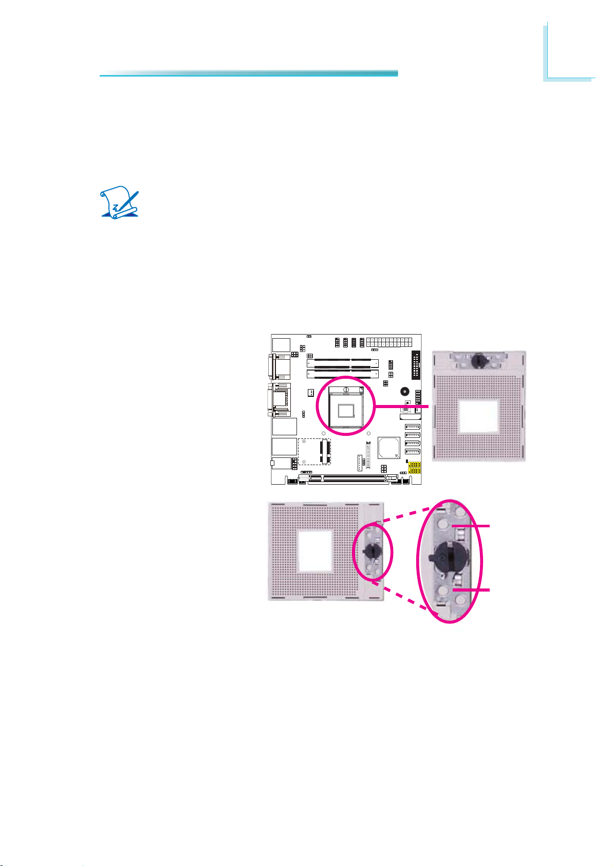
Overview
The system board is equipped with a surface mount PGA 988B CPU socket.
Note:
The system board used in the following illustr
the actual one. These illustrations are for reference only.
Installing the CPU
1. Make sure the PC and all other peripheral devices connected to it has been
powered down.
2. Disconnect all power cords and cables.
3. Locate the PGA 988B socket on the system board.
ations may not resemble
2
4. Make sure the screw is in
its unlock position. If it’s
not, use a screwdriver to
turn the screw to its unlock position.
Lock
Unlock
19
2
Hardware Installation
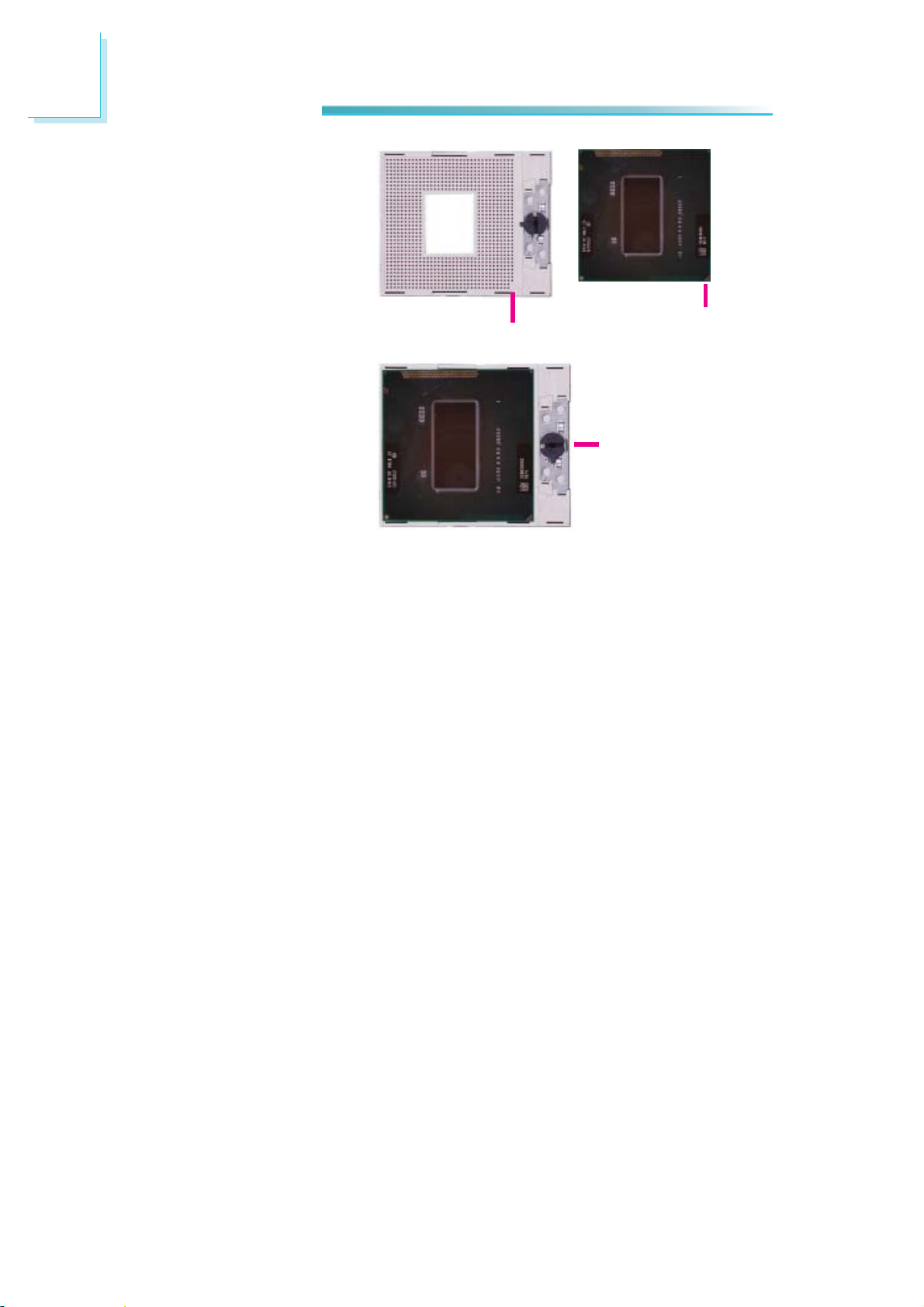
5. Position the CPU above the
socket. The gold triangular
mark on the CPU must
align with pin 1 of the CPU
socket.
Important:
Handle the CPU by its edges and a
pins.
6. Insert the CPU into the
socket until it is seated
in place. The CPU will fi t
in only one orientation
and can easily be inserted
without exerting any force.
Use a screwdriver to turn
the screw to its lock position.
void touching the
Gold triangular mark
Pin 1
Screw in locked
position
Important:
Do not force the CPU into
the sock
CPU into the socket may
bend the pins and damage
the CPU.
et. Forcing the
20
Hardware Installation
Installing the Fan and Heat Sink
The CPU must be kept cool by using a CPU fan with heat sink. Without suffi cient
air circulation across the CPU and heat sink, the CPU will overheat damaging
both the CPU and system board.
Note:
•
Use only certifi ed fan and heat sink.
• Your fan and heat sink package usually contains the fan and heat sink
assembly, and an installation guide. If the installation procedure in the
installation guide differs from the one in this section, please follow the
installation guide in the package.
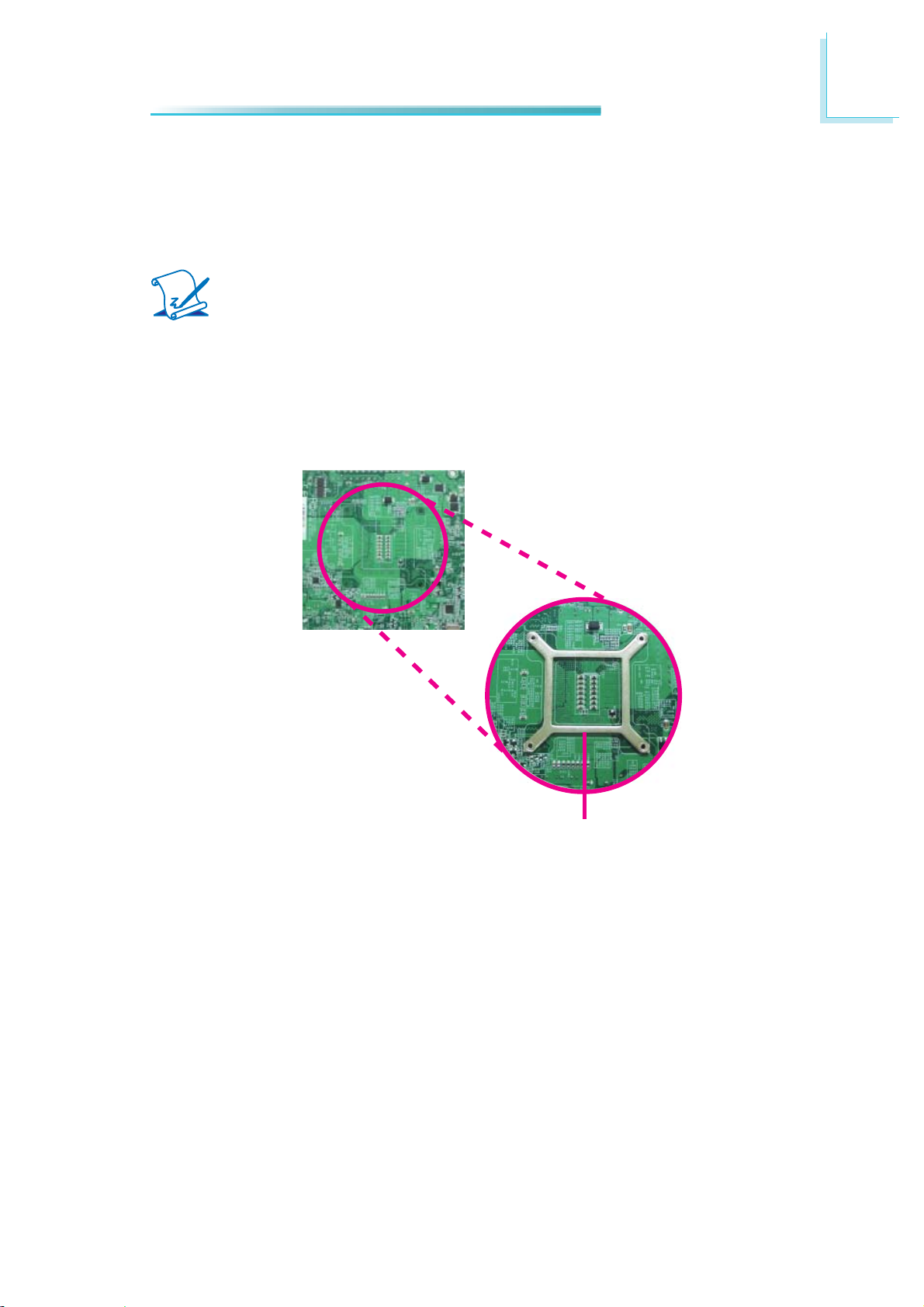
1. On the solder side of the board, match the retention module base to the
mounting holes around the CPU socket.
2
Retention module base
2. Turn to the component side of the board making sure the retention module
base is positioned and fi tted properly under the board.
3. Apply a thin layer of thermal paste on top of the CPU. Do not spread the
paste all over the surface. When you later place the heat sink on top, the
compound will disperse evenly.
21
2
Hardware Installation
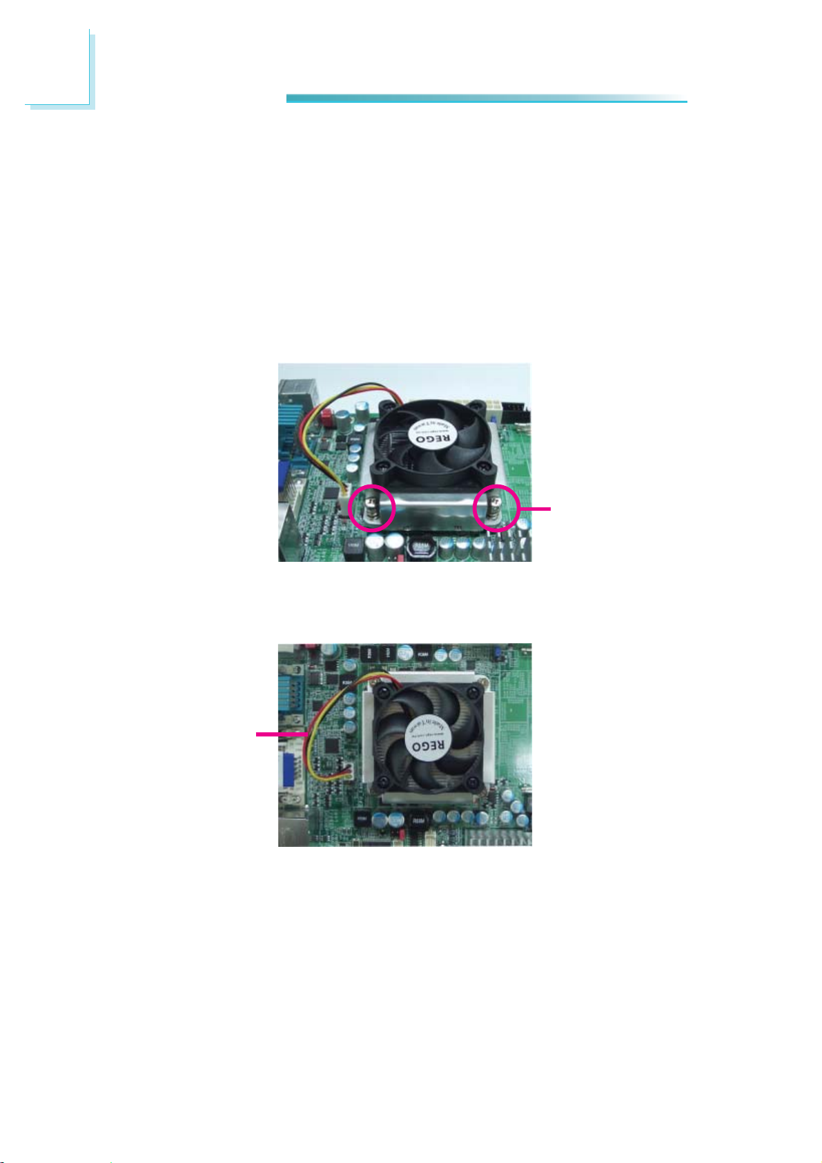
4. Place the fan / heat sink assembly on top of the CPU. The 4 screws around
the heat sink must match the screw holes of the retention module base. We
strongly recommend using this type of fan / heat sink assembly because it
provides adequate cooling to the components of the system board.
Turn each Phillips head screw half way down fi rst to initially stabilize the heat
sink onto the board, then fi nally tighten each screw.
Important:
Do not turn the fi
This is to avoid imbalance which might cause cracks or fractures to the CPU
and/or heat sink assembly.
rst screw all the way down followed by the next and so on.
Mounting
screw
5. Connect the CPU fan’s cable connector to the CPU fan connector on the system board.
CPU fan cable
22
Jumper Settings
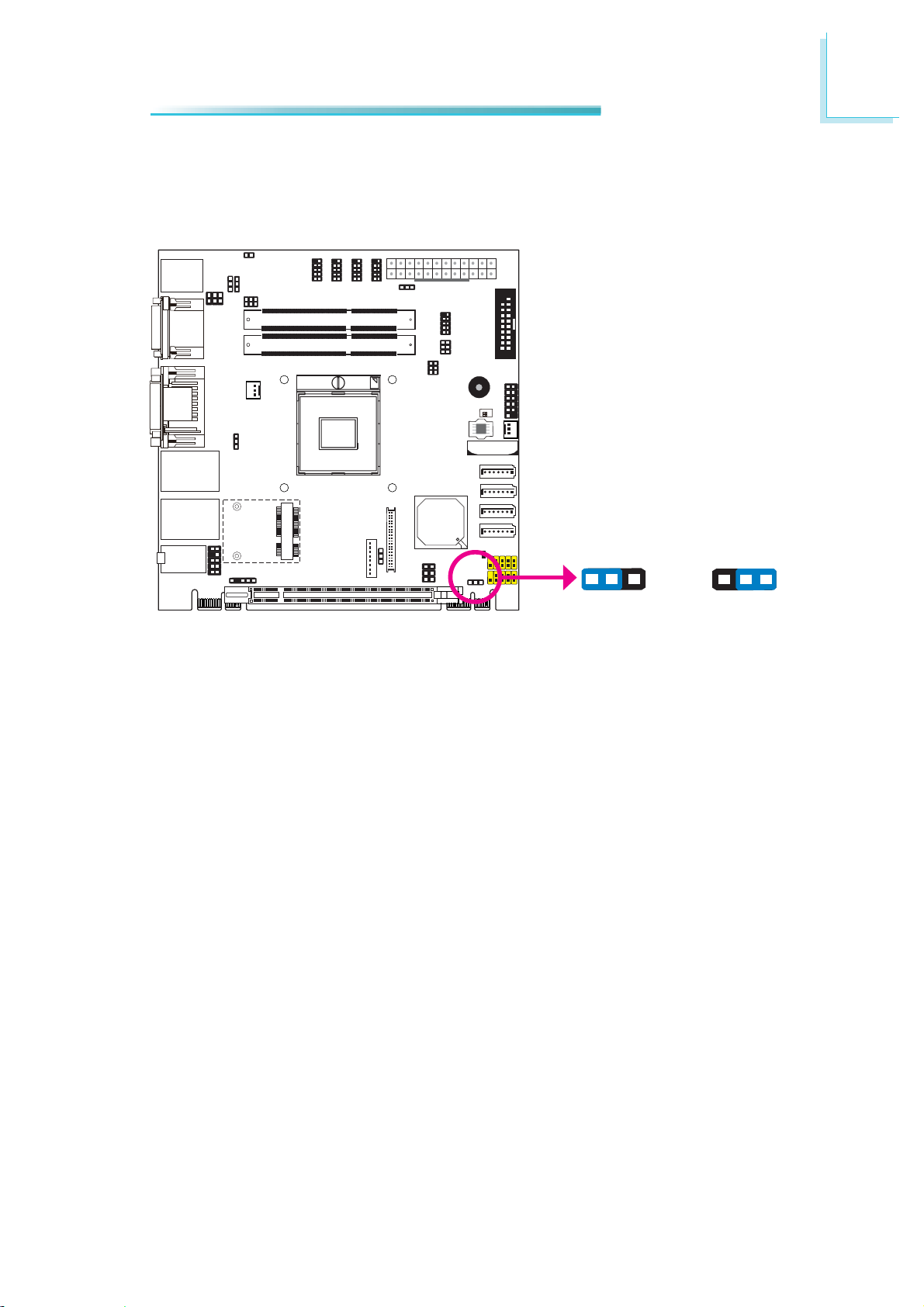
Clear CMOS Data
2
Hardware Installation
JP10
1-2 On: Normal
(default)
If you encounter the following,
a) CMOS data becomes corrupted.
b) You forgot the supervisor or user password.
you can reconfi gure the system with the default values stored in the ROM BIOS.
To load the default values stored in the ROM BIOS, please follow the steps below.
1. Power-off the system and unplug the power cord.
2. Set JP10 pins 2 and 3 to On. Wait for a few seconds and set JP10 back to its
default setting, pins 1 and 2 On.
3. Now plug the power cord and power-on the system.
312
Clear CMOS Data
312
2-3 On:
23
2
Hardware Installation
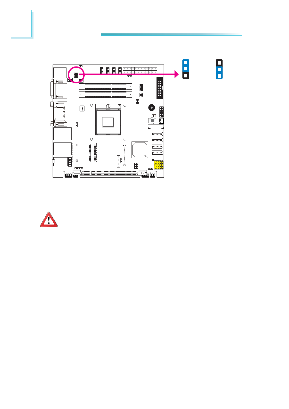
PS/2 Power Select
JP2
1-2 On: +5V
JP2 is used to select the power of the PS/2 keyboard and PS/2 mouse ports. Selecting +5V_standby will allow you to use the PS/2 keyboard or PS/2 mouse to
wake up the system.
1
2
3
(default)
+5V_standby
1
2
3
2-3 On:
Important:
The +5VSB power source of your power supply must support ≥720mA.
24
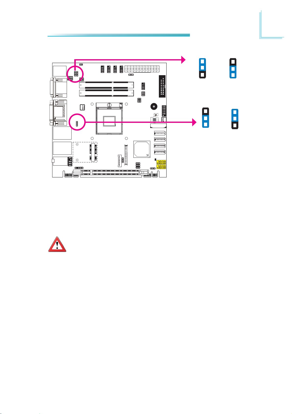
USB Power Select
2
Hardware Installation
USB 8-9
(JP8)
1-2 On: +5V
USB 0-1/2-3
(JP6)
1
2
3
(default)
3
2
1
1-2 On: +5V
(default)
1
2
3
2-3 On:
+5V_standby
3
2
1
2-3 On:
+5V_standby
This jumper is used to select the power of the USB ports. Selecting +5V_standby
will allow you to use a USB device to wake up the system.
Important:
ou are using the Wake-On-USB Keyboard/Mouse function for 2 USB
If y
ports, the +5V_standby power source of your power supply must support ≥1.5A. For 3 or more USB ports, the +5V_standby power source of
your power supply must support ≥2A.
25

2
Hardware Installation
Panel Power Select
JP9
1
3
5
1-2 On: +12V
JP9 is used to select the power supplied to the LCD panel.
Important:
Before powering-on the system, mak
LCD panel’s specifi cation. Selecting the incorrect voltage will seriously
damage the LCD panel.
2
4
6
1
3
5
3-4 On: +5V
e sure JP9’s setting matches the
2
4
6
1
3
5
5-6 On: +3.3V
(default)
2
4
6
26
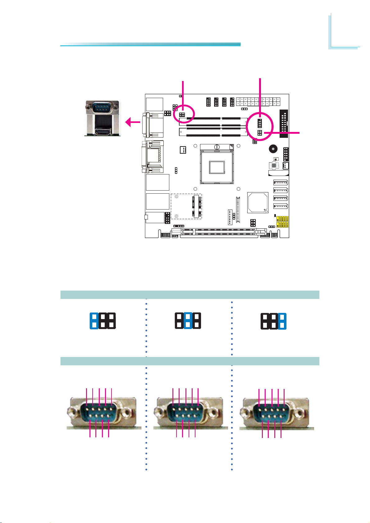
COM1/COM2 RS232/RS422/RS485 Select
JP4
COM 1
2
Hardware Installation
COM 2
JP5
JP4 (for COM1) and JP5 (for COM2) are used to confi gure the COM ports to
RS232, RS422 (Full Duplex) or RS485.
The pin function of the COM ports will vary according to the jumper’s setting.
JP4/JP5
64
2
531
1-2 On: RS232
(default)
DCD-TDRD
12345
DTR-
GND
3-4 On: RS422
Full Duplex
RXD+
12345
2
COM 1
TXD+
RXD-
64
531
TXD-
N.C.
64
2
531
5-6 On: RS485
DATA+
N.C.
DATA-
N.C.
N.C.
12345
6789
RI-
RTS-
CTS-
DSR-
RS232 RS422
6789
Full Duplex
N.C.
N.C.
N.C.
N.C.
6789
N.C.
N.C.
N.C.
RS485
N.C.
27
2
Hardware Installation
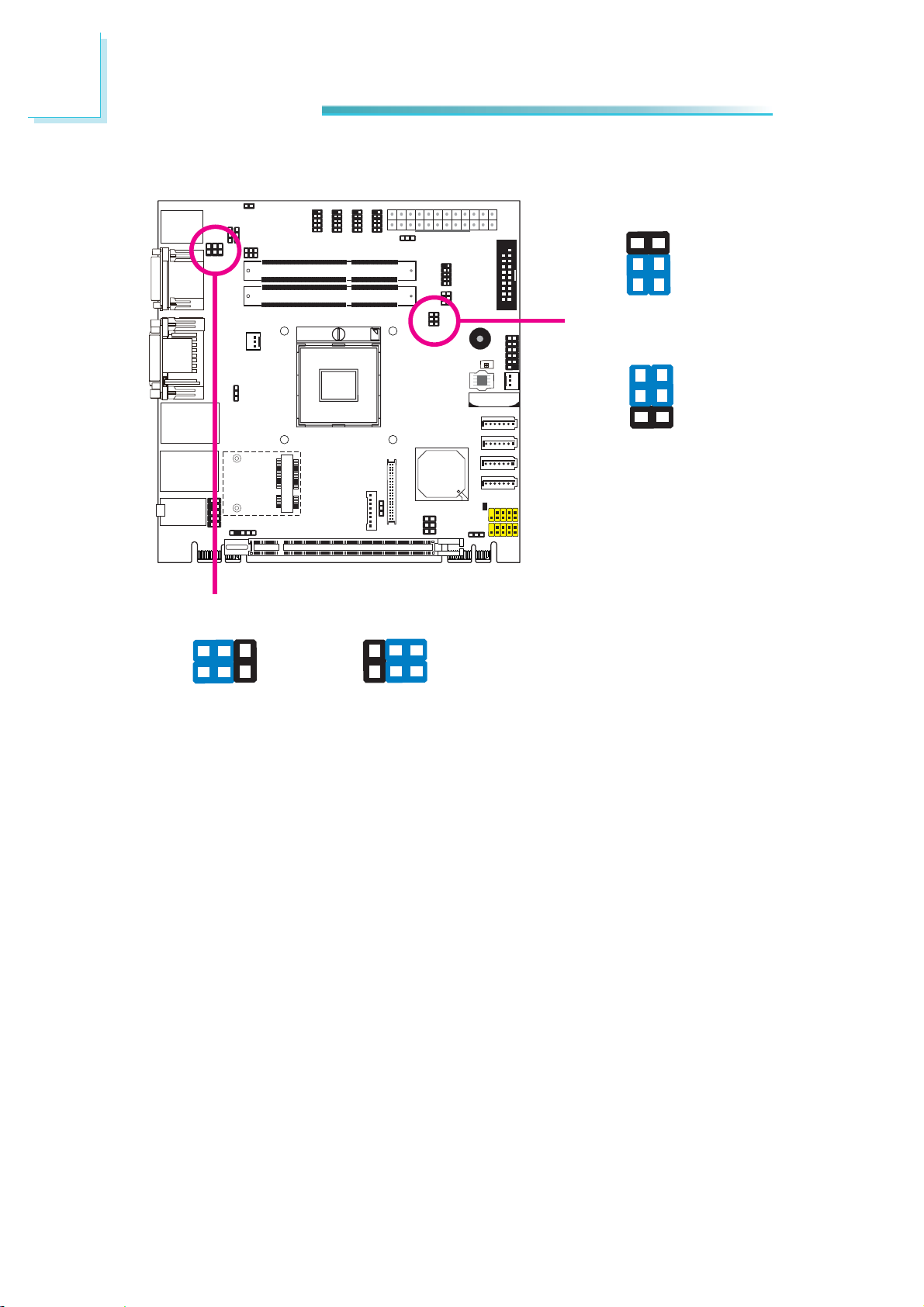
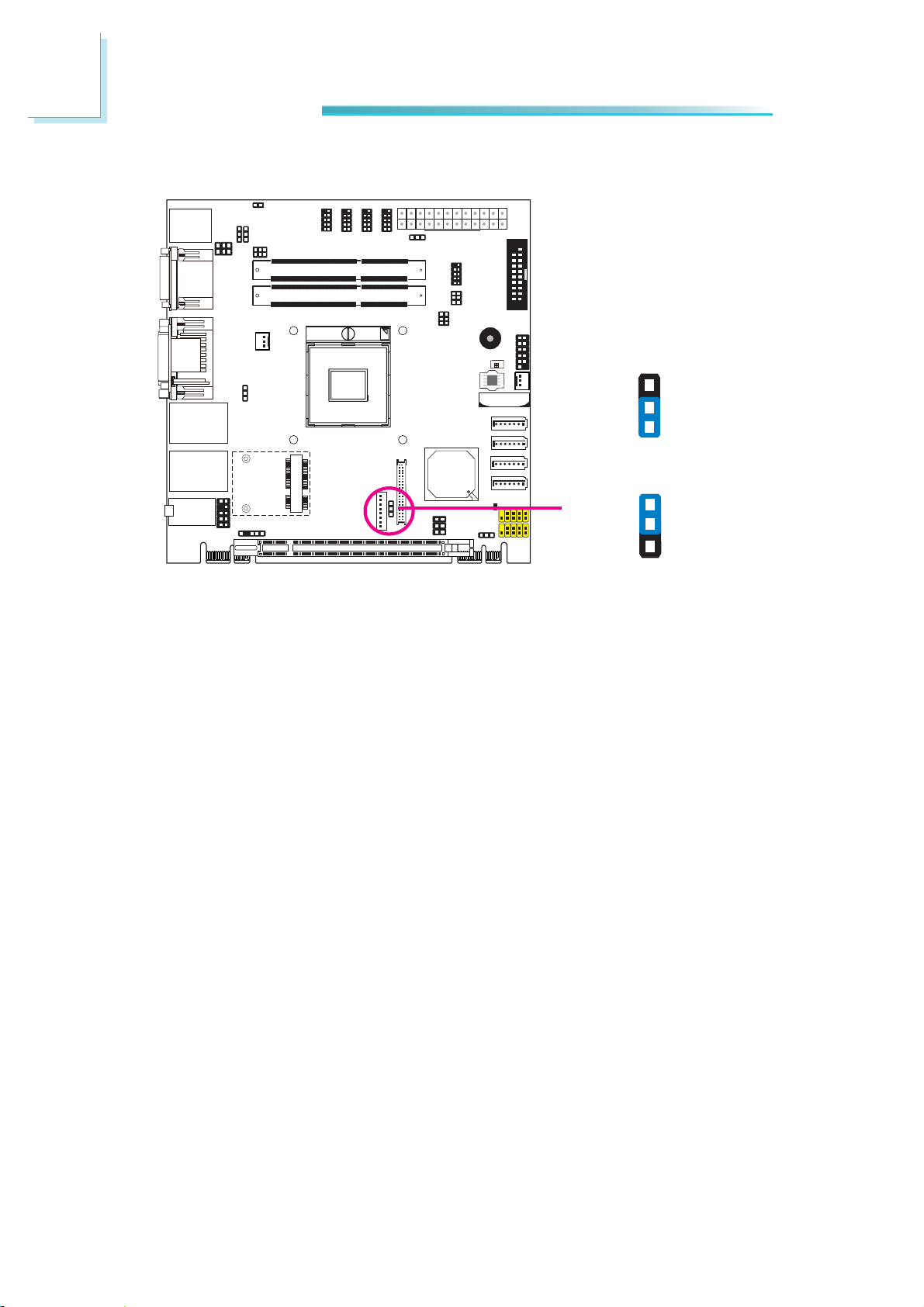
COM1/COM2 RS232/Power Select
JP1
2 4 6
2 4 6
6
4
2
JP3
1-3, 2-4 On: RS232
(default)
6
4
2
3-5 (+12V), 4-6 (+5V)
On: RS232 with power
5
3
1
5
3
1
1 3 5
1-3, 2-4 On: RS232
(default)
1 3 5
3-5 (+12V), 4-6 (+5V)
On: RS232 with power
28
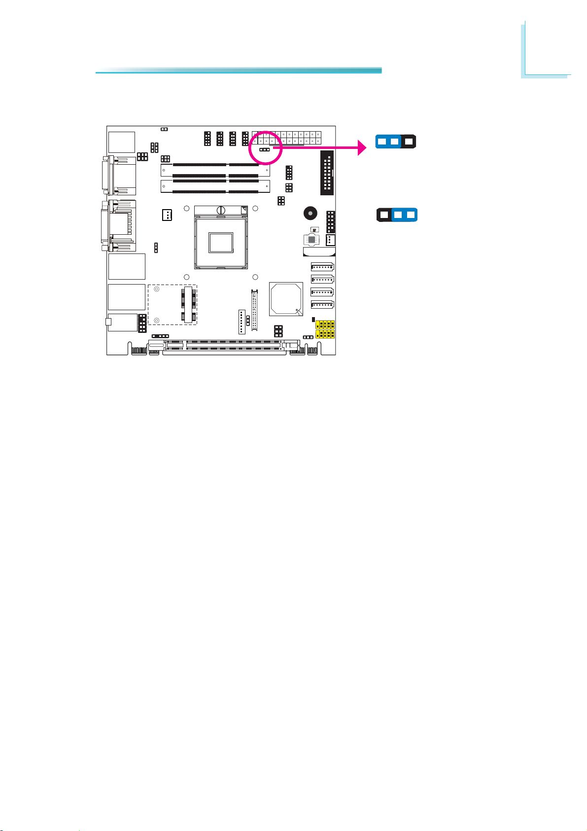
Power-on Select
2
Hardware Installation
To power-on via WOL after G3:
1. Set JP7 pins 2 and 3 to On.
JP7
312
1-2 On:
Power-on via power button
(default)
312
2-3 On:
Power-on via AC power; or
Power-on via WOL after G3
2. Set the “After G3” fi eld to Power Off/WOL.
3. Set the “GbE Wake Up From S5” to Enabled.
The BIOS fi elds are in the “South Bridge Confi guration” submenu (Chipset menu)
of the AMI BIOS utility.
To power-on via AC Power:
1. Set JP7 pins 2 and 3 to On.
2. Set the “After G3” fi eld to Power On.
29
2
Hardware Installation
Backlight Level Select
3
2
1
1-2 On: +5V
(default)
JP 11
3
2
1
2-3 On: +3.3V
JP 11 is used to select the backlight level +5V or +3.3V.
30
 Loading...