

Global American 2808220 User Manual

2808220
Intel ® ArrandaleTM /PCH
Mini-ITX Motherboard
USER’S MANUAL
Version 1.0

ii
2808220 User’s Manual
Acknowledgments
AMI is a registered trademark of American Megatrends Inc.
PS/2 is a trademark of International Business Machines
Corporation.
Intel and Intel® Arrandale DC Mobile Processor are registered
trademarks of Intel Corporation.
Microsoft Windows is a registered trademark of Microsoft
Corporation.
Fintek is a registered trademark of Fintek Electronics Corporation.
All other product names or trademarks are properties of their
respective owners.

2808220 User’s Manual iii
Table of Contents
Introduction ....................................................... 1
Product Description ............................................................. 1
Checklist .............................................................................. 2
2808220 Specifications .......................................................... 3
Board Dimensions ............................................................... 4
Installations ....................................................... 6
Installing the CPU ............................................................... 7
Installing the Memory ......................................................... 8
Setting the Jumpers ............................................................. 9
Connectors on 2808220 ........................................................ 13
BIOS Setup ....................................................... 23
Drivers Installation ...................................... 51
Intel Chipset Software Installation Utility......................... 52
VGA Drivers Installation .................................................. 54
Realtek HD Audio Driver Installation ............................... 56
LAN Drivers Installation ................................................... 57
Intel® Management Engine Interface ............................... 60
Appendix ........................................................... 63
A. I/O Port Address Map ................................................... 63
B. Interrupt Request Lines (IRQ) ...................................... 64
C. Watchdog Timer Configuration .................................... 65

iv
2808220 User’s Manual
IMPORTANT NOTE: When the system boots without the CRT being
connected, there will be no image on screen when you insert the
CRT/VGA cable. To show the image on screen, the hotkey must be
pressed (CTRL-ALT-F1).

INTRODUCTION
2808220 User’s Manual 1
Introduction
Product Description
The 2808220 Mini ITX board incorporates the Intel® Chipset for Embedded
Computing, consisting of the Intel® Arrandale DC mobile processor (integrated
Graphic and Memory Controller) and Intel® Ibex Peak-M (PCH), an optimized
integrated graphics solution with a 800/1066MHz front-side bus. Dimensions of
the board are 170mm x 170mm.
The integrated graphics controller contains a refresh of the 5
th
generation
graphics core support Intel® Dynamic Video Memory Technology, Smart 2D
Display Technology, Clear Video Technology. It features a low-power design, is
validated with the Intel® Arrandale DC mobile processors on 45nm process.
With dual channel DDR3 800/1066MHz two SoDIMM sockets on board, the
board supports up to 8GB of DDR3 system memory.
The main features of the board are:
Supports Intel® Arrandale DC mobile processor
Supports up to 3.0GHz, 1066MHz FSB
Two DDR3 SoDIMM, Max. 8GB memory
Onboard Gigabit PHY and Intel PCI-Express Gigabit LAN
Integrated Graphics VGA for CRT /DVI/ LVDS
4x SATA, 10x USB 2.0, 4x COM, Watchdog timer
1x Mini PCI-E (Mini Card), 1x PCI, 1xPCI-E(x1) slots

INTRODUCTION
2
2808220 User’s Manual
Checklist
Your 2808220 package should include the items listed below.
• The 2808220 Mini-ITX motherboard
• This User’s Manual
• 1 CD containing chipset drivers and flash memory utility
• Cable kit (Serial port, Serial ATA)
INTRODUCTION
2808220 User’s Manual 3
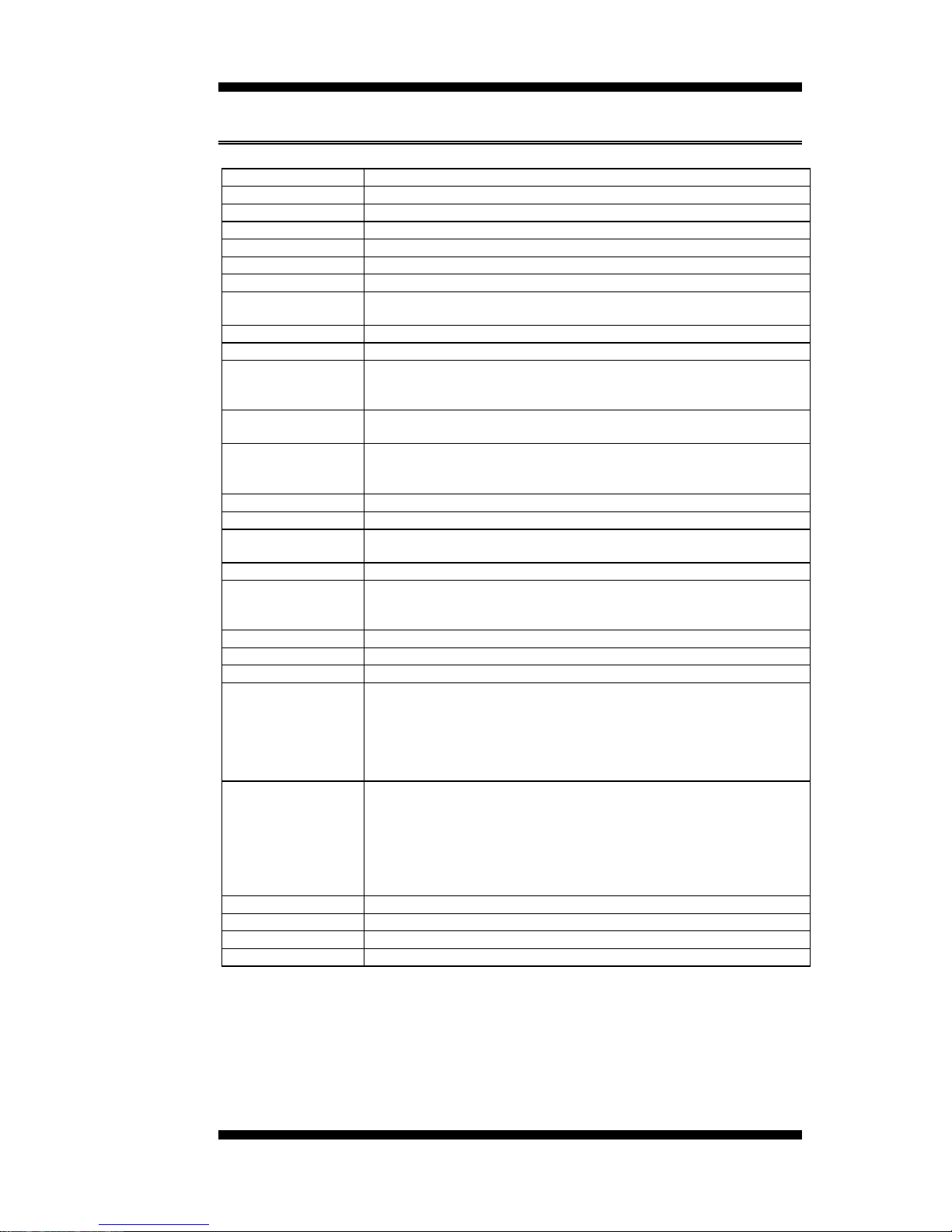
2808220 Specifications
CPU Supported
Intel® Arrandale DC mobile processor
CPU Voltage
0.700V ~ 1 5V (IMVP-6.5)
System Speed
Up to 3.0GHz or above
CPU FSB
1066MHz FSB
Cache
Up to 4MB shared L3 Cache
Green /APM
APM1.2
CPU Socket
rPGA Socket 989
Chipset
Intel Ibex Peak-M (PCH) Chipset
PCH: 25mm x 27mm, 1071-pin FCBGA
BIOS
AMI BIOS, supports ACPI function
Memory
DDR3 800/1066 SoDIMM x2 (w/o ECC function), Max. 8GB
VGA
Arrandale DC mobile processor integrated graphics
Supports CRT
Supports DVI single or Dual
LVDS LCD Panel
Arrandale DC mobile processor built-in, supports 24-bit, single or
dual channel LVDS
LAN
1. PCH 10/100/gigabit MAC + PHY
• Intel 82577LM 10/100/1000
2. Intell 82574L PCI-e Gigabit LAN controller x1 (2808220F)
USB
PCH built-in USB 2.0 host controller, support 10 ports
Serial ATA Ports
PCH built-in SATA controller, supports 4 ports
IAMT6.0
PCH built-in Intel Active Management Technology VER 6 0 with HW
KVM (2808220RF only)
Audio
PCH built-in High Definition audio controller:ALC888 w/ 7.1 channels
LPC I/O
F81865F: COM1, COM2 (RS232/RS422/RS485), COM3 and COM4
Hardware monitor (3 thermal, 4 voltage monitor inputs, 2 fan
headers)
Digital IO
4 in & 4 out
Keyboard/Mouse
Supports PS/2 keyboard/mouse connector
Expansion Slots
PCI slot x1, PIC-E (x1) slot x1 and Mini PCIE socket x1
Edge Connector
PS/2 connector x1 for keyboard/mouse and dual USB stack
connector
Gigabit LAN RJ-45 + dual USB stack connector x2
DVI-D and DVI-I stack connector x1
DB9 x1 for COM 1; DB15 x1 for VGA
RCA Jack 3x1 for Audio (Front-Out, Line-In, Mic)
Onboard Header/
Connector
10-pin headerx1 for Digital I/O; 10-pin header x1 for COM2
20-pin header x1 for COM3, COM4
10-pin header x 2 for USB 7,8; 9,10
DF13 connector x2 for LVDS;
10-pin header x1 for audio Line-Out & Mic
4-pin header x1 for CD in, SPDIF-out connector x1
SATA connector x4 for SATA ports
Watchdog Timer
Yes (256 segments, 0, 1, 2…255 sec/min)
System Voltage
+5V, +3.3V, +12V, -12V, 5VSB (2A)
Others
Modem Wakeup, LAN Wakeup
Board Size
170mm x 170mm (Mini ITX)
INTRODUCTION
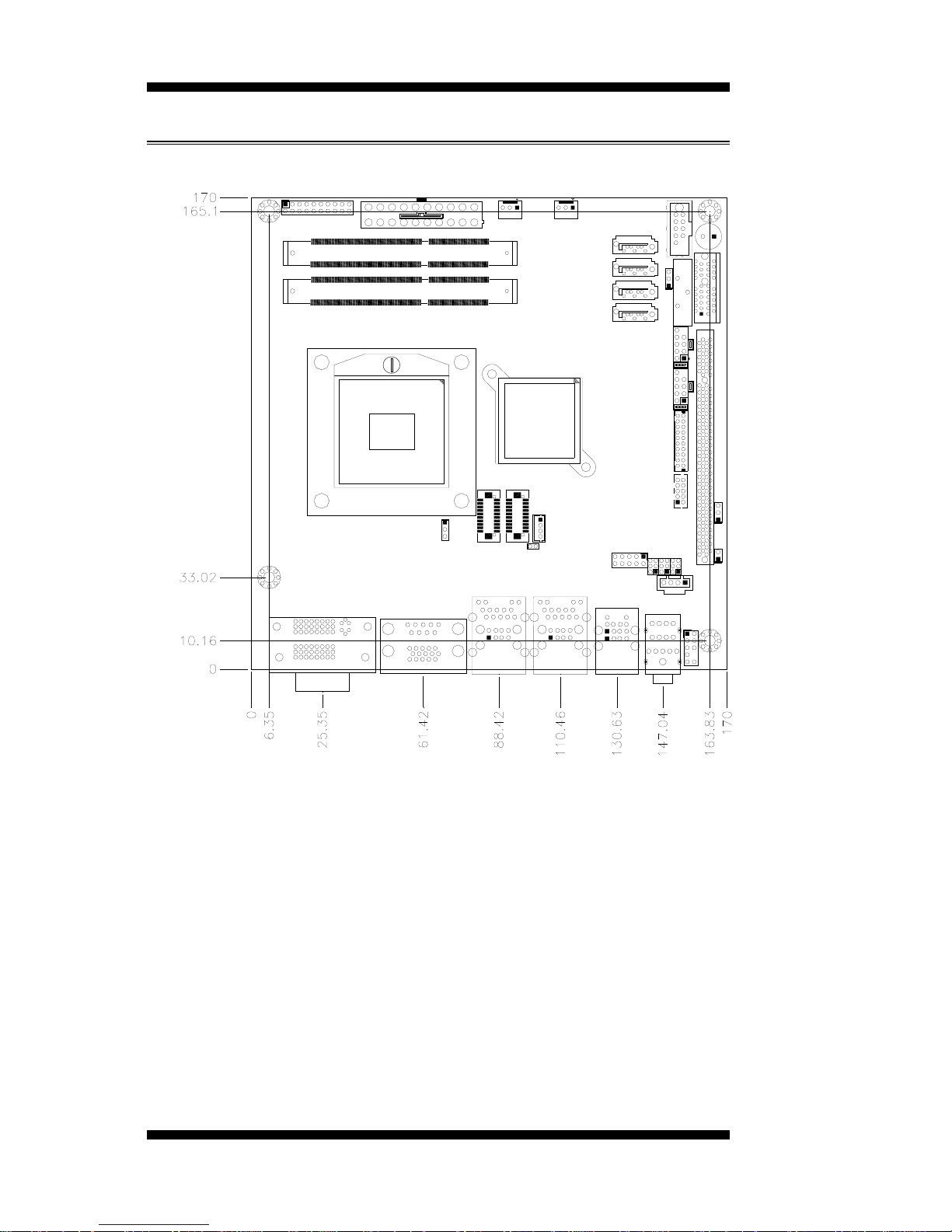
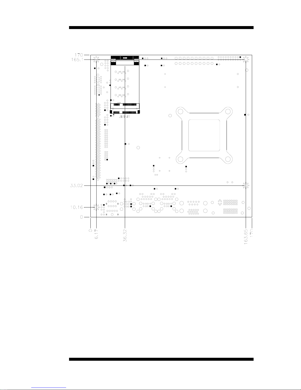
[
Board Dimensions
4
2808220 User’s Manual
INTRODUCTION
2808220 User’s Manual 5

INSTALLATIONS
6
2808220 User’s Manual
Installations
This section provides information on how to use the jumpers and
connectors on the 2808220 in order to set up a workable system. The
topics covered are:
Installing the CPU .................................................................................. 7
Installing the Memory ............................................................................ 8
Setting the Jumpers ................................................................................ 9
Connectors on 2808220 .......................................................................... 13
INSTALLATIONS
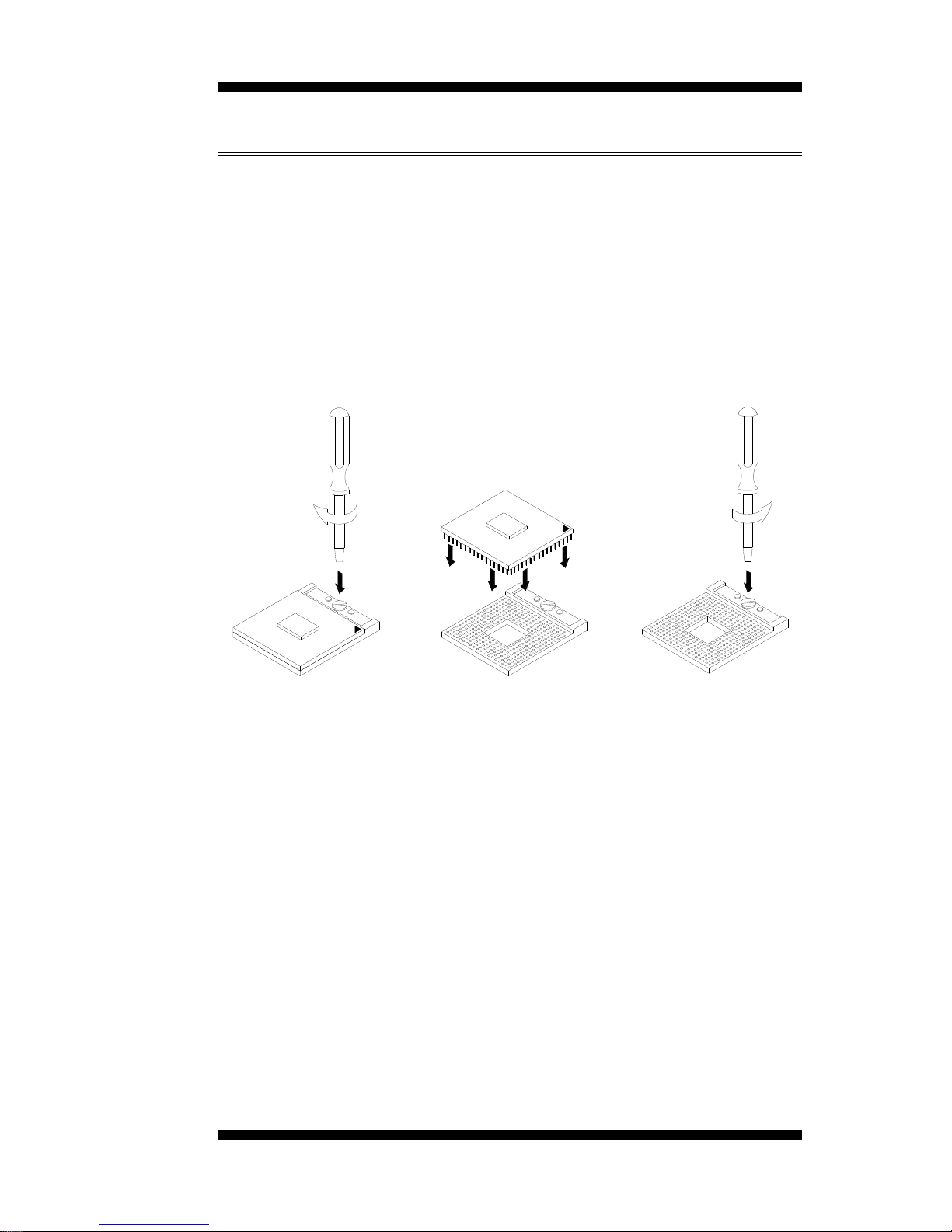
Installing the CPU
The 2808220 board supports rPGA989 socket for Intel® Arrandale Dual
Core mobile processors.
The processor socket comes with a screw to secure the processor. As
shown in the left picture below, loosen the screw first before inserting
the processor. Place the processor into the socket by making sure the
notch on the corner of the CPU corresponds with the notch on the inside
of the socket. Once the processor has slide into the socket, fasten the
screw. Refer to the figures below.
NOTE:
Ensure that the CPU heat sink and the CPU top surface are in
total contact to avoid CPU overheating problem that would
cause your system to hang or be unstable.
2808220 User’s Manual 7

INSTALLATIONS
Installing the Memory
The 2808220 board supports two DDR3 memory socket for a maximum
total memory of 8GB in DDR3 SO-DIMM memory type.
Installing and Removing Memory Modules
To install the DDR3 modules, locate the memory slot on the board and
perform the following steps:
1. Hold the DDR3 module so that the key of the DDR3 module aligned
with that on the memory slot.
2. Gently push the DDR3 module in an upright position until the clips of
the slot close to hold the DDR3 module in place when the DDR3
module touches the bottom of the slot.
3. To remove the DDR3 module, press the clips with both hands.
8
2808220 User’s Manual
DDR3 Module
Lock
Lock Lock
Lock

INSTALLATIONS
2808220 User’s Manual 9
Setting the Jumpers
Jumpers are used on 2808220 to select various settings and features
according to your needs and applications. Contact your supplier if you
have doubts about the best configuration for your needs. The following
lists the connectors on 2808220 and their respective functions.
Jumper Locations on 2808220 ................................................................ 10
JP1: LCD Panel Power Selection ........................................................ 11
JP3, JP4, JP5: RS232/422/485 (COM2) Selection .............................. 11
JP6: PCI/PCIE Riser Card Selection ................................................... 12
JBAT1: Clear CMOS Setting .............................................................. 12
JP8: PS/2 Keyboard/Mouse Power Selection ...................................... 12
IMPORTANT NOTE: When the system boots without the CRT being
connected, there will be no image on screen when you insert the
CRT/VGA cable. To show the image on screen, the hotkey must be
pressed.

INSTALLATIONS
Jumper Locations on 2808220
Jumpers on 2808220 ........................................................................... Page
JP1: LCD Panel Power Selection ......................................................... 11
JP3, JP4, JP5: RS232/422/485 (COM2) Selection .............................. 11
JP6: PCI/PCIE Riser Card Selection .................................................... 12
JBAT1: Clear CMOS Setting............................................................... 12
JP8: PS/2 Keyboard/Mouse Power Selection ...................................... 12
10
2808220 User’s Manual
INSTALLATIONS
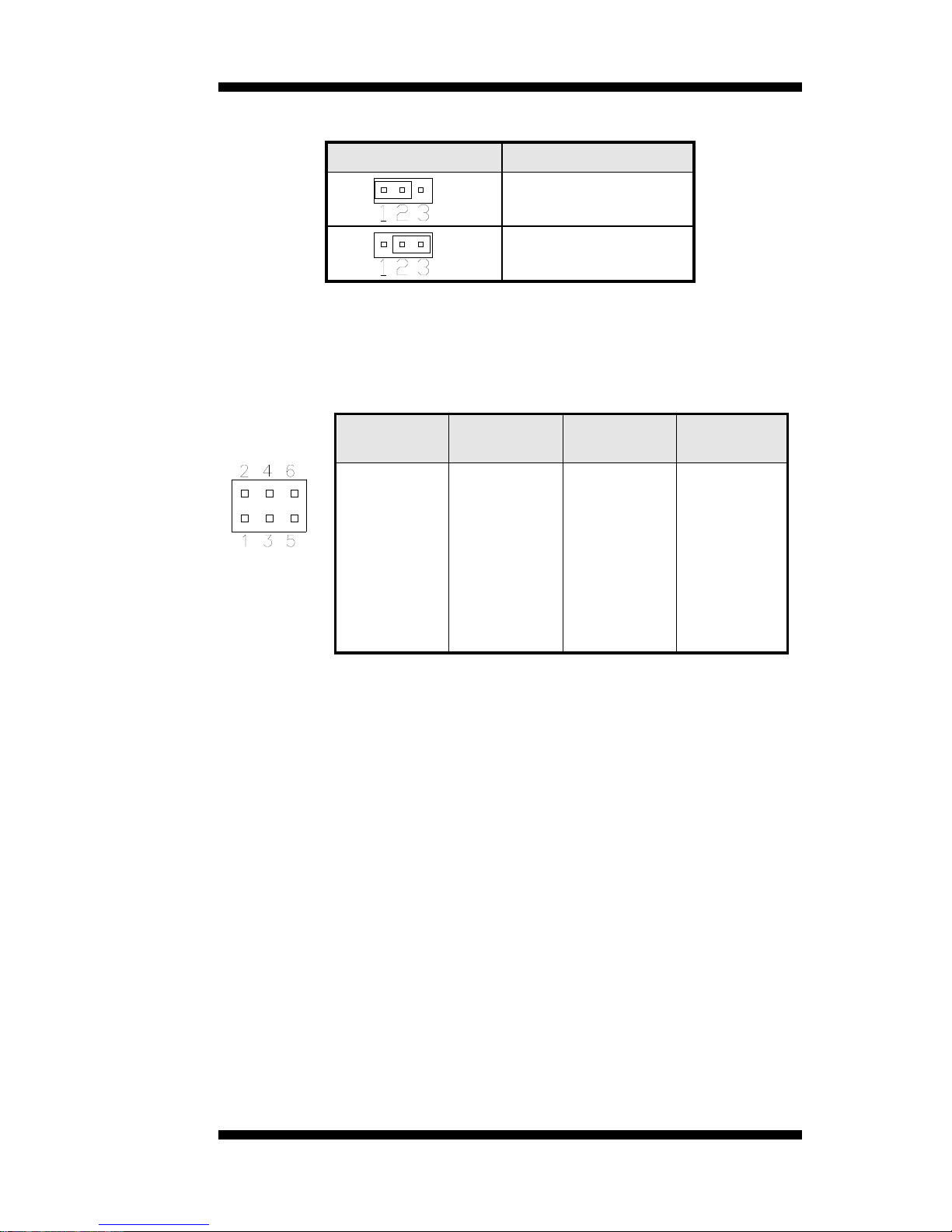
JP1: LCD Panel Power Selection
JP1 LCD Panel Power
3.3V
5V
JP3, JP4, JP5: RS232/422/485 (COM2) Selection
COM1 is fixed for RS-232 use only.
COM2 is selectable for RS232, RS-422 and RS-485.
The following table describes the jumper settings for COM2 selection.
COM2
Function
RS-232 RS-422 RS-485
Jumper
Setting
(pin closed)
JP3:
1-2
JP4:
3-5 & 4-6
JP5:
3-5 & 4-6
JP3:
3-4
JP4:
1-3 & 2-4
JP5:
1-3 & 2-4
JP3:
5-6
JP4:
1-3 & 2-4
JP5:
1-3 & 2-4
2808220 User’s Manual 11
INSTALLATIONS
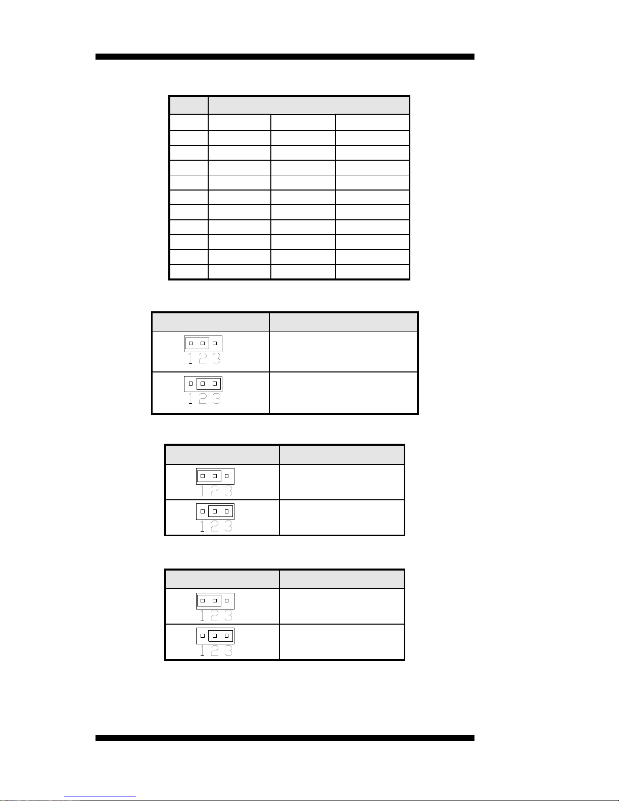
COM2 is jumper selectable for RS-232, RS-422 and RS-485.
Pin # Signal Name
RS-232 R2-422 RS-485
1 DCD TX- DATA2 RX TX+ DATA+
3 TX RX+ NC
4 DTR RX- NC
5 Ground Ground Ground
6 DSR RTS- NC
7 RTS RTS+ NC
8 CTS CTS+ NC
9 RI CTS- NC
10 NC NC NC
JP6: PCI/PCIE Riser Card Selection
JP6 Riser Card
IP390 Riser Card
Install
IP151, IP240 Riser Card
Install
JBAT1: Clear CMOS Setting
JBAT1 Setting
Normal
Clear CMOS
JP8: PS/2 Keyboard/Mouse Power Selection
JP8 KB/MS Power
+5V
5V_DUAL
12
2808220 User’s Manual

INSTALLATIONS
2808220 User’s Manual 13
Connectors on 2808220
Connector Locations on 2808220 ........................................................... 14
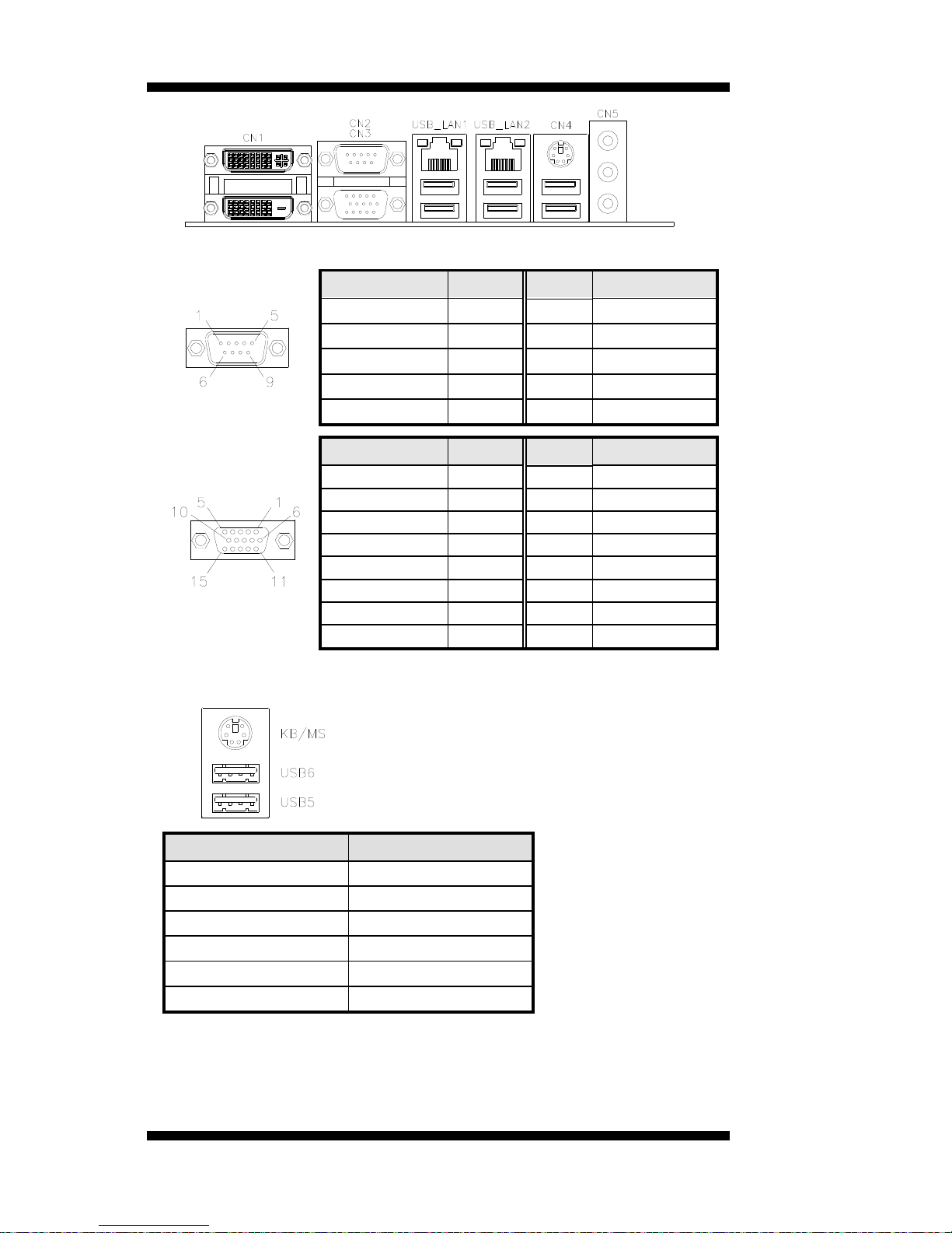
CN1: DVI-D and DVI-I Connector ..................................................... 15
CN2, CN3: COM1 and VGA Connector ............................................. 16
CN4: PS/2 Keyboard/Mouse Connectors and USB5/6 Ports .............. 16
USB_LAN1: 10/100/1000 RJ-45 (2808220F) and USB3/4 Ports .......... 17
USB_LAN2: 10/100/1000 RJ-45 (2808220) and USB1/2 Ports ............ 17
CN5: Audio Connector ........................................................................ 17
COM3_COM4: COM3, COM4 Serial Port ......................................... 17
SYS_FAN1: System Fan Power Connector ........................................ 17
CPU_FAN1: CPU Fan Power Connector ............................................ 17
ATX1: ATX Power Supply Connector ............................................... 18
J1 (F_PANEL): System Function Connector ...................................... 18
F_USB1: USB7/USB8 Connector ....................................................... 20
F_USB2: USB9/USB10 Connector ..................................................... 20
COM2: COM2 Serial Port ................................................................... 20
LVDS1, LVDS2: LVDS Connectors (1st channel, 2nd channel) ....... 21
J2: LCD Backlight Connector ............................................................. 21
J3: Digital I/O ...................................................................................... 21
J4: CD-In Pin Header .......................................................................... 21
J5: SPI Flash Connector (factory use only) ......................................... 22
J6: Front Audio Connector .................................................................. 22
J7: PCI-E(x1) Slot ............................................................................... 22
J8: SPDIF Out Connector .................................................................... 22
PCI1: PCI Slot (supports 2 Master) ..................................................... 22
JMINI: Mini PCIE Connector ............................................................. 22
SATA1, SATA2, SATA3, SATA4: SATA Connectors ...................... 22
INSTALLATIONS
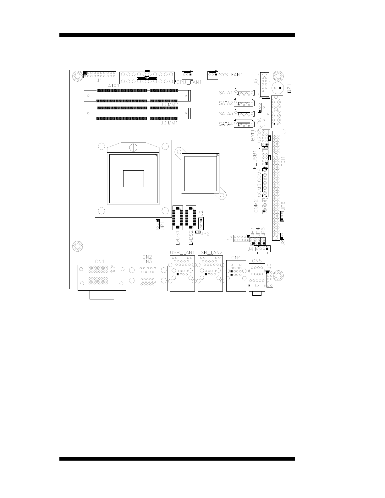
Connector Locations on 2808220
14
2808220 User’s Manual
INSTALLATIONS
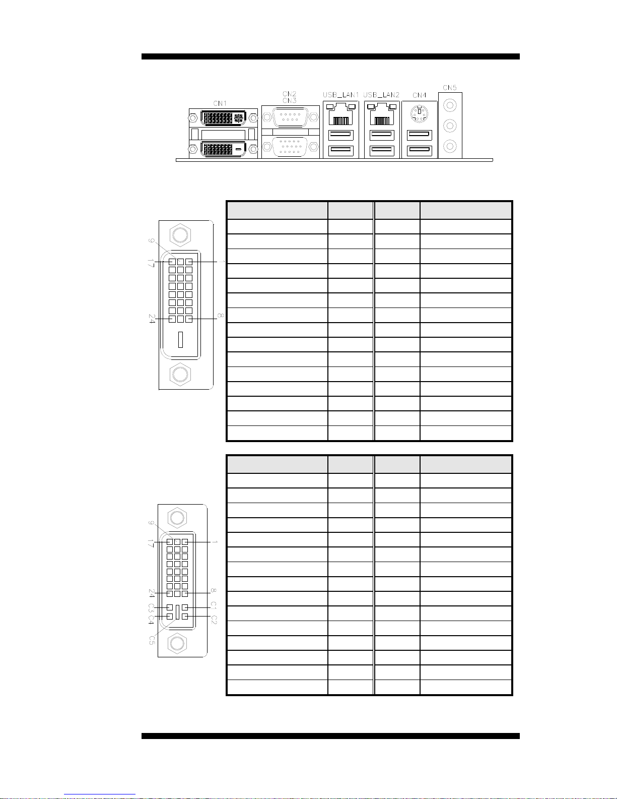
CN1: DVI-D and DVI-I Connector
[
Signal Name Pin # Pin # Signal Name
DATA 2- 1 16 HOT POWER
DATA 2+ 2 17 DATA 0Shield 2/4 3 18 DATA 0+
DATA 4- 4 19 SHIELD 0/5
DATA 4+ 5 20 DATA 5-
DDC CLOCK 6 21 DATA 5+
DDC DATA 7 22 SHIELD CLK
N.C 8 23 CLOCK -
DATA 1- 9 24 CLOCK +
DATA 1+ 10 C1 N.C.
SHIELD 1/3 11 C2 N.C.
DATA 3- 12 C3 N.C.
DATA 3+ 13 C4 N.C.
DDC POWER 14 C5 N.C.
A GROUND 1 15 C6 N.C.
Signal Name Pin # Pin # Signal Name
DATA 2- 1 16 HOT POWER
DATA 2+ 2 17 DATA 0Shield 2/4 3 18 DATA 0+
DATA 4- 4 19 SHIELD 0/5
DATA 4+ 5 20 DATA 5-
DDC CLOCK 6 21 DATA 5+
DDC DATA 7 22 SHIELD CLK
N.C 8 23 CLOCK -
DATA 1- 9 24 CLOCK +
DATA 1+ 10 C1 N.C
SHIELD 1/3 11 C2 N.C
DATA 3- 12 C3 N.C
DATA 3+ 13 C4 N.C
DDC POWER 14 C5 A GROUND2
A GROUND 1 15 C6 A GROUND3
2808220 User’s Manual 15
INSTALLATIONS
16
2808220 User’s Manual
CN2, CN3: COM1 and VGA Connector
[
Signal Name Pin # Pin # Signal Name
DCD 1 6 DSR
RXD 2 7 RTS
TXD 3 8 CTS
DTR 4 9 RI
GND 5 10 Not Used
[[
Signal Name Pin # Pin # Signal Name
Red 1 2 Green
Blue 3 4 N.C.
GND 5 6 GND
GND 7 8 GND
N.C. 9 10 GND
N.C. 11 12 DDC DATA
HSYNC 13 14 VSYNC
DDC_CLK 15
CN4: PS/2 Keyboard/Mouse Connectors and USB5/6 Ports
PS/2 Keyboard & Mouse
USB Port5 /Port6
Signal Name Keyboard/Mouse
Keyboard data 1
Mouse data 2
GND 3
5V 4
Keyboard clock 5
Mouse clock 6
INSTALLATIONS
USB_LAN1: 10/100/1000 RJ-45 (2808220F) and USB3/4 Ports
USB_LAN2: 10/100/1000 RJ-45 (2808220) and USB1/2 Ports
CN5: Audio Connector
The audio connector, from top to bottom, is composed of Line in, Line
out and Microphone jacks.
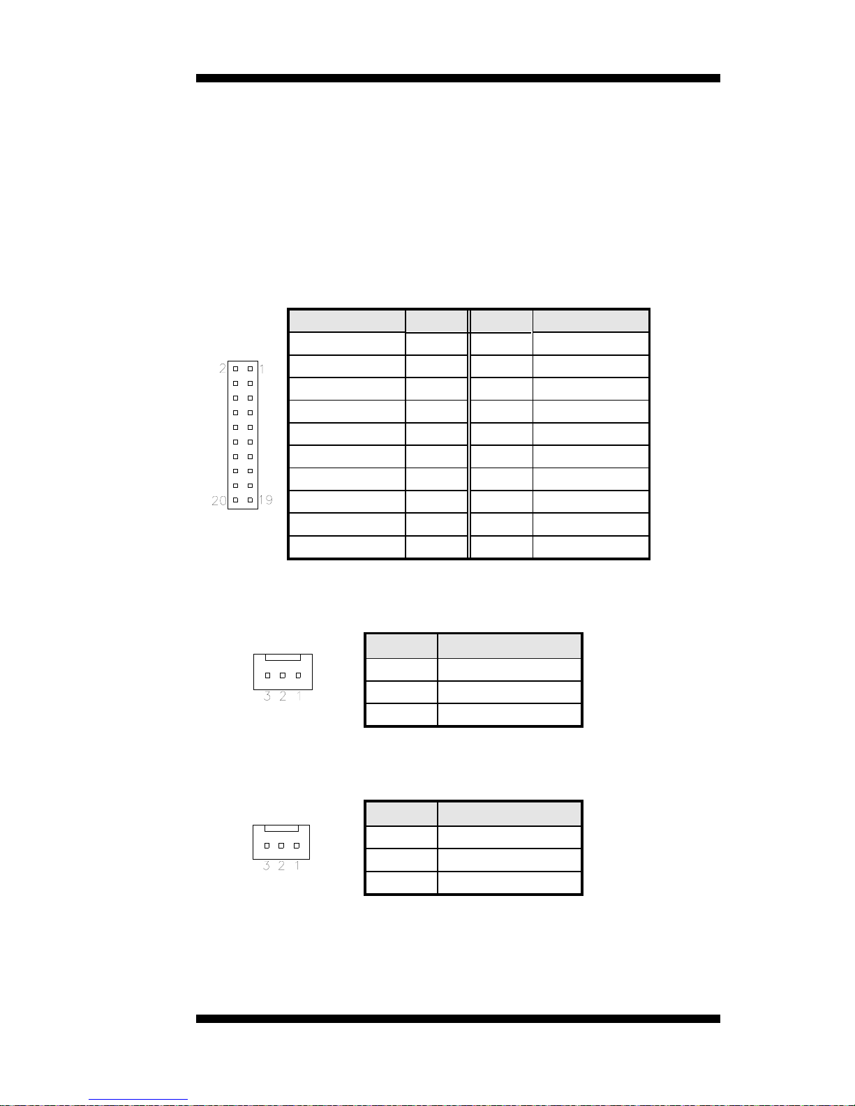
COM3_COM4: COM3, COM4 Serial Port
Signal Name Pin # Pin # Signal Name
DSR 2 1 DCD
RTS 4 3 RXD
CTS 6 5 TXD
RI 8 7 DTR
NA 10 9 Ground
DSR 12 11 DCD
RTS 14 13 RXD
CTS 16 15 TXD
RI 18 17 DTR
NA 20 19 Ground
SYS_FAN1: System Fan Power Connector
This is a 3-pin header for system fans. The fan must be a 12V (500mA).
Pin # Signal Name
1 Ground
2 +12V
3 Rotation detection
CPU_FAN1: CPU Fan Power Connector
This is a 3-pin header for the CPU fan. The fan must be a 12V fan.
Pin # Signal Name
1 Ground
2 +12V
3 Rotation detection
2808220 User’s Manual 17
INSTALLATIONS
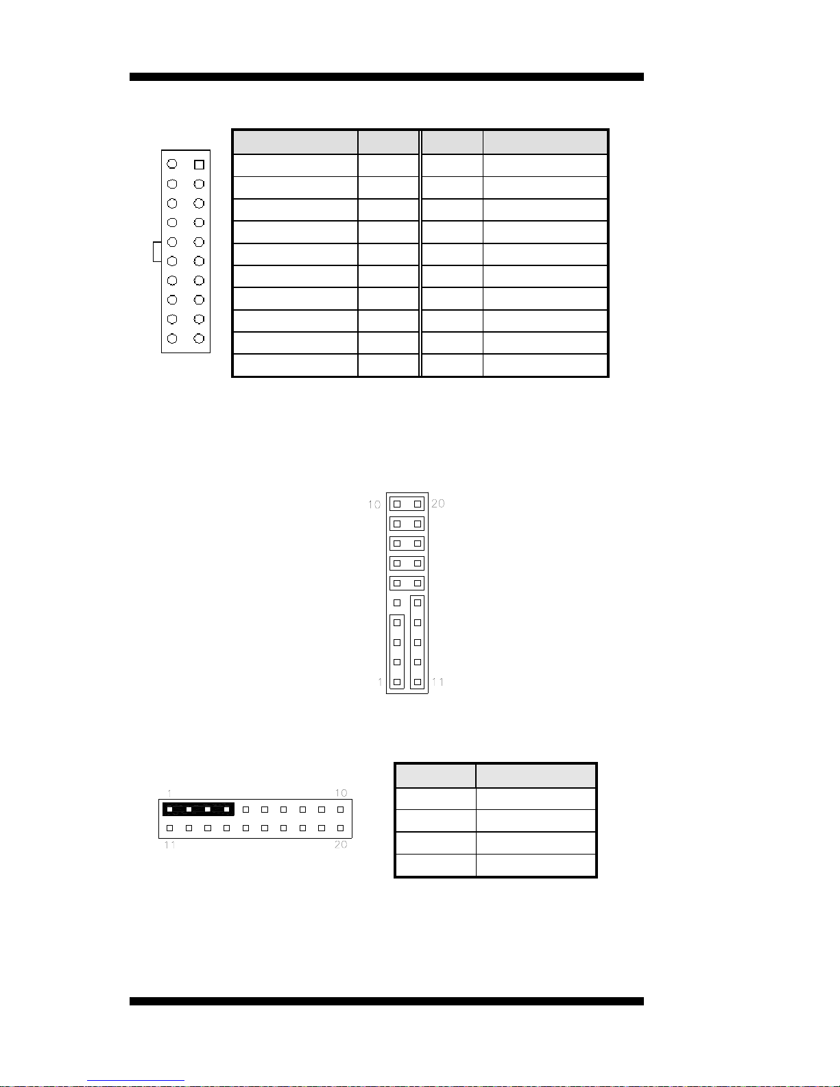
ATX1: ATX Power Supply Connector
11 1
20 10
Signal Name Pin # Pin # Signal Name
3.3V 11 1 3.3V
-12V 12 2 3.3V
Ground 13 3 Ground
PS-ON 14 4 +5V
Ground 15 5 Ground
Ground 16 6 +5V
Ground 17 7 Ground
-5V 18 8 Power good
+5V 19 9 5VSB
+5V 20 10 +12V
J1 (F_PANEL): System Function Connector
J1 provides connectors for system indicators that provide light indication
of the computer activities and switches to change the computer status. J2
is a 20-pin header that provides interfaces for the following functions.
Hard Disk Drive LED
Reset Switch
Not Defined
ATX Power On Switch
Not Defined
Power LED
Speaker
Speaker: Pins 1 - 4
This connector provides an interface to a speaker for audio
tone generation. An 8-ohm speaker is recommended.
Pin # Signal Name
1 Speaker out
2 No connect
3 Ground
4 +5V
18
2808220 User’s Manual
 Loading...