

Global American 2808120 User Manual

2808120 User’s Manual
Version 1.0
Mini-ITX Motherboard with Intel Atom N230

ii
Copyrights
This document is copyrighted and all rights are reserved. It does not allow any non
authorization in copied, photocopied, translated or reproduced to any electronic or
machine readable form in whole or in part without prior written consent from the
manufacturer.
In general, the manufacturer will not be liable for any direct, indirect, special, incidental
or consequential damages arising from the use of inability to use the product or
documentation, even if advised of the possibility of such damages. The manufacturer
keeps the rights in the subject to change the contents of this document without prior
notices in order to improve the function design, performance, quality and reliability. The
author assumes no responsibility for any errors or omissions, which may appear in this
document, nor does it make a commitment to update the information contained herein.
Trademarks
Intel is a registered trademark of Intel Corporation.
Award is a registered trademark of Award Software, Inc.
All other trademarks, products and or product's name mentioned herein are mentioned
for identification purposes only, and may be trademarks and/or registered trademarks of
their respective companies or owners.

Table of Contents
Introduction ....................................................... 1
Product Description ............................................................. 1
Checklist .............................................................................. 1
2808120 Specifications ....................................................... 2
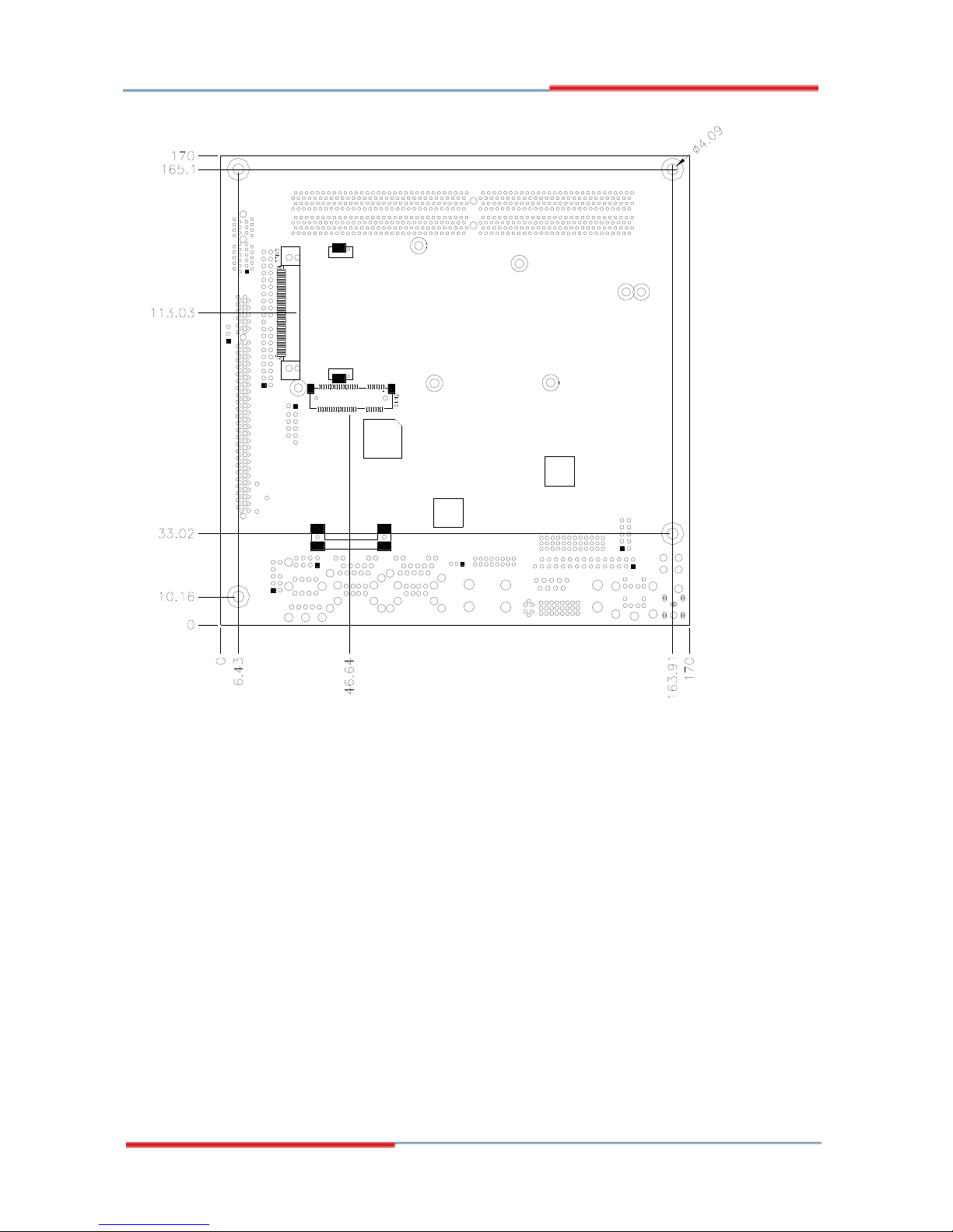
Board Dimensions ............................................................... 3
Installations ....................................................... 5
Installing the Memory ......................................................... 6
Setting the Jumpers ............................................................. 7
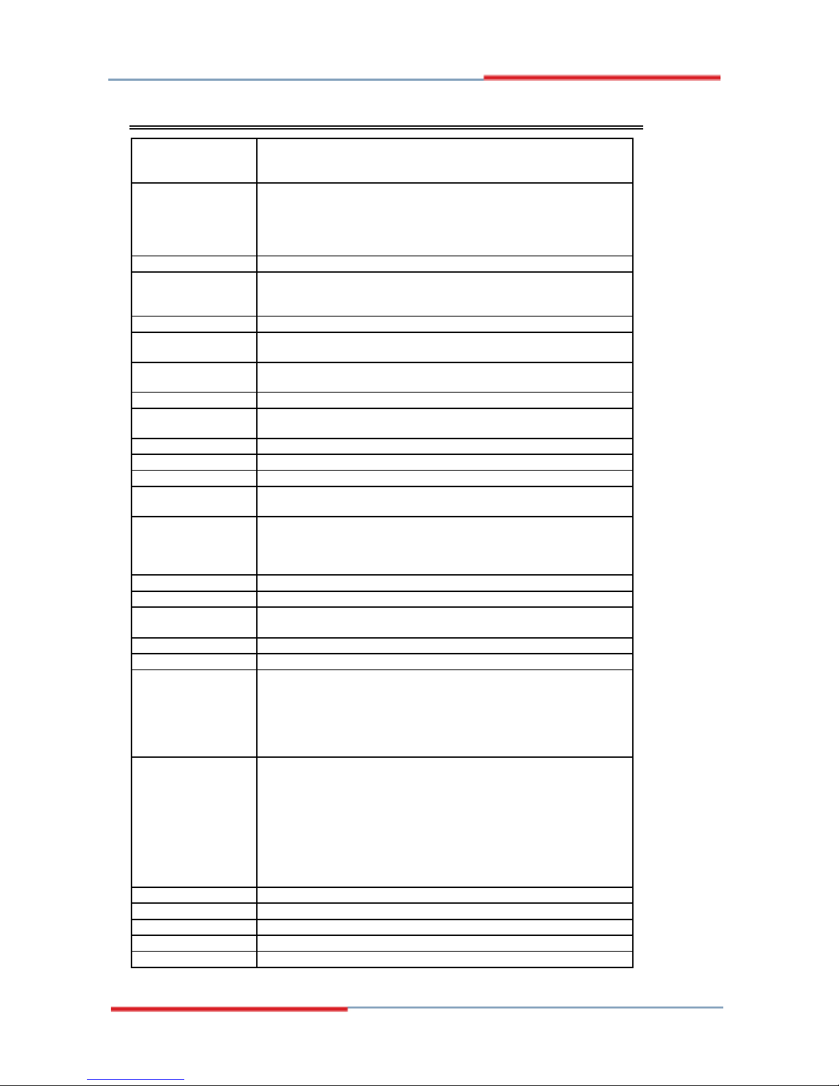
Connectors on 2808120 ..................................................... 12
BIOS Setup ....................................................... 23
Appendix ........................................................... 57
A. I/O Port Address Map ................................................... 57
B. Interrupt Request Lines (IRQ) ...................................... 58
C. Watchdog Timer Configuration .................................... 59
iii

iv
This p
age is intentionally left blank.

1
Introduction
Product Description
The 2808120 Mini ITX board incorporates the Intel® 945GC Express Chipset for
Embedded Computing comes built in with the Intel® GMA950 graphics. The
new Intel® Graphics Media Accelerator 950 (Intel® GMA 950) graphics core is
an intelligent and responsive graphics engine built into the chipset that is on the
motherboard. This integration provides incredible visual quality, faster graphics
performance and flexible display options without the need for a separate
graphics card.
The main features of the 2808120 Mini ITX Motherboard are:
Supports Intel Atom 230 processor with 1.6GHz speed
Two DDRII SDRAM DIMM supports up to 2GB of DDR2
400/533MHz memory
Onboard 10/100 BaseT and Intel 82574L PCI-Express Gigabit LAN
Intel® 945GC VGA for CRT, SDVO port supports LVDS and DVI
2x SATA, 6x USB 2.0, 4x COM, Watchdog timer
1x PCI, 1x MiniPCIe, CF socket, DC-in for +12V/+19V input
Dimensions of the board are 170mm x 170mm.
Ordering Information:
2808120: Intel Atom, 1.6GHz, 945GC chipset with DVI, LVDS, 1x
10/100 LAN, 1x Gigabit LAN, Mini PCI-E, PCI
Checklist
Your 2808120 package should include the items listed below.
• The 2808120 Intel® Atom Mini-ITX motherboard
• This User’s Manual
• 1 CD containing chipset drivers and flash memory utility
• Cable kit (IDE, 2x Serial port, Serial ATA)
2 2808120 User’s Manual
2808120 Specifications
CPU Type
Intel New architecture CPU on 45nm processor
- Atom 230 (Diamondville Single Core)
- Atom 330 (Diamondville Dual Core)
CPU FSB
CPU Clock speed = 1.60GHz
FSB=533MHz
L2 Cache=512K for SC / 1M for DC
Cores/Treads=1/2 threads.
TDP=4W for SC / 8W for DC
CPU Socket
473 pins micro-FCBGA on board
Chipset
Intel 945GC Chipset
GMCH: 82945GC 34 mm x 34 mm -1202 balls FCBGA
ICH7: 82801GH: 31mm x 31mm -652-pin BGA
BIOS
Award BIOS, support ACPI Function
Memory
DDRII 400/533 DIMM x 2 (w/o ECC function), supports Dual
channel. Max. 2GB
VGA
The 82945GC GMCH provides an integrated graphics device
(IGD) delivering cost competitive 3D, 2D, and video capabilities.
DVI + LVDS
Chrontel CH7307 + Chrontel CH7308C
LAN
1. ICH7 built-in 10/100BT MAC + Intel 82562ET PHY
2. Intel 82574L PCI Express Gigabit LAN controller x1
USB
ICH7 built-in USB 2.0 host controller, support 6 ports
Serial ATA
ICH7 built-in SATA controller, supports 2 ports
Parallel IDE
ICH7 built-in one channel Ultra DMA 33/66/100, CF
Audio
ICH7 built -in Audio controller ALC 662 5.1-Channel (Line-in,
Line-out & MIC)
LPC I/O
Winbond W83627EHG: COM1 (RS232), COM2
(RS232/422/485),
Hardware monitor (3 thermal inputs, 4 voltage monitor inputs,
VID0-4 & 2 Fan Headers)
2’nd LPC I/O
Fintek F81216DG COM3 & COM4 (RS232)
Digital IO
4 in & 4 out
Keyboard/Mouse
Connector
Supports PS/2 Keyboard/Mouse
Expansion
PCI slot x1, PCI-E (x1) slot x1 and Mini PCI-E (x1) socket x1
Power Connector
DC Power jack x1 for +12V/+19V DC-in
Edge Connector
PS/2 Connector x1 for keyboard/mouse
Gigabit LAN RJ-45 + dual USB stack connector
10/100 LAN RJ45 + dual USB stack connector
VGA+DVI-D stack connector
3x1 stack mini jacks (0.125”) for HD audio (Line-in, Line-Out, Mic)
DC-IN jack
On Board Header/
Connector
40 pins box-header x1 for IDE1
CF Connector x1 @ solder side
10 pins pin-headerx1 for Digital I/O
20 pins DF11 connector x2 for COM1/COM2, COM3/COM4 (Pin 9
can be powered with 5V or 12V or as ring-in)
8 pins pin-header x 1 for USB 5,6
10 pins pin-header x1 for audio Line-Out & Mic
SATA connector x2 for 2 SATA ports
DF13 Connector x2 for LVDS
Watchdog Timer
Yes (256 segments, 0, 1, 2…255 sec/min)
Other
Modem Wakeup, LAN Wakeup
RoHS
Yes
Form Factor4
Mini ITX
Board Size
170mm x 170mm
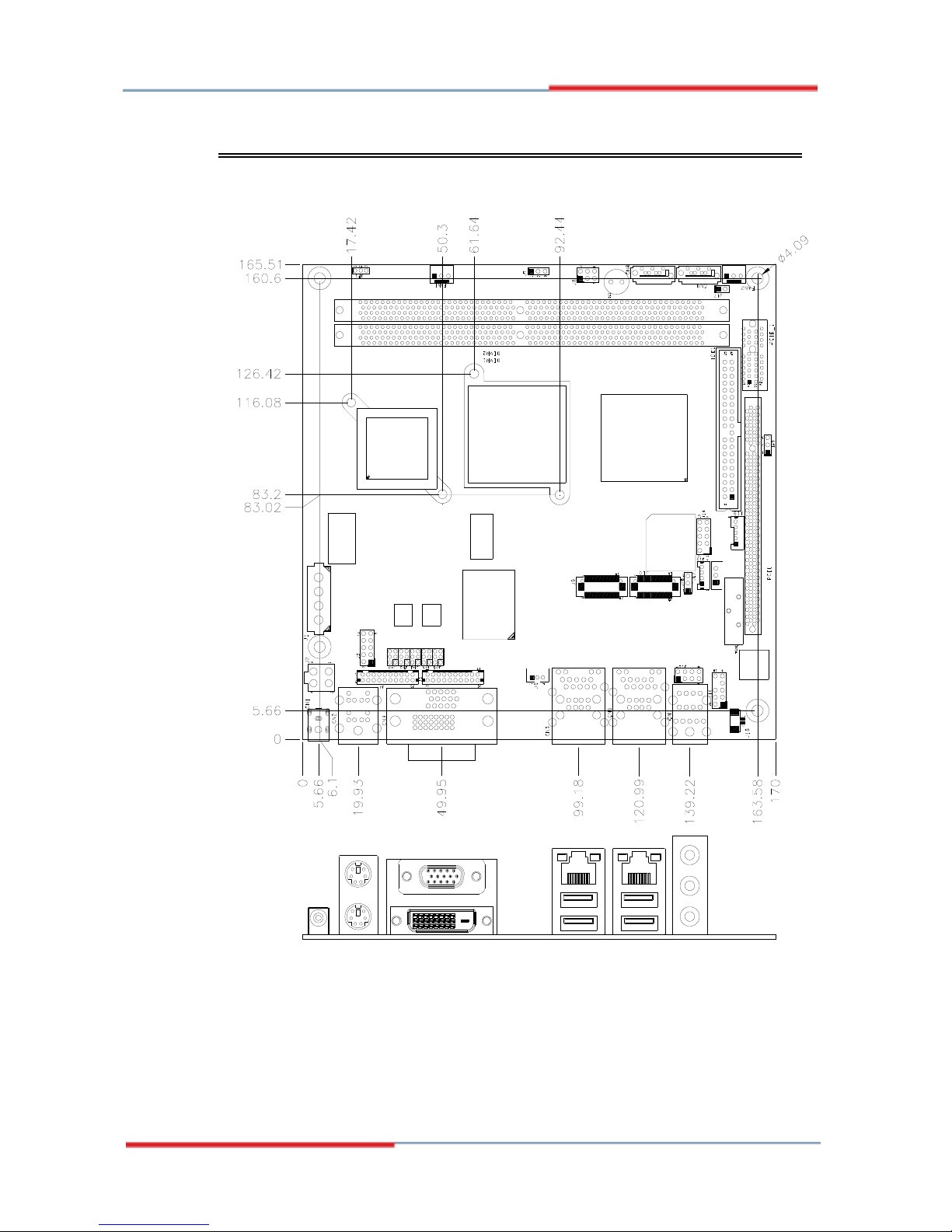
Board Dimensions
2808120 User’s Manual 3
4 2808120 User’s Manual

2808120 User’s Manual 5
Installations
This section provides information on how to use the jumpers and
connectors on the 2808120 in order to set up a workable system. The
topics covered are:
Installing the Memory ........................................................................... 6
Setting the Jumpers ................................................................................ 7
Connectors on 2808120 .......................................................................... 12
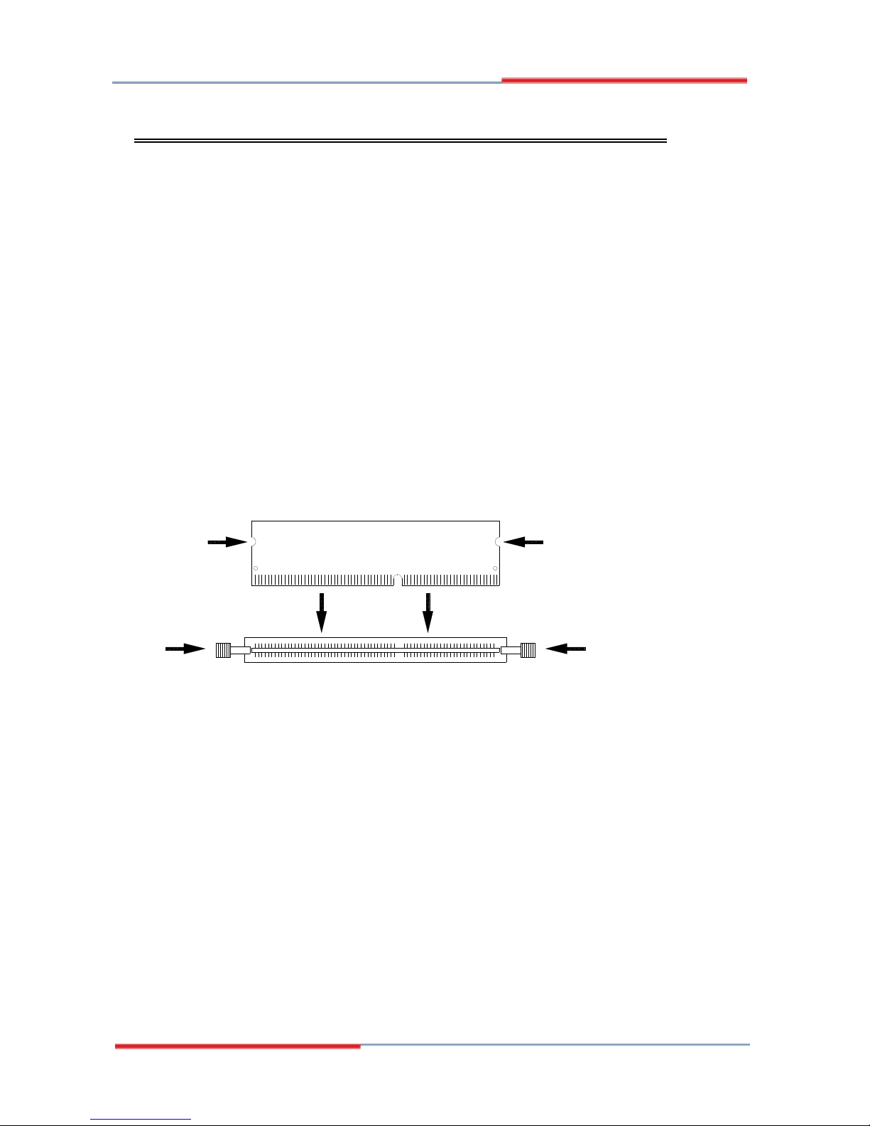
Installing the Memory
The 2808120 board supports two DDR2 memory socket for a maximum
total memory of 2GB in DDR2 memory type.
Installing and Removing Memory Modules
To install the DDR2 modules, locate the memory slot on the board and
perform the following steps:
1. Hold the DDR2 module so that the key of the DDR2 module align
with those on the memory slot.
2. Gently push the DDR2 module in an upright position until the clips of
the slot close to hold the DDR2 module in place when the DDR2
module touches the bottom of the slot.
3. To remove the DDR2 module, press the clips with both hands.
DDR2 Module
Lock Lock
Lock Lock
6 2808120 User’s Manual

2808120 User’s Manual 7
Setting the Jumpers
Jumpers are used on 2808120 to select various settings and features
according to your needs and applications. Contact your supplier if you
have doubts about the best configuration for your needs. The following
lists the connectors on 2808120 and their respective functions.
Jumper Locations on 2808120 .................................................................. 8
JP1: ATX/AT Mode Select.................................................................... 9
JP2, JP3, JP4: RS232/422/485 (COM2) Selection ................................ 9
JP5: COM4 RS232 +5V / +12V Power Setting .................................. 10
JP6: COM3 RS232 +5V / +12V Power Setting .................................. 10
JP8: LCD Panel Power Selection ........................................................ 10
JP9: Clear CMOS Setting .................................................................... 10
J17: CompactFlash Slave/Master Selection ......................................... 11
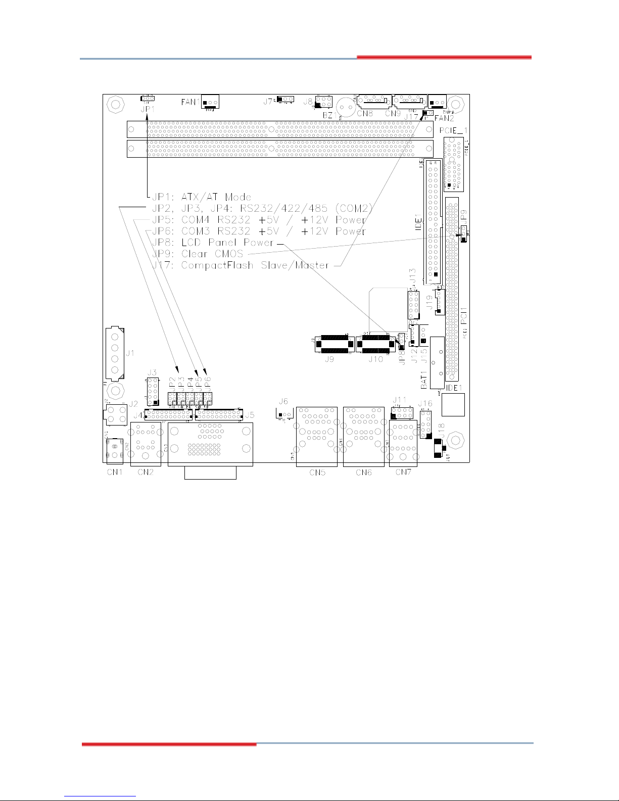
Jumper Locations on 2808120
Jumpers on 2808120 ........................................................................... Page
JP1: ATX/AT Mode Select .................................................................... 9
JP2, JP3, JP4: RS232/422/485 (COM2) Selection ................................ 9
JP5: COM4 RS232 +5V / +12V Power Setting ................................... 10
JP6: COM3 RS232 +5V / +12V Power Setting ................................... 10
JP8: LCD Panel Power Selection ......................................................... 10
JP9: Clear CMOS Setting .................................................................... 10
J17: CompactFlash Slave/Master Selection ......................................... 11
8 2808120 User’s Manual
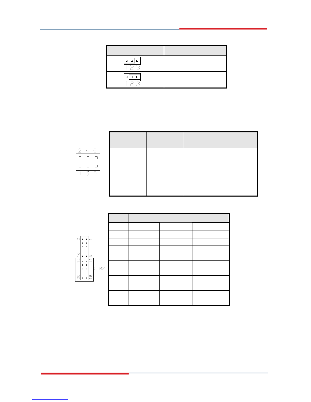
JP1: ATX/AT Mode Select
JP1 ATX / AT
ATX mode
AT mode
JP2, JP3, JP4: RS232/422/485 (COM2) Selection
COM1/3/4 is fixed for RS-232 use only.
COM2 is selectable for RS232, RS-422 and RS-485.
The following table describes the jumper settings for COM2 selection.
COM2
Function
RS-232 RS-422 RS-485
Jumper
Setting
(pin closed)
JP4:
1-2
JP3:
3-5 & 4-6
JP2:
3-5 & 4-6
JP4:
3-4
JP3:
1-3 & 2-4
JP2:
1-3 & 2-4
JP4:
5-6
JP3:
1-3 & 2-4
JP2:
1-3 & 2-4
COM2 is jumper selectable for RS-232, RS-422 and RS-485.
Pin # Signal Name
RS-232 R2-422 RS-485
11 DCD TX- DATA13 RX TX+ DATA+
15 TX RX+ NC
17 DTR RX- NC
19 Ground Ground Ground
12 DSR RTS- NC
14 RTS RTS+ NC
16 CTS CTS+ NC
18 RI CTS- NC
20 NC NC NC
2808120 User’s Manual 9
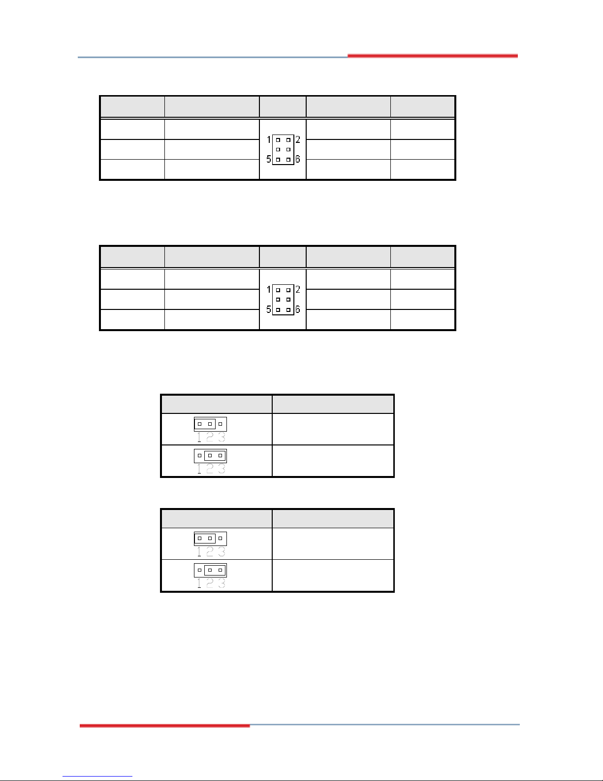
JP5: COM4 RS232 +5V / +12V Power Setting
Pin #
Signal Name JP5 Signal Name
Pin #
1 RI +12V 2
3 RI (Default) RI (Default) 4
5 RI +5V 6
COM4 Settings: Pin 1-2 short = +12V, Pin 5-6 short = +5V, Pin 3-4
Standard COM Port
JP6: COM3 RS232 +5V / +12V Power Setting
Pin #
Signal Name JP6 Signal Name
Pin #
1 RI +12V 2
3 RI (Default) RI (Default) 4
5 RI +5V 6
COM3 Settings: Pin 1-2 short = +12V, Pin 5-6 short = +5V, Pin 3-4
Standard COM Port
JP8: LCD Panel Power Selection
JP8 LCD Panel Power
3.3V
5V
JP9: Clear CMOS Setting
JP9 Setting
Normal
Clear CMOS
10 2808120 User’s Manual
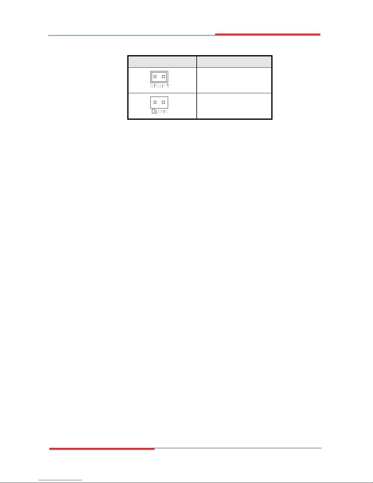
J17: CompactFlash Slave/Master Selection
J17 CF Setting
Master
Slave
2808120 User’s Manual 11

12 2808120 User’s Manual
Connectors on 2808120
The connectors on 2808120 allows you to connect external devices such as
keyboard, floppy disk drives, hard disk drives, printers, etc. The
following table lists the connectors on 2808120 and their respective
functions.
Connector Locations on 2808120 ........................................................... 13
FAN1: CPU Fan Power Connector ...................................................... 15
FAN2: System Fan Power Connector .................................................. 15
CN1: DC Jack (DC in, 12V or 19V) .................................................... 15
CN2: PS/2 Keyboard and PS/2 Mouse Connectors ............................. 15
CN3: VGA and DVI Connector........................................................... 16
CN5: 10/100 RJ-45 and USB1/2 Ports ................................................ 16
CN6: GbE RJ-45 and USB3/4 Ports .................................................... 16
CN7: Audio Connector ........................................................................ 16
CN8, CN9: Serial ATA Connectors .................................................... 16
CN10: Mini PCI- E(x1) Connector (bottom side) ............................... 16
CN11: Compact Flash Connector (bottom side) ................................. 16
PCI1: PCI Slot (supports 2 Master) ..................................................... 16
IDE1: IDE Connector .......................................................................... 17
J1: HDD Power Connector (Output: Max. 2A) ................................... 17
J2: ATX_12V Connector ..................................................................... 17
J3: Digital I/O ...................................................................................... 18
J4: COM1, COM2 Serial Ports ............................................................ 18
J5: COM3, COM4 Serial Ports .......................... 錯誤! 尚未定義書籤。
J6: Wake On LAN Connector .............................................................. 19
J7: Power LED Connector ................................................................... 19
J8: System Function Connector ........................................................... 19
J9, J10: LVDS Connectors (1st channel, 2nd channel) ....................... 19
J11: USB5/6 Port Pin Header .............................................................. 20
J12, J15: LCD Backlight Connector .................................................... 20
J13: SPI Debug Tools Port (Factory use only) .................................... 20
J16: Audio Front Header ..................................................................... 20
J18: SPDIF Out Connector .................................................................. 20
J19: Smart Battery Connector .............................................................. 21
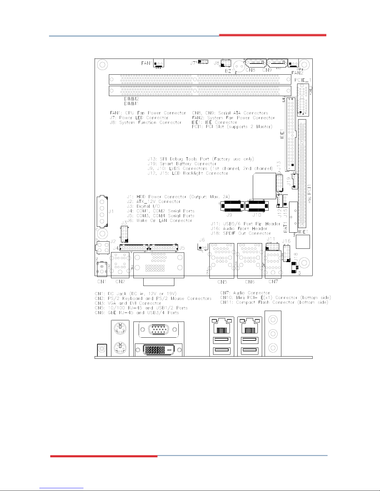
Connector Locations on 2808120
2808120 User’s Manual 13
 Loading...