

Global American 2808060 User Manual

User’s Manual
2808060 Mini-ITX Mainboard
Versi
on
1.0,
October 2008

Copyrights
This manual is cop
yrighted and all rights are reserved. It does not allow any
non authorization in copied, photocopied, translated or reproduced to any
elec
tronic or machine readable form in whole or in part without prior written
consent from the manufacturer.
In general, the manufacturer will not be liable for any direct, indirect, special,
incidental or consequential damages arising from the use of inability to use
the product or documentation, even if advised of the possibility of such
damages. The manufacturer keeps the rights in the subject to change the
contents of this manual without prior notices in order to improve the function
design, performance, quality and reliability. The author assumes no
responsibility for any errors or omissions, which may appear in this manual,
nor does it make a commitment to update the information contained herein.
Trademarks
Intel is a registered trademark of Intel Corporation.
Award is a registered trademark of Award Software, Inc.
All other trademarks, products and or product's name mentioned herein are
mentioned for identification purposes only, and may be trademarks and/or
registered trademarks of their respective companies or owners.

CONTENTS
Chapter 1 Product Overview ................................................................................ 1-1
Mainboard Specifications ................................................................................... 1-2
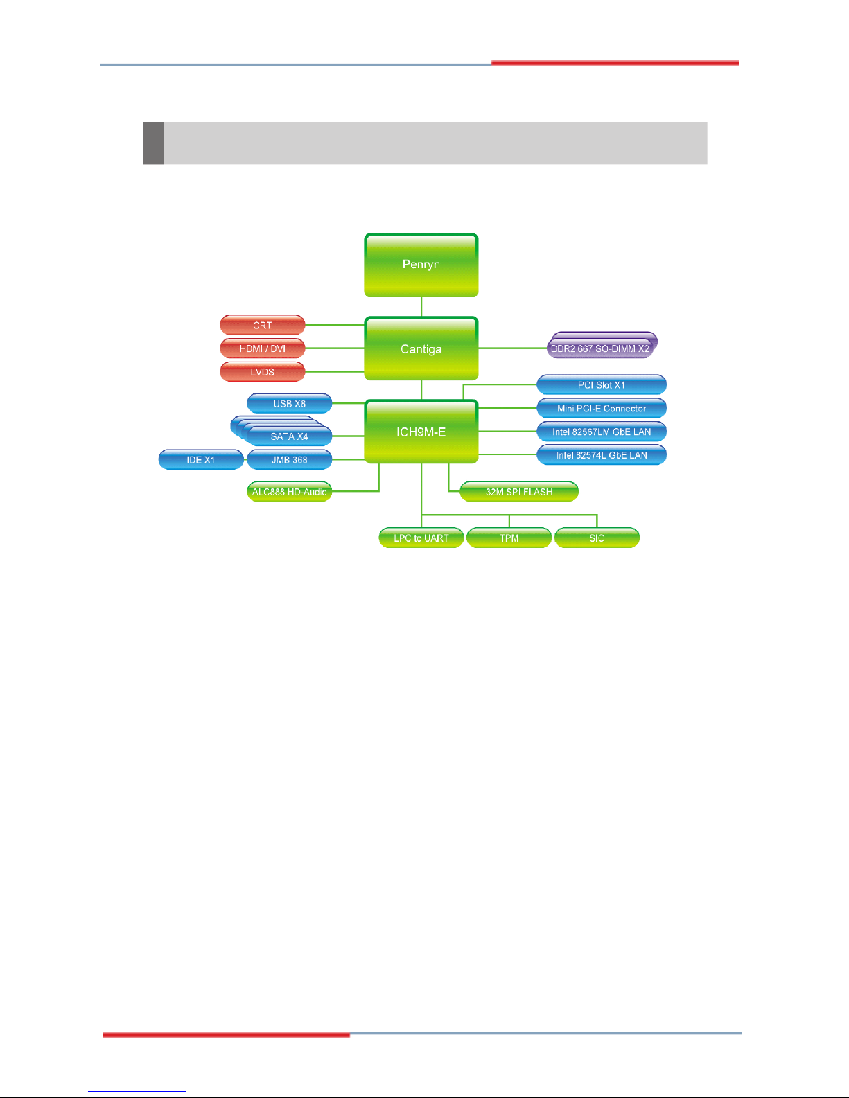
Block Diagram ....................................................................................................... 1-4
Mainboard Layout ................................................................................................ 1-5
Board Dimension .................................................................................................. 1-6
Back Panel & I/O Shield Drawing ........................................................................ 1-7
Power Consumption ............................................................................................ 1-8
Safety Compliance & MTBF ................................................................................ 1-9
Chapter 2 Hardware Setup .................................................................................... 2-1
Quick Components Guide .................................................................................... 2-2
Memory ................................................................................................................. 2-3
CPU (Central Processing Unit) ............................................................................ 2-4
Power Supply ...................................................................................................... 2-6
Back Panel............................................................................................................ 2-7
Connector ............................................................................................................ 2-9
Jumper ................................................................................................................ 2-16
Slot ...................................................................................................................... 2-17
Chapter 3 BIOS Setup ............................................................................................. 3-1
En
tering Setup .....................................................................................................
The Menu Bar ...................................................................................................... 3-4
Main ...................................................................................................................... 3-5
Advanced ............................................................................................................ 3-6
Boot .................................................................................................................... 3-19
Security .............................................................................................................. 3-21
Chipset ............................................................................................................... 3-22
Exit ...................................................................................................................... 3-26
Chapter 4 System Resources ............................................................................. 4-1
Watch Dog Timer Setting ..................................................................................... 4-2
AMI POST Code ................................................................................................... 4-3
Resource List ...................................................................................................... 4-7
3-2
viii

Product Overview
Chapter 1
Product Overview
Thank you for choosing the 2808060
Mini ITX mainboard from Global American Inc.
Based on the innovative Intel® GM45 & ICH9M-E controllers for optimal system efficiency, the 2808060 accommodates the latest Intel® Penryn/Core 2 Duo/
Celeron M processors and supports two DDR2 667/
800MHz SO-DIMM slots to provide the maximum of 4GB
memory capacity.
In the entry-level and mid-range market segment, the
2808060 can provide a high-performance solution for
today’s front-end and general purpose workstation, as
well as in the future.
1-1
2808060 Mainboard
Mainboard Specifications
Processor
- Intel Penryn/Core 2 Duo/Celeron M CPU
- Supports 4-pin CPU fan pin-header with Fan Speed Control
- Supports Intel Dual Core Technology to 667/800/1066MHz and up
FSB
- 667/800/1066MHz
Chipset
- North Bridge: Intel GM45 chipset
- South Bridge: Intel ICH9M-E chipset
Memory
- Unbuffer Non-ECC DDR2 667/800 SDRAM (4GB Max)
- 2 DDR2 SO-DIMM slots (200-pin / 1.8V)
LAN
- Supports Gigabit Ethernet by Intel 82567LM & 82574L
Audio
- HDA Codec by Realtek ALC888 7.1 channel
- Compliant with Azalia 1.0 specs
- 6 watt amplifier
IDE
- 1 IDE port by JMicron JMB368
- Supports Ultra DMA 66/100 mode
- Supports PIO, Bus Master operation mode
CF (Optional)
- 1 CF Type II socket (Master) by JMicron JMB368
SATA
- 4 SATA II ports by ICH9M-E
- Supports storage and data transfers at up to 3Gb/s
- ICH9M-E supports RAID 0, 1
1-2
Connectors
Back Panel
- 1 PS/2 mouse port
- 1 PS/2 keyboard port
- 1 RS-232/422/485 serial port
- 1 HDMI port
- 1 D-Sub VGA port
- 1 DVI port
- 2 RJ-45 LAN jacks
- 4 USB 2.0 ports
- 3 audio jacks
Onboard Connectors
- 1 front panel audio pinheader
- 2 USB 2.0 pinheaders (4 ports)
- 4 RS-232 serial port connectors
- 1 SPI Flash ROM pinheader (for debugging)
- 1 S/PDIF-out pinheader
- 1 LVDS connector
- 1 amplifier connector
Product Overview
Slots
- 1 Mini PCI-E slot
- 1 PCI Express x1 slot
- 1 32-bit/33MHz PCI slot
- 1 CF socket (optional)
Form Factor
- Mini ITX: 170mm x 170mm
Mounting
- 4 mounting holes
Environmental
Storage Environment
- Temperature: -20oC ~ 80oC
- Humidity: 5% ~ 90% non condensing
Operation Environment
- Temperature: 0oC ~ 60oC
- Humidity: 5% ~ 90% non condensing
1-3
2808060 Mainboard
Block Diagram
NOTE: Please refer to page 3-14 for configurations of the optional Intel AMT
(Active Management Technology) function.
1-4
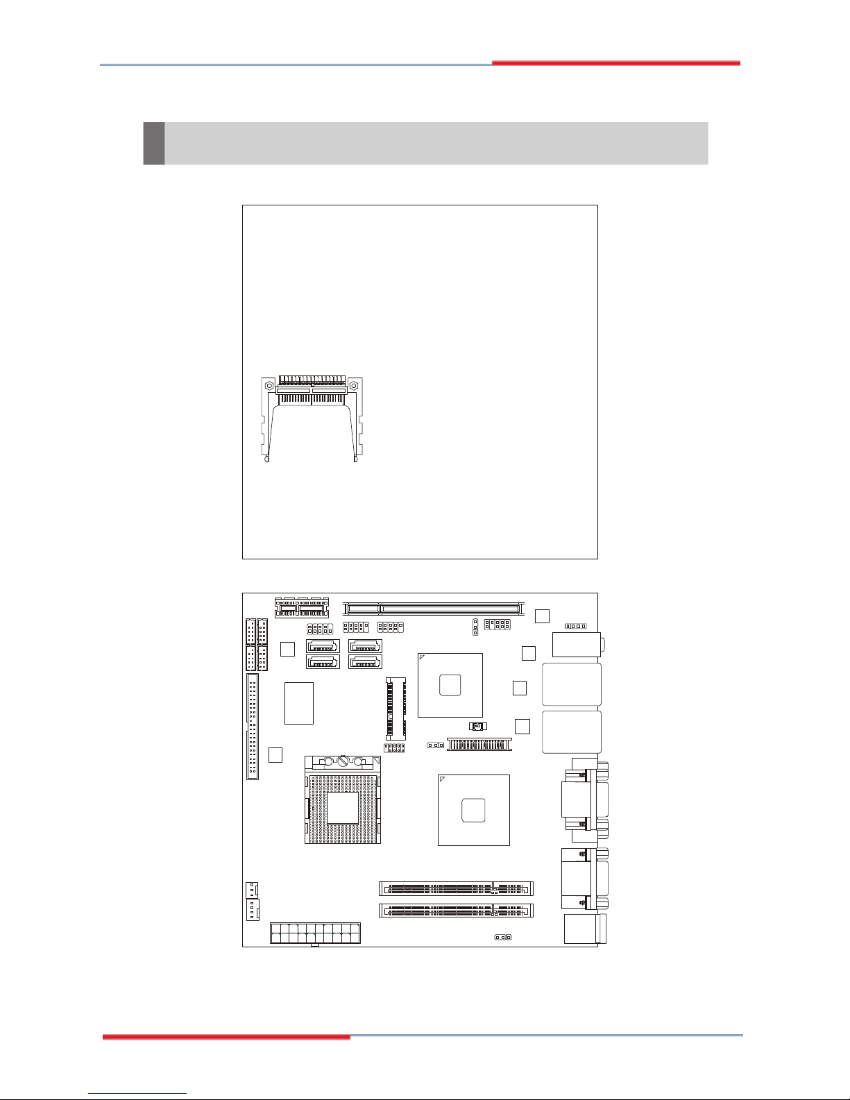
Mainboard Layout
CF1
Product Overview
JUSB2
CON 1
JSPI1
PCI1
JSPD1
Intel
ICH9M-E
J2
JLVDS1
Intel
GM45
PCI_E1
IDE 1
SYSFA N1
COM 2
COM3
COM 4
COM 5
JMB368
JFP1
JUSB1
SATA2 SATA4
SATA1
SATA3
DIMM1
CP UFAN1
ATX1
DIMM2
2808060 Mini ITX Mainboard
JAUD1
J1
Audio
Top: LAN1 Jack
LAN
Bottom: USB Ports
Top: LAN2 Jack
LAN
Bottom: USB Ports
JAMP1
T: Line-In
M: Line-Out
B: Mic-In
Top:
VGA Port
Bottom:
DVI Port
Top:
Serial Port
Bottom:
HDMI Port
Top: Mouse
Bottom:
Keyboard
1-5
2808060 Mainboard
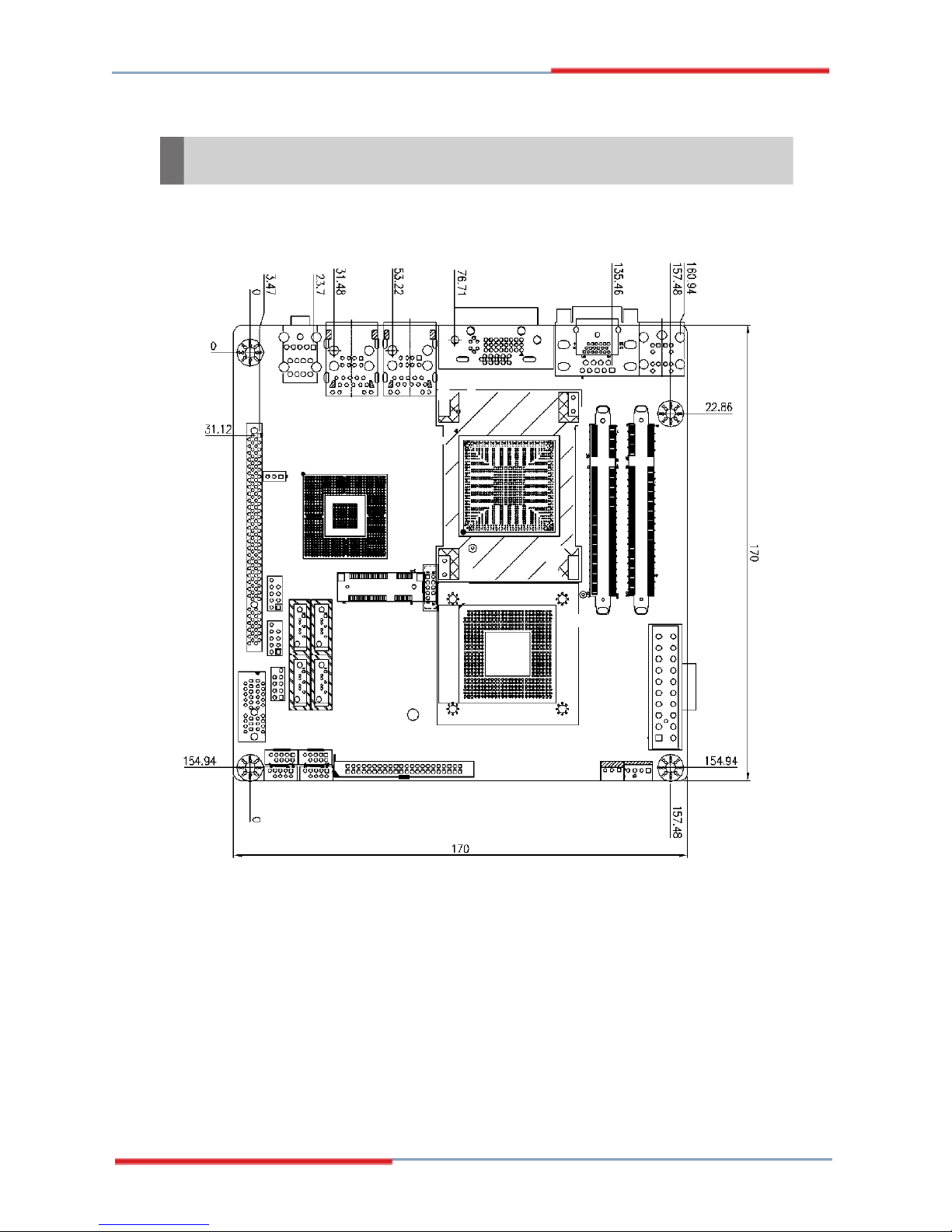
Board Dimension
1-6
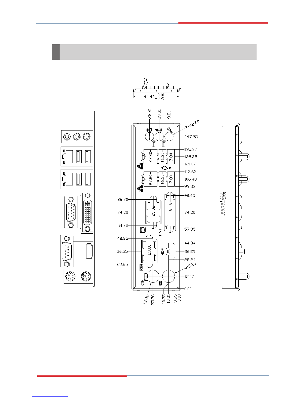
Back Panel & I/O Shield Drawing
Product Overview
1-7
2808060 Mainboard
Power Consumption
Component Description
CPU Intel Core 2 Duo 2.2G CPU
Memory Transcend 667MHz DDR2 1GB
Add-On VGA NA
Hard Disk Seagate Momentus 5400.3 160 GB SATA Hard Drive
Operating system Microsoft Windows XP Professional SP2
Current Current Current Current
+3.3V 0.700
+5V 1.540
+12V 0.390
+5VSB 56.00
-12V 42.00
Power line @115VoltsAC
TOTAL POWER 15.474
0.170
A
A
A
mA
mA
A
Watts
0.720
1.620
2.530
54.00
45.00
0.470
41.646
A
A
A
mA
mA
A
Watts
0.700
2.970
1.400
56.00
36.00
0.310
34.672
A
A
A
mA
mA
A
Watts
XcopyIdle Stress utility 3DMARK
0.69
2.62
0.56
57.000
44.00
0.40
22.910
A
A
A
mA
mA
A
Watts
1-8
Current
+3.3V 0.64
+5V 1.36
+12V 0.42
+5VSB 52.000
-12V 40.00
Power line @115VoltsAC
TOTAL POWER 14.692
0.20
S1 S3
Current
A A A
A A A
A A A
mA
mA mA mA
Watts
345.000
A
63.00
1.725
mA
mA
Watts
218.000
50.00
1.090
Soft Off
Current
mA
mA
Watts

Safety Compliance & MTBF
Limits for harmonic current
Limitation of voltage
voltage supply system
Product Overview
Certification Title of standard
Standard number
EN 55022:1998+A1:2000+A2:2003 Class BProduct family standard
CE
EN 6100-3-2:2000 Class D
RFI
EN 6100-3-3:1995+A1:2001
emission
fluctuation and flicker in low-
ImmunityEN 55024:1998+A1:2001+A2:2003 Product family standard
BSMI
C-Tick
FCC
VCCI
CNS 13438 乙類(1997年版)
AS/NZS CISPR 22:2004
FCC CFR Title 47 Part 15 Subpart B: 2005 Class B
CISPR 22: 2005
VCCI V-3:2004, Class B
VCCI V-4:2004, Class B
MTBF - Reliability Prediction
Calculation Model
Telcordia Issue 1 35
Operation
Temperature (°C)
Operating
Environment
GF, GU –Ground Fixed,
Uncontrolled
Duty Cycle MTBF(hr.)
13,575.994631 73,659
1-9

This page is intentionally left blank.
viii

Hardware Setup
Chapter 2
Hardware Setup
This chapter provides you with the information about
hardware setup procedures. While doing the installation,
be careful in holding the components and follow the
installation procedures. For some components, if you
install in the wrong orientation, the components will not
work properly.
Use a grounded wrist strap before handling computer
components. Static electricity may damage the
components.
2-1

2808060 Mainboard
Quick Components Guide
JFP1, p.2-12
JUSB1~2, p.2-14
PCI_E1, p.2-17
COM2~5, p.2-15
CON1, p.2-17
IDE1, p.2-9
PCI1, p.2-17
JSPD1, p.2-10
JAUD1, p.2-11
JAMP1, p.2-11
SATA1~4,
p.2-10
JSPI1, p.2-15
CPU, p.2-4
SYSFAN1, p.2-12
CPUFAN1, p.2-12
ATX1, p.2-6
DIMM Slots, p.2-3
J2, p.2-16
J1, p.2-16
JLVDS1,
p.2-13
Back Panel
I/O, p.2-7
2-2

Hardware Setup
Memory
The DIMM slots are intended for system memory modules.
DDR2 SO-DIMM Slot
200-pin, 1.8V
Installing Memory Modules
1. Locate the SO-DIMM slots on the mainboard.
2. Align the notch on the DIMM with the key on the slot. Insert the DIMM vertically into
the SO-DIMM slot. Then push it in until the golden finger on the DIMM is deeply
inserted in the SO-DIMM slot.
3. Manually check if the DIMM has been locked in place by the retaining clips at the
sides.
Important
1. Make sure that you install the memory modules first before installing
the CPU and cooler set.
2. Always insert the memory module into the DIMM1 first.
2-3

2808060 Mainboard
CPU (Central Processing Unit)
The mainboard supports Intel® Penryn/Core 2 Duo/Celeron M processors in
Socket P. When you are installing the CPU, make sure the CPU has a heat sink
and a cooling fan attached on the top to prevent overheating. If you do not
have the heat sink and cooling fan, contact your dealer to purchase and install them
before turning on the computer.
Important
1. Overheating will seriously damage the CPU and system. Always make
sure the cooling fan can work properly to protect the CPU from overheating.
2. Make sure that you apply an even layer of heat sink paste (or thermal tape)
between the CPU and the heatsink to enhance heat dissipation.
3. While replacing the CPU, always turn off the power supply or unplug the
power supply’s power cord from the grounded outlet first to ensure the
safety of CPU.
2-4
Hardware Setup
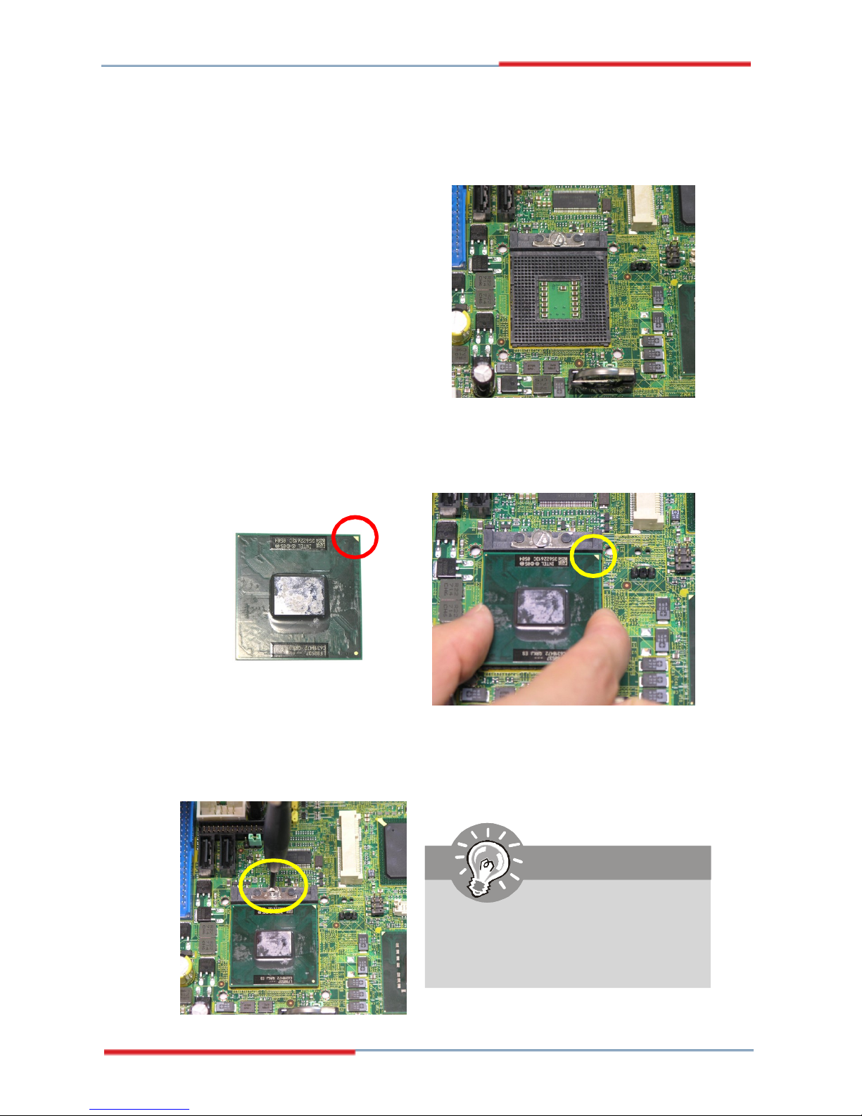
Socket P CPU Installation
1. Locate the CPU socket on the
mainboard.
2. Place the CPU on top of the socket. Make sure that you align the gold arrow on the
CPU with the arrow key on the socket.
3. Push the CPU down until its pins securely fit into the socket.
4. On the front end of the CPU socket is a locking mechanism designed into the form
of a screw head. Make sure that you actuate or deactuate this mechanism with
a screwdriver before and after installing the CPU.
Important
Mainboard photos shown in this
section are for demonstration only
and may differ from the actual look
of your mainboard.
2-5
2808060 Mainboard
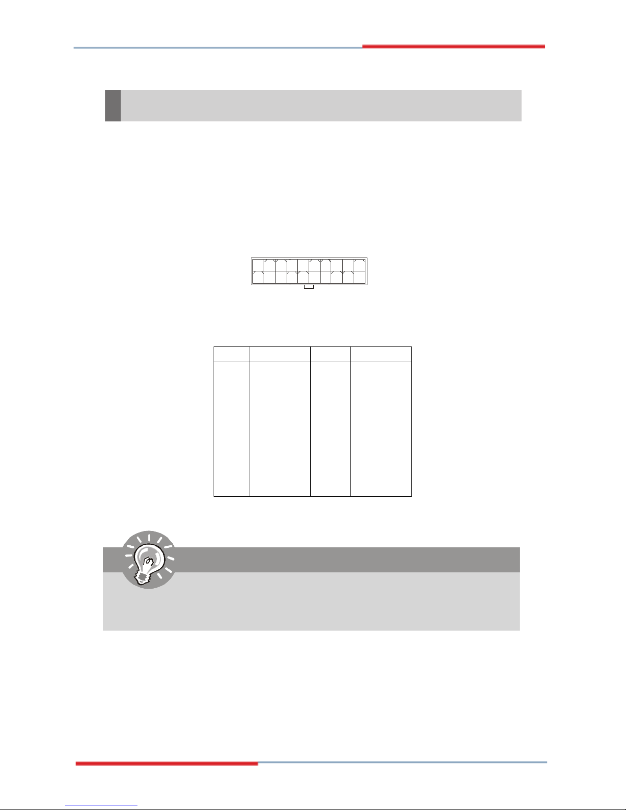
Power Supply
ATX 20-Pin System Power Connector: ATX1
This connector allows you to connect to an ATX power supply. To connect to the ATX
power supply, make sure the plug of the power supply is inserted in the proper
orientation and the pins are aligned. Then push down the power supply firmly into the
connector.
ATX1
1
11
Pin Definition
PIN SIGNAL
1 3.3V
2 3.3V
3 GND
4 5V
5 GND
6 5V
7 GND
8 PW_OK
9 5V_SB
10 12V
10
20
PIN SIGNAL
11 3.3V
12 -12V
13 GND
14 PS_ON
15 GND
16 GND
17 GND
18 -5V
19 5V
20 5V
Important
Power supply of 200watts (and above) is highly recommended for system
stability.
2-6
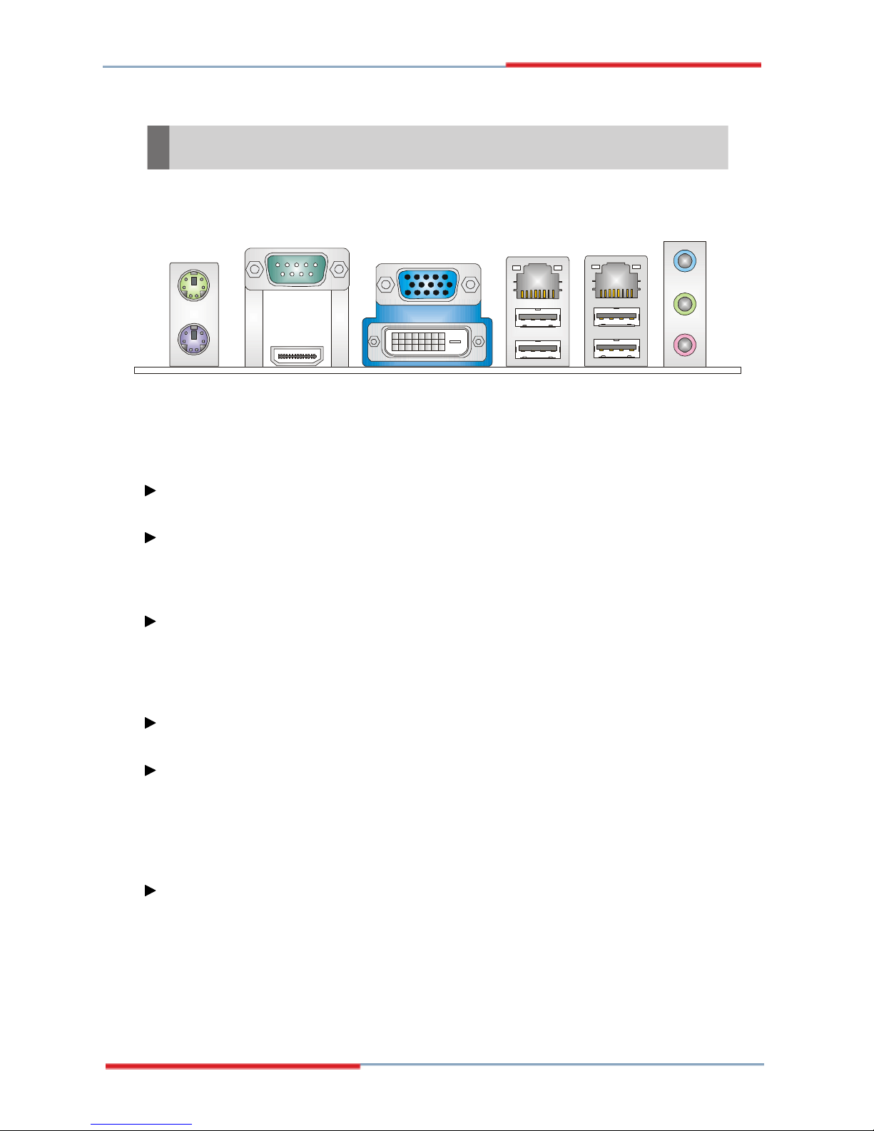
Back Panel
RS-232/422/485
Mouse
Serial Port
VGA Port
LAN
Hardware Setup
LAN
Line-In
Line-Out
Keyboard USB Ports
Mouse/Keyboard
The standard PS/2® mouse/keyboard DIN connector is for a PS/2® mouse/keyboard.
Serial Port
The serial port is a 16550A high speed communications port that sends/ receives 16
bytes FIFOs. You can attach a serial mouse or other serial devices directly to the
connector.
HDMI Port
The High-Definition Multimedia Interface (HDMI) is an all-digital audio/video interface
capable of transmitting uncompressed streams. HDMI supports all TV format, including standard, enhanced, or high-definition video, plus multi-channel digital audio on a
single cable.
VGA Port
The DB15-pin female connector is provided for monitor.
DVI-D Port
The DVI-D (Digital Visual Interface-Digital) connector allows you to connect an LCD
monitor. It provides a high-speed digital interconnection between the computer and
its display device. To connect an LCD monitor, simply plug your monitor cable into the
DVI connector, and make sure that the other end of the cable is properly connected
to your monitor (refer to your monitor manual for more information.)
USB Ports
MICHDMI Port DVI Port
USB Port
The USB (Universal Serial Bus) port is for attaching USB devices such as keyboard,
mouse, or other USB-compatible devices.
2-7
2808060 Mainboard
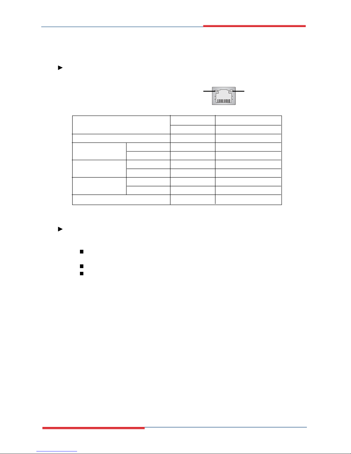
LAN
The standard RJ-45 LAN jack is for connection to the Local Area Network (LAN). You
can connect a network cable to it.
Speed IndicatorActivity Indicator
Left LED Right LED
Active LED 100M/1000M Speed LED
LED Color Yellow Green/Orange
10M Cable Plug-in No Transmission OFF OFF
Transition Yellow(Blinking) OFF
100M Cable Plug-in No Transmission OFF Green(Lighting)
Transition Yellow(Blinking) Green(Lighting)
1000M Cable Plug-in No Transmission OFF Orange(Lighting)
Transition Yellow(Blinking) Orange(Lighting)
In S3/S4/S5 Standby State Green (Lighting) OFF
Audio Ports
These audio connectors are used for audio devices. You can differentiate the color
of the audio jacks for different audio sound effects.
Line-In (Blue) - Line In, is used for external CD player, tapeplayer or other
audio devices.
Line-Out (Green) - Line Out, is a connector for speakers or headphones.
Mic (Pink) - Mic, is a connector for microphones.
2-8
 Loading...