

Global American 2808040 User Manual

2808040 User’s Manual
Version 1.0
Mini-ITX Motherboard with Socket LGA 775

Copyrights
This document is copyrighted and all rights are reserved. It does not allow any non
authorization in copied, photocopied, translated or reproduced to any electronic or
machine readable form in whole or in part without prior written consent from the
manufacturer.
In general, the manufacturer will not be liable for any direct, indirect, special, incidental
or consequential damages arising from the use of inability to use the product or
documentation, even if advised of the possibility of such damages. The manufacturer
keeps the rights in the subject to change the contents of this document without prior
notices in order to improve the function design, performance, quality and reliability. The
author assumes no responsibility for any errors or omissions, which may appear in this
document, nor does it make a commitment to update the information contained herein.
Trademarks
Intel is a registered trademark of Intel Corporation.
Award is a registered trademark of Award Software, Inc.
All other trademarks, products and or product's name mentioned herein are mentioned
for identification purposes only, and may be trademarks and/or registered trademarks of
their respective companies or owners.

iii
Table of Contents
Introduction ....................................................... 1
Checklist .............................................................................. 1
Product Description ............................................................. 2
Specifications ...................................................................... 3
Board Dimensions ............................................................... 4
Installations ....................................................... 5
Installing the CPU ............................................................... 6
ATX Power Installation ...................................................... 6
Installing the Memory ......................................................... 7
Setting the Jumpers ............................................................. 8
Connectors on 2808040...................................................... 11
Appendix ........................................................... 21
A. I/O Port Address Map ................................................... 21
B. Interrupt Request Lines (IRQ) ...................................... 22
C. Watchdog Timer Configuration .................................... 2
3

iv
This page is intentionally left blank.

1
Introduction
Checklist
Your
2808040 Core 2 Duo motherboard package should include the it em s
listed
below:
•
The 2808040 motherboard
• Th
is User’s manual
• 1 x I/O shield
• 1 x IDE cable
• 1 x SATA cable
• 1 CD containing the following:
• Chipset Drivers
• Flash Memory Utility

2
Product Description
The 2808040 Mini-ITX motherboard is designed for either the Intel®
Core™2 Duo or Core™2 Quad processors of up to 1333MHz FSB.
It is based on the Intel’s Q35 Express chipset and it comes with
two single-channel DDR2 memory slots and 4GB memory
capacity for faster system responsiveness and support of 64-bit
computing. The new GAI
motherboards are aimed for high
performance PCs in the digital, communications and industrial
sector.
On board is one PCI Express x16 slot that offers up to 3.5X the
bandwidth over traditional PCI architecture to support the latest
high-performance graphics cards. Dual independent display
comes to life with the onboard Intel® Q35 integrated graphics for
CRT and an optional SDVO card supporting either an LVDS or
DVI display interface. LAN functionality is supported with a 10/100
Ethernet controller or with two Gigabit Ethernet controllers.
2808040 is expandable, with the use of an adaptor card, 1008097, to
support 2 or 4 serial ports, or 10080
98 to support TPM 1.2 security
function. Other useful features on the board include two SATA II
ports, one eSATA port, eight USB 2.0 interface, watchdog timer,
digital I/O and two serial ports. Board dimensions are 170mm by
170mm. (Note: CPU power consumption – under 95watt
recommended.)
2808040 FEATURES
y Intel® Q35 Express Chipset
Based
y Support LGA775 Intel® Core™2 Duo/Quad CPU
y Support up to 1333MHz FSB
y Support up to 4GB DDRII 800/667 memory
y 1 x PCI Express (x16)
y Support one 10/100 or two Gigabit LAN on board
y 2x SATA II, 1x eSATA, 1x IDE, 8x USB 2.0,
2x COM, 7.1Ch.HD Audio
3
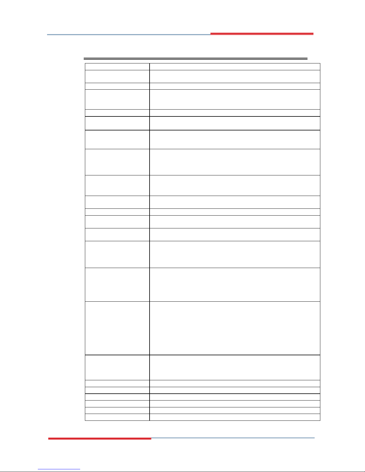
Specifications
Form Factor
Mini ITX (for performance desktop market)
Processor
Socket LGA775, Supports the Intel Core 2 Duo and Intel Core2 Quad
processors, and Intel Celeron 400 (Conroe-L) Sequence processor.
FSB
800/1066/1333 MHz
Chipset
Intel Q35 Chipset:
• Intel Q35 Graphic Memory Controller Hub (GMCH)
• Intel ICH9/ICH9R I/O Controller Hub
BIOS
• Award BIOS: footprint from SPI, supports ACPI, SMBIOS
Memory
• 2 x 240-pin DDRII 667/800 DIMM sockets, support one channels,
• Supports max. 4 GB system memory
Video
Intel Q35 integrated graphic subsystem (GMA3100), dual
independent display available through on-board VGA and PCI-e
x16 expansion adapter (DVI or LVDS) or VGA card
LAN
LAN1: dual Footprint support option:
•Intel 82566DM Nineveh 10/100/1000 LAN
•Intel 82562V Ekron-N 10/100
LAN2: Marvell 88E8053 PCI-express Gigabit LAN controller x1
USB
Intel ICH9/ICH9R built-in USB 2.0 host controller, supports 8 ports:
•4 ports in the rear I/O region
•4 ports with on-board headers
SATA II
Intel ICH9 built-in SATA II controller (3.0Gb/sec) w/ 2 ports. ICh9R
Built-in raid 0,1 or AHCI (for eSATA)
IDE
Jmicron JM368 (PCI-e to PATA) x1 for 1 PATA channel
Audio
Intel ICH9/ICH9R built-in high definition audio w/ Realtek ALC888
Codec
LPC I/O
Winbond W83627EHG: COM1 (RS232), COM2 (RS232/422/485) &
Hardware monitor
Hardware Monitor
• Two fan connectors with tachometer support
• CPU fan connector supports 4-wire fan with PWM control
• Supports three thermal diodes (CPU die + 2 on-board)
• Voltage monitoring for VCC (processor), 3.3V, 5V, and 12V
Edge Connectors
• Mini-DIN x 1 for PS/2 KB & MS
• Esata connectorx1(for ICH9R)
• DB9 + DB15 stack connector x 1 for COM1 & VGA
• RJ45 + dual USB stack connector x2 for LAN1~2 and USB1~4
• Triple (3x1) phone jack connector x1 for High-Definition Audio
On Board Headers /
Connectors
• Standard SATA (7-pin shrouded vertical) connector x2
• 4x2 pins pin-header x2 for USB 5-6,7-8.
• 5x2 pins x1 for COM2 (RS232/422/485)
• 5x2 pins pin-header x1 for Digital I/O
• 5X2 pins pin-headerx1 for audio front.
• 40 pins box-header x1 for IDE
• 4 pins pin--header x1 for CPU fan & system fan
• 3 pins pin--header x2 for system fan
Expansion
PCI-express (x16) slot x1
8x2 pins pin header x1 for adaptor card:
- 1008097 (2 or 4 serial ports)
-
1008098 (TPM function)
Watchdog Timer
Yes (256 segments, 0, 1, 2…255 sec/min)
Digital IO
4 in and 4 Out
Other
LAN Wakeup
Power Connector
24 pins ATX main power + 4 pins 12V
System Voltage
+5V, +3.3V, +12V, -12V & 5VSB
Board Size
170 x 170mm
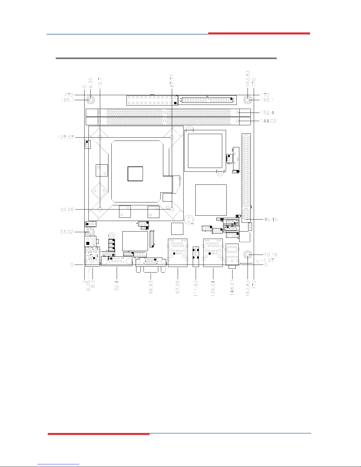
Board Dimensions
4

5
Installations
This section provides information on how to use the jumpers and
connectors on the
2808040 in order to set up a workable system. The
t
opics covered are:
Installing the CPU ........................................................................ 6
ATX Power Installation ............................................................... 6
Installing the Memory .................................................................. 7
Setting the Jumpers ...................................................................... 8
Connectors on 2808040............................................................... 11
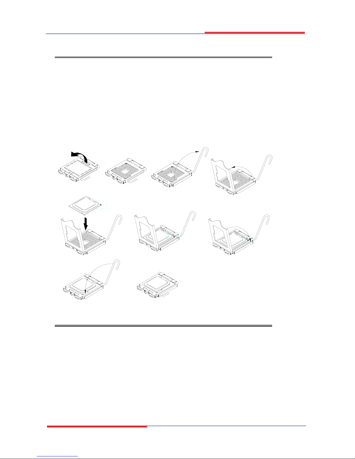
Installing the CPU
The
2808040 motherboard supports an LGA 775 processor socket for
Int
el® Core 2 Duo processors.
The LGA 775 processor socket comes with a lever to secure the
processor. Refer to the pictures below, from left to right, on how to place
the processor into the CPU socket. Please note that the cover of the
LGA775 socket must always be installed during transport to avoid
damage to the socket.
ATX Power Installation
The system power is provided to the motherboard with the ATX2 and
ATX1 power connectors. ATX2 is a 24-pin power connector and ATX1
is a 4-pin 12V power connector.
The 24-pin power connector can to be connected to a standard 20-pin
ATX power connector in a standard ATX power supply (Min. 400watt).
Note: The power supply 5VSB voltage must be at least 2A.
6
 Loading...