

Global American 2807930 User Manual

2807930 User’s Manual
Version 1.0
ATX Industrial Motherboard

Copyrights
This document is copyrighted and all rights are reserved. It does not allow any non
authorization in copied, photocopied, translated or reproduced to any electronic or
machine readable form in whole or in part without prior written consent from the
manufacturer.
In general, the manufacturer will not be liable for any direct, indirect, special, incidental
or consequential damages arising from the use of inability to use the product or
documentation, even if advised of the possibility of such damages. The manufacturer
keeps the rights in the subject to change the contents of this document without prior
notices in order to improve the function design, performance, quality and reliability. The
author assumes no responsibility for any errors or omissions, which may appear in this
document, nor does it make a commitment to update the information contained herein.
Trademarks
Intel is a registered trademark of Intel Corporation.
Award is a registered trademark of Award Software, Inc.
All other trademarks, products and or product's name mentioned herein are mentioned
for identification purposes only, and may be trademarks and/or registered trademarks of
their respective companies or owners.

- i -
Table of Contents
Chapter 1 - Introduction ............................................ 1
1.1 Copyright Notice ...................................................2
1.2 About this User’s Manual .....................................2
1.3 Warning..................................................................2
1.4 Replacing the lithium battery
..............................3
1.5 Technical Support .................................................3
1.6 Warranty
................................................................4
1.7 Packing List ...........................................................5
1.8 Ordering Information ............................................5
1.9 Specication
.........................................................6
1.10 Board Dimensions ..............................................7
1.11 Installing the CPU
...............................................8
1.12 Installing the Memory .........................................9
Chapter 2 - Installation ............................................ 11
2.1 Block Diagram .....................................................12
2.2 Jumpers and Connectors
..................................13
Jumpers ......................................................................14
JP3: PATA IDE Select ............................................14
JBAT1: CMOS Setup
.............................................14
JRS1: COM2 RS-232/422/485 Mode Select ..........15
JP2: AT/ATX Power Mode Select
..........................16
JP1: BIOS Write Protect ........................................16
Connectors .................................................................17
SATA1 ~4: Serial ATA Connectors
........................17
IDE1: Primary IDE Connector ...............................18
TPM1: Trusted Platform Module Connector
........19
USB1 ~3: USB Connectors ...................................19
JFRT1: Switches and Indicators ..........................20
COM2: RS-232/422/485 Connector
.......................21
FDD1: FDD Connector ...........................................21
DIO1: Digital I/O Connector
..................................22
CDIN1: Audio CD IN Connector ............................22

- ii -
LOUT1: Audio Line Out Connector ......................22
ATX1: ATX Power Supply Connector
...................23
ATX12V1: ATX +12V Connector ............................23
EKB1: External Keyboard/ Mouse Connector.....24
SYSF1/SYSF2: System Fan Power Connectors..24
CPUF1: CPU Fan Power Connector
.....................24
Audio1/ Audio2: HD Audio Phone Jacks
.............25
LAN1/LAN2: RJ-45 & double stack USB
Connectors.......................................25
VGA1: CRT Connector
..........................................26
COM1: RS-232 Connector .....................................26
LPT1: Parallel Port Connector..............................27
KBM1: PS/2 Keyboard & Mouse Connectors
......27
2.3 The Installation Paths of CD Driver
...................28

- 1 -
1Chapter 1
Introduction
Chapter 1 - Introduction

- 2 -
1.2 About this User’s Manual
This User’s Manual is intended for experienced users and integrators with
hardware knowledge of personal computers. If you are not sure about any
description in this User’s Manual, please consult your vendor before further
handling.
1.3 Warning
Single Board Computers and their components contain very delicate
Integrated Circuits (IC). To protect the Single Board Computer and its
components against damage from static electricity, you should always follow
the following precautions when handling it :
1. Disconnect your Single Board Computer from the power source when you
want to work on the inside.
2. Hold the board by the edges and try not to touch the IC chips, leads or
circuitry.
3. Use a grounded wrist strap when handling computer components.
4. Place components on a grounded antistatic pad or on the bag that came
with the Single Board Computer, whenever components are separated
from the system.

- 3 -
1.4 Replacing the lithium battery
Incorrect replacement of the lithium battery may lead to a risk of explosion.
The lithium battery must be replaced with an identical battery or a battery
type recommended by the manufacturer.
Do not throw lithium batteries into the trashcan. It must be disposed of in
accordance with local regulations concerning special waste.

- 4 -
1.6 Warranty
This product is warranted to be in good working order for a period of two
years from the date of purchase. Should this product fail to be in good
working order at any time during this period, we will, at our option, replace
or repair it at no additional charge except as set forth in the following terms.
This warranty does not apply to products damaged by misuse, modications,
accident or disaster.
Vendor assumes no liability for any damages, lost prots, lost savings or any
other incidental or consequential damage resulting from the use, misuse of,
or inability to use this product. Vendor will not be liable for any claim made
by any other related party.
Vendors disclaim all other warranties, either expressed or implied, including
but not limited to implied warranties of merchantibility and tness for
a particular purpose, with respect to the hardware, the accompanying
product’s manual(s) and written materials, and any accompanying
hardware. This limited warranty gives you specic legal rights.
Return authorization must be obtained from the vendor before returned
merchandise will be accepted. Authorization can be obtained by calling or
faxing the vendor and requesting a Return Merchandise Authorization (RMA)
number. Returned goods should always be accompanied by a clear problem
description.

- 5 -
1.7 Packing List
If any of the above items is damaged or missing, contact your vendor
immediately.
1 x 2807930 ATX Industrial Motherboard
1 x Driver CD
1 x Quick Installation Guide
COM Port Cable x 1
IDE Cable x 1
USB Cable x 1
SATA Cable x 2
- 6 -
1.9 Specications
Form Factor ATX Industrial Motherboard
Processor
Socket for Intel® Core™ 2 Duo/ Pentium®
D/ Celeron® D/ Pentium® 4 processor, with
1066/800/533MHz FSB, w/ HT
Chipset Intel® Q965 + Intel® ICH8R
System Memory 2 x 240-pin DIMM socket up to 4GB
VGA Controller
Intel® Graphics Media Accelerator (GMA) 3000
graphics core w/ CRT (Dual independent display)
Ethernet
2 x Realtek 8111B 10/100/1000 base-T Ethernet
I/O Chips ITE-8718
BIOS AMI PnP Flash BIOS
Audio
ALC888 HD Codec
7.1 channel/MIC-in/Line-in/Line-out
Serial ATA 4 x Serial ATA with 300MB/s HDD transfer rate
IDE Interface
1 x ATA 66/100, support 1 IDE device
Serial Port
2 x COM port
(COM1: RS-232, COM2: RS-232/422/485)
Parallel Port 1 x SPP/EPP/ECP mode
FDD 1 x Slim type Floppy connector
KBMS PS/2 Keyboard and Mouse
External KBMS
1 x 6-pin wafer connector
Universal Serial Bus 10 x USB 2.0 (6 ports by pin header)
Digital I/O Onboard 8-bit Digital I/O Interface
Expansion Interface
1 x PCIe*16 slot, 5 x PCI slot, 1 x ISA slot
Hardware Monitor Chip
♦ CPU/System temperature and over heat Alarm
♦ 12V/5V/3.3V/Vcore/Vbat/5Vsb/3.3Vsb Voltage
♦ CPU/System Fan speed
♦ CPU over heat Protection
RTC Real Time Clock
Power Input Connector
24-pin ATX power connector & +12V 4-pin ATX
Power Connector
Operating Temp.
0ºC ~ 60ºC (-32ºF ~ 140ºF)
Watchdog Timer 255-level Reset
Dimension (L x W) 305 x 220mm (12” x 8.6”)
- 7 -
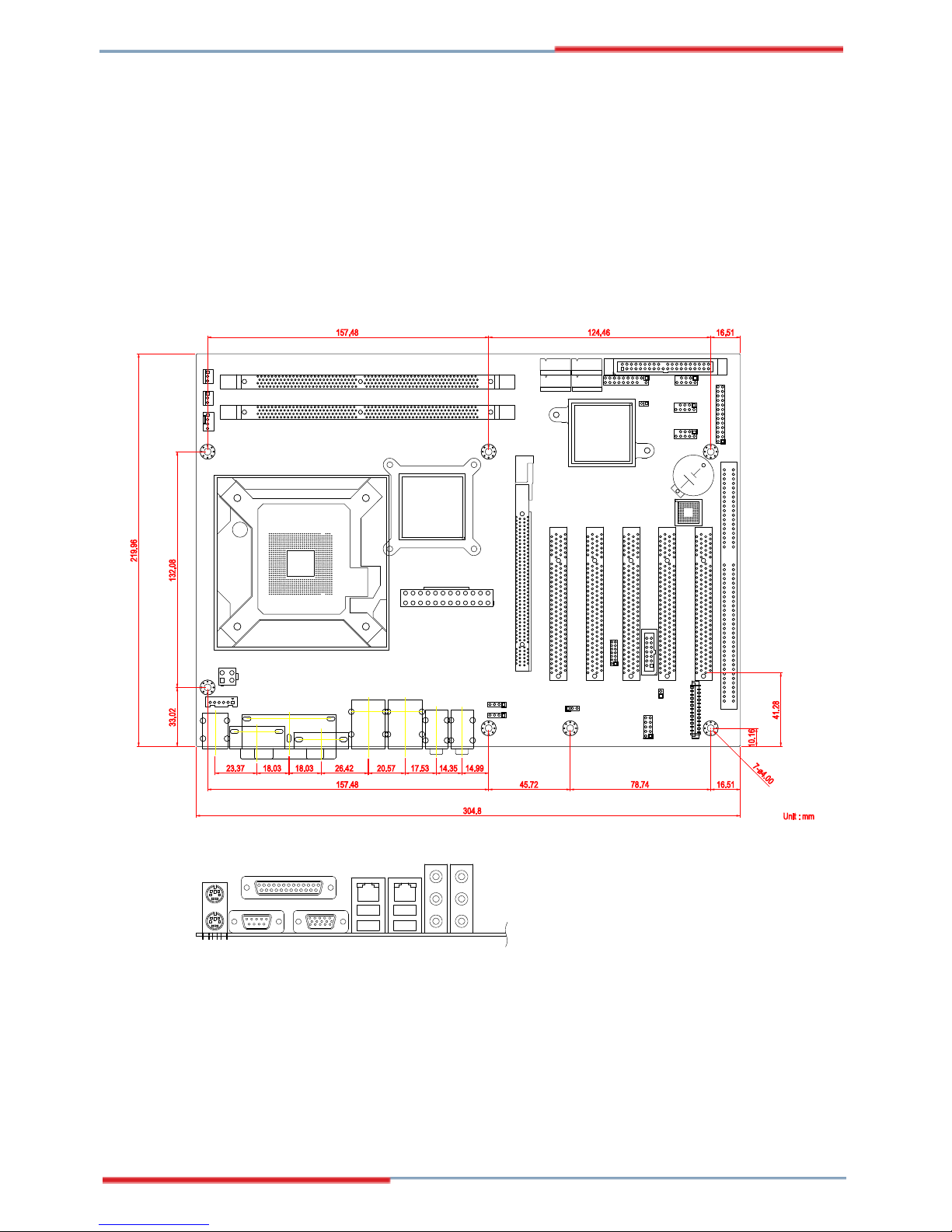
1.10 Board Dimensions
Unit : mm
78.74
45.72
16.51
304.8
157.48
14.9914.3517.5320.5726.4218.0318.0323.37
41.28
33.02 132.08
16.51124.46157.48
10.16
219.96
7-ø4.00
Mouse
Keyboard
USB1
USB2
USB3
USB4
Parallel Port
COM1 Port
VGA
 Loading...