

Global American 2807770 User Manual

ATX
Version 1.0,
User’s Manual
xMotherboardx
October 2007
2807770

Copyrights
This manual is copyrighted and all rights are reserved. It does not allow any non authorization in
copied, photocopied, translated or reproduced to any electronic or machine readable form in
whole or in part without prior written consent from the manufacturer.
In general, the manufacturer will not be liable for any direct, indirect, special, incidental or
consequential damages arising from the use of inability to use the product or documentation, even
if advised of the possibility of such damages. The manufacturer keeps the rights in the subject to
change the contents of this manual without prior notices in order to improve the function design,
performance, quality and reliability. The author assumes no responsibility for any errors or
omissions, which may appear in this manual, nor does it make a commitment to update the
information contained herein.
Trademarks
Intel is a registered trademark of Intel Corporation.
Award is a registered trademark of Award Software, Inc.
All other trademarks, products and or product's name mentioned herein are mentioned for
identification purposes only, and may be trademarks and/or registered trademarks of their
respective companies or owners.
2807770 User’s Manual
-2-
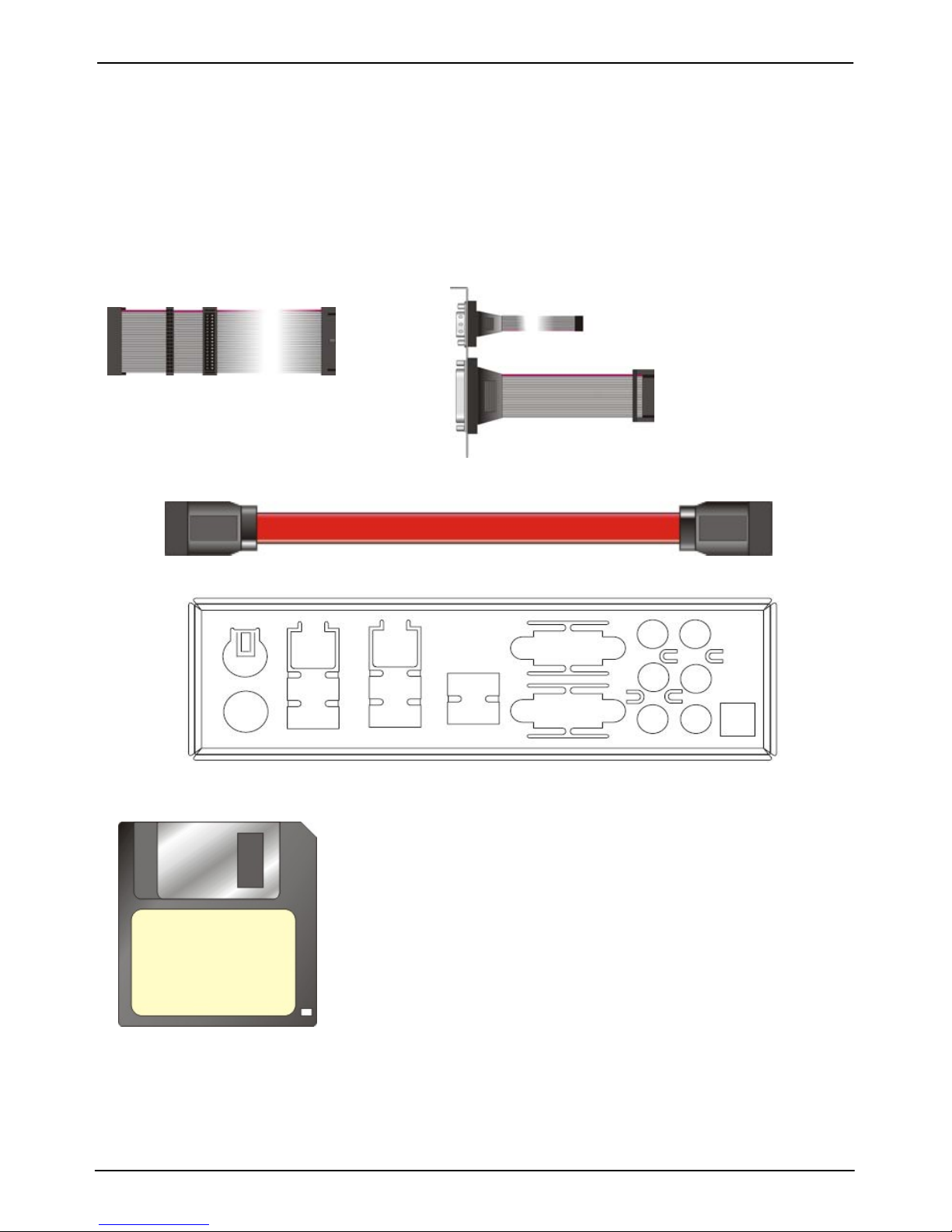
Packing List
Please check package component before you use our products.
Hardware:
2807770 Full size ATX motherboard x 1
Cable Kit:
Other Accessories:
Divers CD (including User’s Manual) x 1
Floppy flat cable x 1
DB25 & DB9 cable x 1
Serial ATA ribbon cable x 2
I/O Shield x 1
RAID driver Disk for Windows 2000,
Windows XP and Windows Server 2003

2807770 User’s Manual
-3-
Index
Chapter1 <Introduction>
.....................................................................6
1.1 <Product Overview>.................................................................................6
1.2 <Product Specification>...........................................................................7
1.3 <Component Placement> ........................................................................9
1.4 <Block Diagram>....................................................................................10
1.5 <Mechanical Drawing >.......................................................................... 11
Chapter 2 <Hardware Setup>.........................................................12
2.1 <Connector Location>............................................................................12
2.2 <Jumper Location> ................................................................................13
2.3 <Connector Reference>.........................................................................14
2.3.1 <Internal Connectors> ..............................................................14
2.3.2 <External Connectors> .............................................................14
2.4 <CPU and Memory Setup>....................................................................15
2.4.1 <CPU installation>...................................................................15
2.4.2 <Memory installation>..............................................................16
2.5 <CMOS Setup>......................................................................................17
2.6 <Serial ATA installation>.........................................................................18
2.7 <Floppy Installation>..............................................................................19
2.8 <LAN installation>..................................................................................20
2.9 <Audio Installation>................................................................................21
2.10 <Display Installation>...........................................................................23
2.11 <USB Installation>................................................................................24
2.12 <Power and Fan Installation> ..............................................................26
2.13 <GPIO & SMBUS interface>................................................................28
2.14 <Serial Port> ........................................................................................29
2.15 <Switch & Indicator>............................................................................31
2.16 <Expansion Interface>.........................................................................32

2807770 User’s Manual
-4-
Chapter 3 <System Configuration>...........................................34
3.1 <SATA configuration>.............................................................................34
3.2 <SATA RAID Configuration> ..................................................................35
3.3 <Audio Configuration> ...........................................................................39
3.4 <Video Memory Setup> .........................................................................40
Appendix A <I/O Port Pin Assignment>.................................44
A.1 <Floppy Port> ........................................................................................44
A.2 <Serial Port>..........................................................................................45
A.3 <VGA Port>............................................................................................45
A.4 <LAN Port>............................................................................................46
A.5 <SMBus>...............................................................................................46
A.6 <Parallel Port>.......................................................................................47
A.7 <IrDA Port>............................................................................................47
Appedix B <System Resources>................................................48
Appendix C <Programming GPIO’s>........................................53
Appendix D <What Dog timer Setting >..................................54
Contact Information..............................................................................55

2807770 User’s Manual
-5-
(This page is left for blank)

2807770 User’s Manual
-6-
Chapter1 <Introduction>
1.1 <Product Overview>
2807770 is the motherboard with last Intel desktop technology with industri al motherboard
form factor. Based on Intel® Q965 and ICH8DO, the board integrates a new Core 2 Quad
processor 775-pin socket, DDR2 memory slot, Intel® Graphic Media Accelerator 3000
technology, PCI express interface and Serial ATA II with RAID function for a powerful
desktop system.
Intel® LGA775 processor
The Intel® Core 2 Quad processor now comes with a new form factor with 775-pin PLGA
package, for 533/800/1066MHz front-side-bus, 4MB L2 cache, and for 65nm manufacturing
technology, the PLGA processor without pin header on solder side can make user i nstalling
the processor on the socket easier.
Intel® Q965 and ICH8DO chipset
The Intel Q965 integrates DDR2 533/667/800MHz for memory, and Graphic Media
Accelerator (GMA) 3000 technology for new graphic eng ine. It can provide up t o 256MB of
frame buffer when you install over 512MB of system memory. The ICH8D O integrates with
up to 10 USB2.0 interfaces (6 ports for 2807770) I/O panel, and serial ATA II interface with
RAID function.
Dual Intel 82573L Gigabit LAN
Dual Gigabit LAN with Intel 82573L, 2807770 comes with a powerful network function for the
system that requires large transfer data of NAS system or Server platform.
PCI-Express interface
2807770 integrates one x16 and x4 PCI-Express interface, it can provide up to 8GB/s of
bandwidth, which AGP 8x can only provide up to 2GB/s.
Multimedia interfaces
2807770also integrates 7.1 chan nel HD audio, Mini-PCI, PCI and ISA interface, for these
flexible function, system integrator can built more powerful systems for many applications.

2807770 User’s Manual
-7-
1.2 <Product Specification>
General Specification
Form Factor Full size ATX motherboard
CPU Intel® Core 2 Quad/Core 2 Duo/Pentium 4/Pentium D/
Celeron D series processor with LGA775 socket
Package type: PLGA 775
Front side bus: 533/800/1066MT/s (133/200/266/QuadMHz x 4)
Intel® Hyper-Threading Technology and Dual/Quad core
supported, EM64T supported
Memory 4 x 240-pin DDR2 533/667/800MHz SDRAM up to 8GB
Unbufferred, none-ECC memory supported only
Chipset Intel® Q965 (Northbridge) and ICH8DO (Southbridge)
BIOS Phoenix-Award v6.00PG 8Mb SPI flash BIOS
Green Function Power saving mode includes doze, standby and suspend modes.
ACPI version 1.0 and APM version 1.2 compliant
Watchdog Timer System reset programmable watchdog timer with 1 ~ 255
sec./min. of timeout value
Real Time Clock Intel® ICH8DO built-in RTC with lithium battery
Serial ATAII Intel® ICH8DO integrates 6 Serial ATA II interface
RAID 0, 1,5,10 Intel Matrix Storage Technology supported
Multi-I/O Port
Chipset Intel® 82801HDO(ICH8DO) with Winbond® W83627DHG and
Fintek F81216D controller
Serial Port Five RS-232 and one RS232/422/485 serial ports
USB Port Ten Hi-Speed USB 2.0 ports with 480Mbps of transfer rate
Parallel Port One internal bi-direction parallel port with SPP/ECP/EPP mode
Floppy Port One internal Floppy port
IrDA Port One IrDA compliant Infrared interface supports SIR
K/B & Mouse External PS/2 keyboard and mouse port on rear I/O
GPIO One 12-pin Digital I/O connector with 8-bit programmable I/O
interface
Smart Fan One CPU fan connector for fan speed controllable
VGA Display Interface
Chipset Intel® Q965 GMA3000 (Graphic Memory Controller Hub)
Frame Buffer Up to 256MB shared with system memory
Connector External DB15 female connector on rear I/O

2807770 User’s Manual
-8-
Ethernet Interface
Controller Two Intel 82573L Gigabit Ethernet controller
Type Triple speed 10/100/1000Base-T
Auto-switching Fast Ethernet
Full duplex, IEEE802.3U compliant
Connector Two External RJ45 connectors with LED on rear I/O
Audio Interface
Chipset Intel integrated with Realtek ALC888 HD Audio
Intel High Definition Audio compliance
Interface 7.1 channels sound output
Connector External Audio phone jack for Line-out, Line-in, MIC-in, Surround,
Center and Backsurround
Onboard front audio connector with pin header
Onboard CD-IN and external optical S/PDIF connector
Expansive Interface
PCI-Express One x16 PCI-Express slot (compatible with x1 slot)
One x4 PCI-Express slot (compatible with x 1 slot)
Up to 8GB/s of transfer bandwidth
Power supply: +3.3V, +12V
PCI Four-PCI slot (32-bit, 33MHz)
Power supply: +3.3V, +5V, +12V, -12V
Mini PCI One Mini-PCI socket TYPE III A (32-bit, 33MHz)
Power supply: +3.3V, +5V, 3VSB
ISA Two ISA slots (without DMA supported)
Power and Environment
Power Requirement Standard 24-pin ATX power supply (20-pin is compatible)
Standard 8-pin 12v power Input connector (4-pin is compatible)
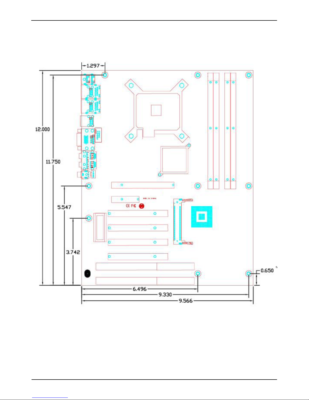
Dimension 307mm x 244mm (L x W)
Temperature Operating within 0 ~ 60oC (32 ~ 140oF)
Storage within -20 ~ 85
o
C (-4 ~ 185oF)
Ordering Code
2807770 Support Intel Core 2 Quad LGA775 with DDRII, Onboard VGA, Dual
Intel Gigabit LAN 10 x USB2.0, Realtek ALC888 HD Audio, 6 x
COM Ports, GPIO, SAT
A and ISA slot
For further product information please visit the website at http://www.globalamericaninc.com
2807770 User’s Manual
-9-
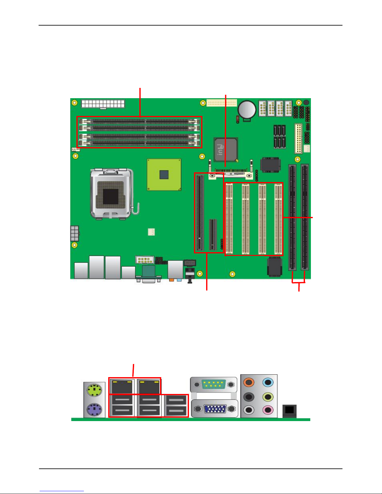
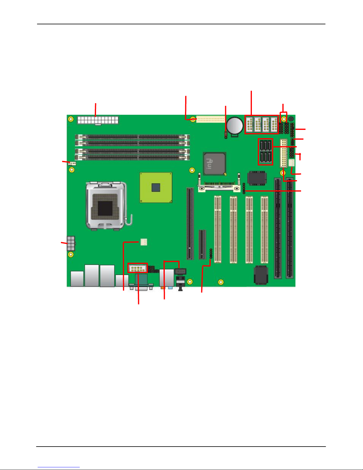
1.3 <Component Placement>
ISA
Mini PCI
PCI
PCI-Express
DIMM
Audio
VG
A
PS2
USB
SPDIF
LAN
Serial port
2807770 User’s Manual
-10-
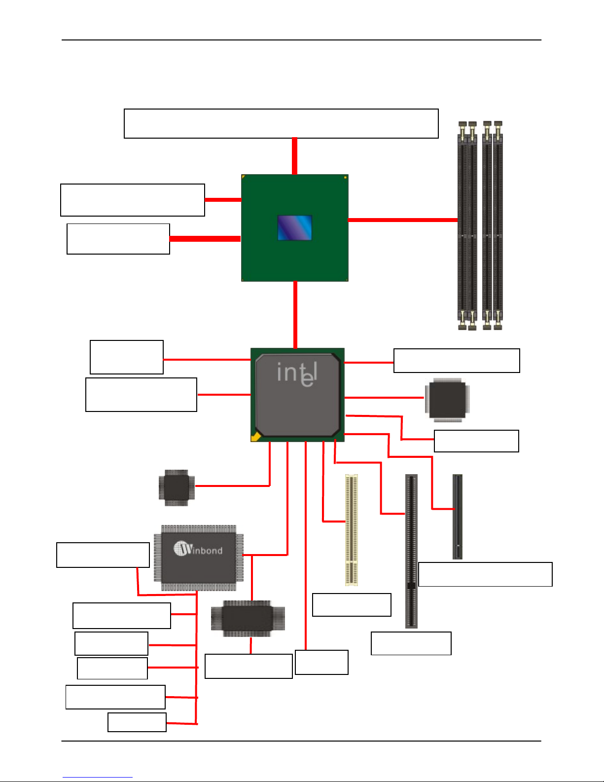
1.4 <Block Diagram>
Intel Core 2 Quad / Duo with 775 pin PLGA processor
6.4GB/s
Intel GMA3000 Graphics
PCI-Express x16
8GB/s
Intel Q965
4 x 240-pin DDR2
533/667/800MHz
up to 8GB
2GB/s DMI
6 x Serial ATA II ports
300MB/s
2 x Intel
82573L
4 x PCI bus
2 x Serial port
8-bit GPIO
10 x USB2.0 ports
HD Audio ALC888
SMBus 2.0
ICH8DO
2 x ISA bus
x4 & x16 PCI-Express
W83627DHG
1 x IrDA
BIOS
SPI
Mini-PCI slot
1 x Floppy port
1 x Parallel Port
KB/MS
F81216D
4 x serial port
2807770 User’s Manual
-11-
1.5 <Mechanical Drawing >
“
“
“
“
“
“
“
“
2807770 User’s Manual
-12-
Chapter 2 <Hardware Setup>
2.1 <Connector Location>
JFRNT
CN_DIO
SYSFAN
ATX
CN_USB1/2
FDD
JRTC
CN_12V
SATA II
CPUFAN
NBFAN
CN_A
UDIO
CN_SMBUS
COM Port 3~6
CN_LPT
IrDA
CDIN
COM2
2807770 User’s Manual
-13-
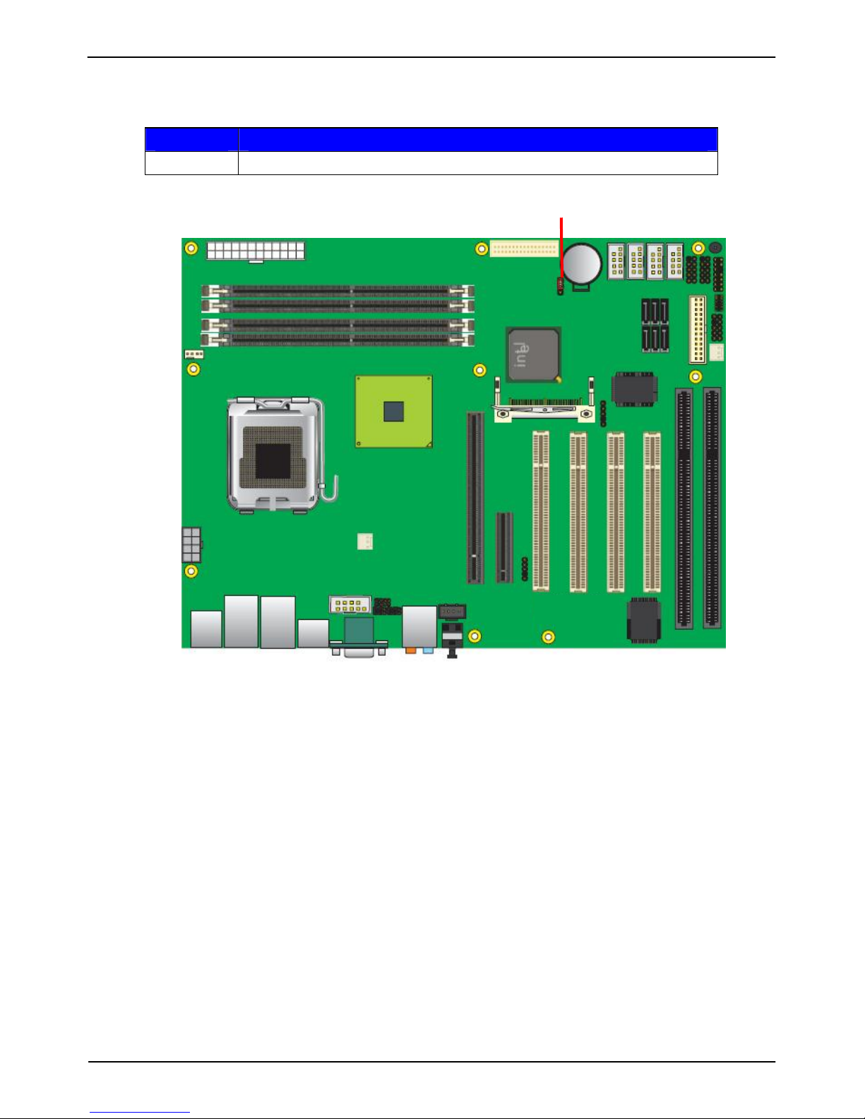
2.2 <Jumper Location>
Jumper Function
JRTC CMOS Operating/Clear Setting
JRTC

2807770 User’s Manual
-14-
2.3 <Connector Reference>
2.3.1 <Internal Connectors>
Connector Function
CPU PLGA775 CPU socket
DDRII1/2/3/4 240 -pin DDR2 SDRAM DIMM socket
S_ATAII1/2/3/4/5/6 7-pin Serial ATA II connector
ATX 24-pin power supply connector
CN_12V 8-pin +12V additional power supply connector
CN_AUDIO 5 x 2-pin audio connector
CDIN 4-pin CD-ROM audio input connector
CN_DIO 6 x 2-pin digital I/O connector
CN_USB1/2 10-pin USB connector
CPUFAN 4-pin CPU cooler fan connector
SYSFAN 3-pin system cooler fan connector
NBFAN 3-pin Northbridge cooler fan connector
CN_IR 5-pin IrDA connector
CN_SMBUS 5-pin I2C connector
JFRNT 14-pin front panel switch/indicator connector
FDD 26-pin slim type floppy connector
CN_COM2~6 5 x 2-pin com connector
2.3.2 <External Connectors>
Connector Function
VGA DB15 VGA connector
USB Dual USB Ports
COM DB9 Serial port connector
PS2 PS/2 Keyboard/Mouse connector
AUDIO Audio connector
USB_RJ45_A/B Quad USB and Dual RJ45 LAN connectors
SPDIF Optical SPDIF digital audio output connector
2807770 User’s Manual
-15-
2.4 <CPU and Memory Setup>
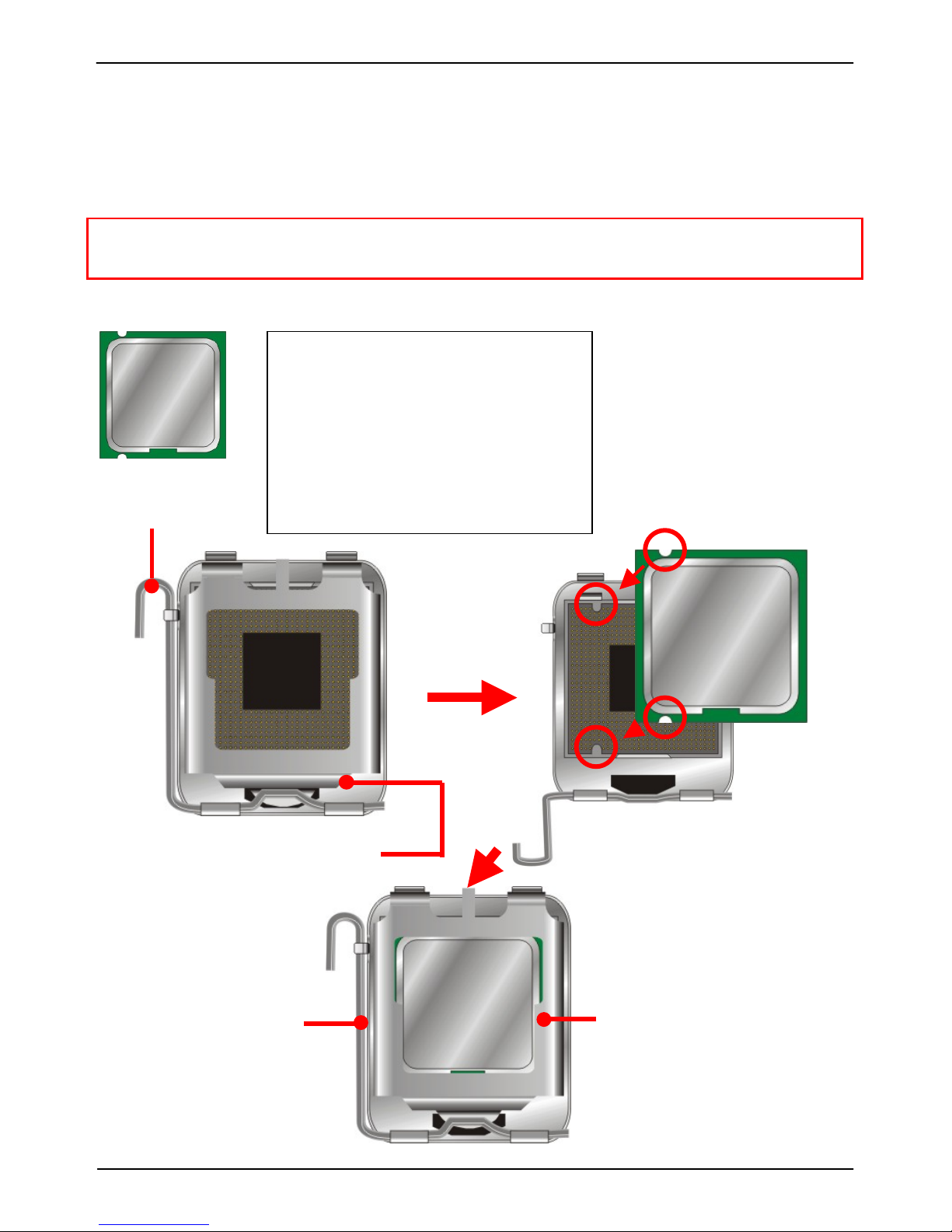
2.4.1 <CPU installation>
2807770 has a PLGA775 CPU socket onboard; please check follo wing steps to install the
processor properly.
Attention If 2807770 need RMA, please Keep CPU socket cover on the CPU Socket.
Warring If CPU Socket internal Pin damag e, we could not provide warran ty.
Intel® Core 2 Quad/Duo processor
Package type: 775 pin PLGA
L2 Cache: 4MB
FSB: 533/800/1066MT/S (266MHz x 4)
Manufacturing: 65nm, 90nm
Intel Hyper Threading Technology
And Core 2 Quad/Core 2 Duo support
1. Lift this bar
2. Uncover this plate
Check point
3. Place the CPU on the top of
the pins
3. Cover this plate
4. Lock this bar
Notice: Please place the CPU on the pins tenderly to avoid bending the pins
2807770 User’s Manual
-16-
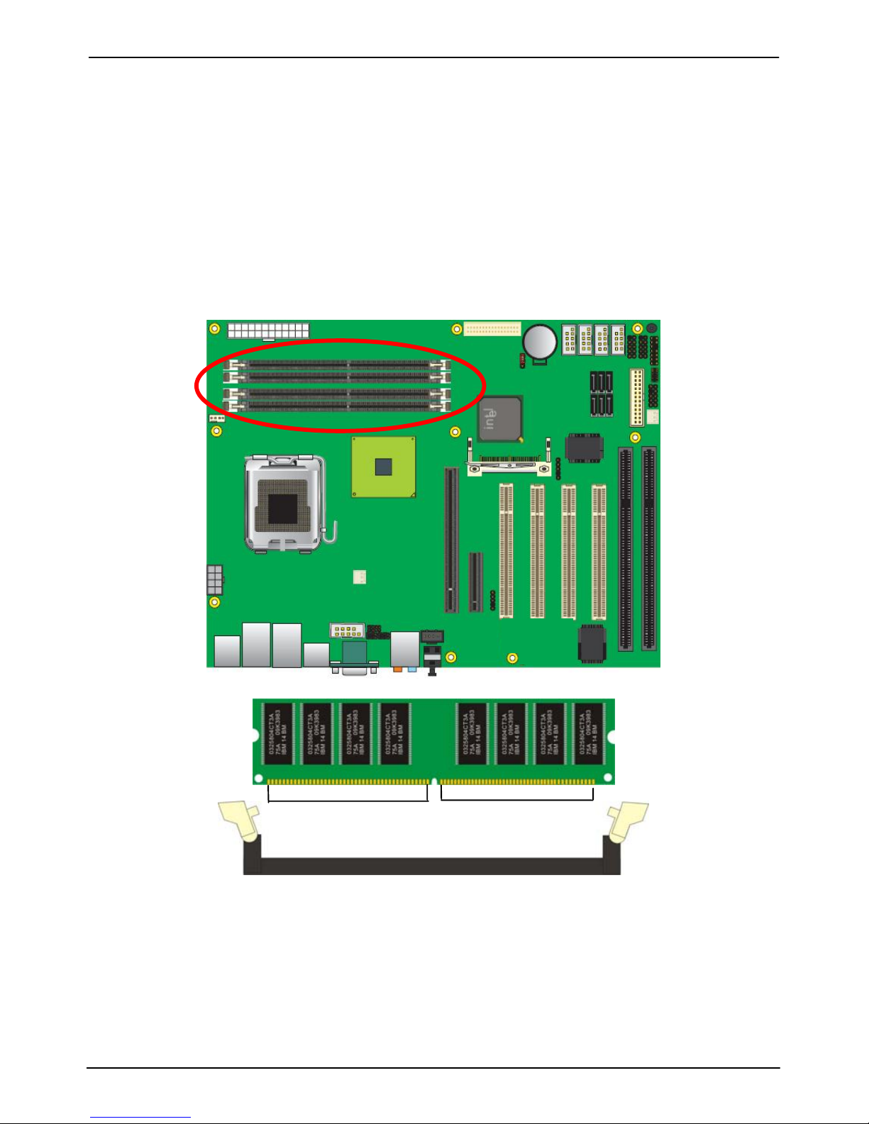
2.4.2 <Memory installation>
2807770 has four 240-pin DDR2 DIMM support up to 8GB of memory capacity. The memory
frequency supports 533/667/800 MHz. Only Non-ECC memory is supported. Dual-Channel
technology is supported while applying two modules with A+B channel.
DDRII B2
DDRII B1
DDRII A2
DDRII A1
112-pin
128-pin
Please check the pin number to match the socket side well
before installing memory module.
 Loading...