

Global American 2807680 User Manual

User’s Manual
Mini-ITX-Motherboard-
2807680
Version 1.0, March 2007

Copyrights
This manual is copyrighted and all rights are reserved. It does not allow any non authorization in
copied, photocopied, translated or reproduced to any electronic or machine readable form in
whole or in part without prior written consent from the manufacturer.
In general, the manufacturer will not be liable for any direct, indirect, special, incidental or
consequential damages arising from the use of inability to use the product or documentation, even
if advised of the possibility of such damages. The manufacturer keeps the rights in the subject to
change the contents of this manual without prior notices in order to improve the function design,
performance, quality and reliability. The author assumes no responsibility for any errors or
omissions, which may appear in this manual, nor does it make a commitment to update the
information contained herein.
Trademarks
Intel is a registered trademark of Intel Corporation.
Award is a registered trademark of Award Software, Inc.
All other trademarks, products and or product's name mentioned herein are mentioned for
identification purposes only, and may be trademarks and/or registered trademarks of their
respective companies or owners.
2807680 User’s Manual Packing List
3
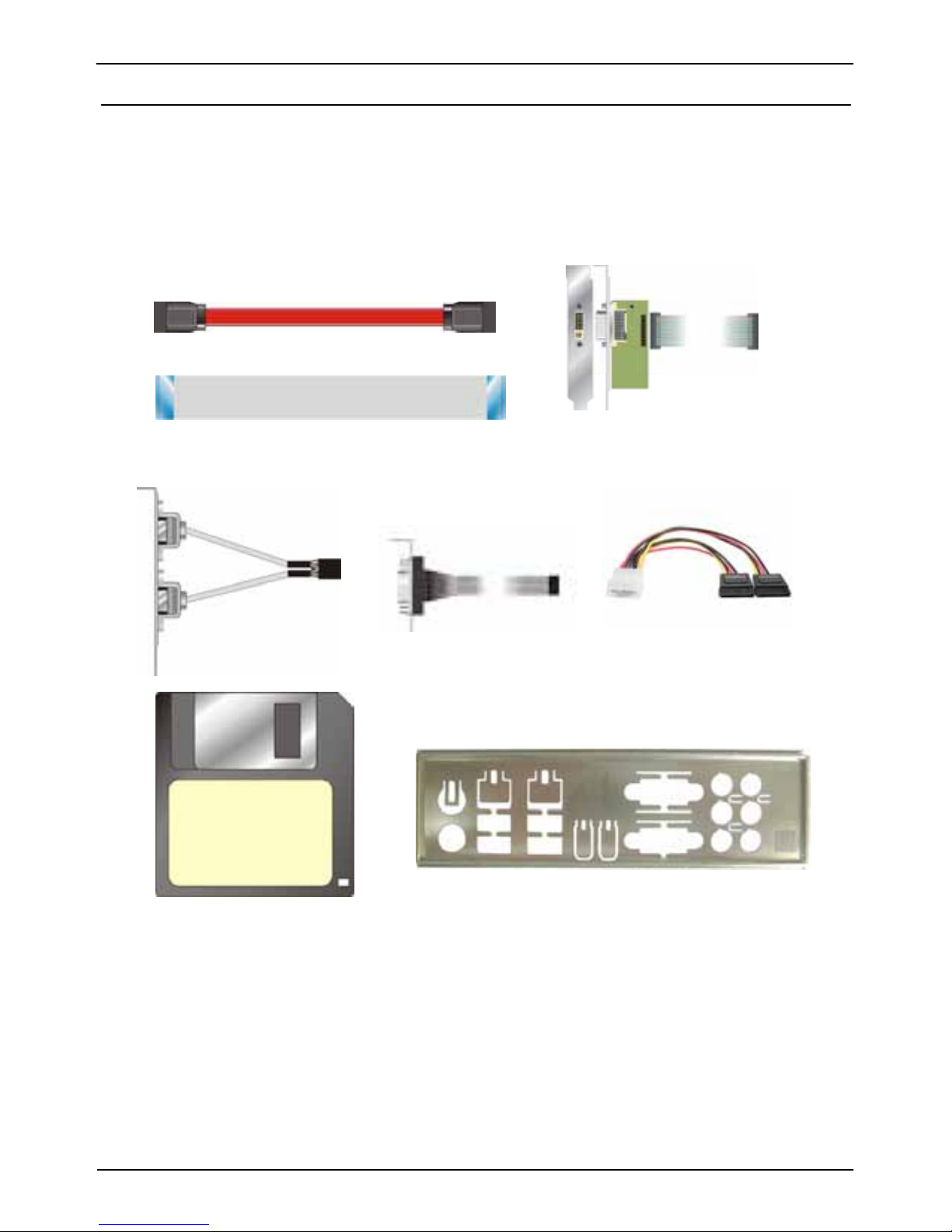
Packing List
Please check package component before you use our products.
Hardware:
2807680 Mini-ITX motherboard x 1
Cable Kit:
SATA Cable x 6
DVI module with bracket x 1
(2807680A Only)
26-pin Slim Type Floppy Cable x 1
USB Cable x 1 SATA Power Y Cable x 3
COM Port Cable x 1
I/O Shield x 1

2807680 User’s Manual Index
4
Index
Chapter1 <Introduction>
............................................................7
1.1 <Product Overview> .............................................................................................7
1.2 <Product Specification>........................................................................................8
1.3 <Block Diagram> ................................................................................................10
1.4 <Mechanical Drawing > ......................................................................................11
Chapter 2 <Hardware Setup>.................................................12
2.1 <Connector Location> .........................................................................................12
2.2 <Jumper Reference> ..........................................................................................13
2.3 <Connector Reference>......................................................................................14
2.3.1 <Internal Connectors> ..............................................................14
2.3.2 <External Connectors> .............................................................14
2.4 <CPU and Memory Setup>.................................................................................15
2.4.1 <CPU installation>...................................................................15
2.4.2 <Memory installation>..............................................................16
2.5 <CMOS Setup>...................................................................................................17
2.6 <Serial ATA installation> ......................................................................................18
2.7 <Floppy Installation>...........................................................................................19
2.8 <LAN installation>...............................................................................................20
2.9 <Onboard Display Interface>.............................................................................. 21
2.9.1 <Analog Display>....................................................................21
2.9.2 <LVDS Display 2807680B Only >................................................22
2.9.3 <DVI Display 2807680A Only >..................................................26
2.10 <Audio Installation> ..........................................................................................27
2.11 <G PIO interface> ..............................................................................................29
2.12 <IEEE1394 and USB Installation> ....................................................................30
2.13 <Power and Fan Installation> ...........................................................................32
2.14 <Serial Port>.....................................................................................................34

2807680 User’s Manual Index
5
2.15 <Switch and Indicator> .....................................................................................35
Chapter 3 <System Configuration>.......................................37
3.1 <SATA configuration>..........................................................................................37
3.2 <SATA RAID Configuration> ...............................................................................38
3.3 <Audio Configuration> ........................................................................................43
3.4 <Video Memory Setup> ......................................................................................44
3.5 <Display Properties Setting>...............................................................................46
Appendix A <I/O Port Pin Assignment>................................50
A.1 <Serial ATA Port>................................................................................................50
A.2<Floppy Port>...................................................................................................... 50
A.3 <IrDA Port>.........................................................................................................51
A.5 <VGA Port>........................................................................................................51
A.6 <LAN Port> .........................................................................................................52
Appedix B <System Resources>...........................................53
Appendix D <Programming GPIO’s>....................................58
Appendix E <Watch Dog timer Setting >..............................59
Contact Information...................................................................60

2807680 User’s Manual
6
(This Page is Left for Blank)

2807680 User’s Manual Index
7
Chapter1 <Introduction>
1.1 <Product Overview>
2807680 is the motherboard with last Intel desktop technology with Mini-ITX form factor.
Based on Intel® Q965 and ICH8DO, the board integrates a new Core 2 Duo processor
775-pin socket, DDR2 memory socket, Intel® Graphic Media Accelerator 300 0 technology,
Serial ATA II with RAID function for a powerful desktop system.
Intel
® LGA775 processor
The Intel® Core 2 Duo processor now comes with a new form factor with 775-pin PLGA
package, for 533/800/1066MHz front-side-bus, 4MB L2 cache, and for 65nm manufacturing
technology, the PLGA processor without pin header on solder side can make user installing
the processor on the socket easier.
Intel
® Q965 and ICH8DO chipset
The Intel Q965 integrates DDR2 533/800/1066MHz for memory, and Graphic Media
Accelerator (GMA) 3000 technology for new graphic eng ine. It can provide up t o 384MB of
frame buffer when you install over 1GB of system memory. The ICH8DO integrates with up
to 6 USB2.0 interfaces , and serial ATA II interface with RAID function.
Flexible Extension Interface
The board provides one PCI-slot for graphics card, it also can support PCI-slot for LAN card
or other devices. The board also provides mini-PCI socket.

2807680 User’s Manual Introduction
Product Specification 8
1.2 <Product Specification>
General Specification
Form Factor Mini-ITX motherboard
CPU
Intel® Core 2 Duo / Pentium 4 / Pentium D / Celeron 440
LGA775 Processor
Package type: PLGA 775
Front side bus: 533/800/1066MT/s (133/200/266MHz x 4)
Intel® Hy
per-Threading Technology and Dual co
re supported
Memory 2 x 240-pin DDR2 533/667/800MHz SDRAM up to 3GB
Unbufferred, none-ECC memory supported only
Chipset Intel® Q965 (Northbridge) and ICH8DO (Southbridge)
BIOS Phoenix-Award v6.00PG 8Mb SPI flash BIOS
Green Function Power saving mode includes doze, standby and suspend modes.
ACPI version 1.0 and APM version 1.2 compliant
Watchdog Timer System reset programmable watchdog timer with 1 ~ 255
sec./min. of timeout value
Real Time Clock Intel® ICH8DO built-in RTC with lithium battery
Serial ATAII Intel® ICH8DO integrates 4 Serial ATA II interface
RAID 0, 1,5,10 Intel Matrix Storage Technology
supported
Multi-I/O Port
Chipset Intel® 82801HDO( ICH8DO) with Winbond® W83627DHG
controller
Serial Port One external RS-232 and one internal RS232/422/485 serial ports
USB Port Six Hi-Speed USB 2.0 ports with 480Mbps of transfer rate
IEEE1394 Two IEEE1394 connectors on rear I/O panel
Floppy Port One slim type Floppy port
IrDA Port One IrDA compliant Infrared interface supports SIR
K/B & Mouse External PS/2 keyboard and mouse ports on rear I/O panel
GPIO One 12-pin Digital I/O connector with 8-bit programmable I/O
interface
Smart Fan One CPU fan connectors for fan speed controllable
VGA Display Interface
Chipset Intel® Q965 GMA3000 (Graphic Memory Controller Hub)
Frame Buffer Up to 384MB shared with system memory
Display Type CRT, LCD monitor with analog display
Onboard 18/24-bit dual channel LVDS interface (2807680B Only)
Onboard DVI interface (2807680B Only)
Connector External DB15 female connector on rear I/O panel
Onboard 40-pin LVDS connector(2807680B Only)
Onboard 26-pin DVI Connector (2807680A Only)

2807680 User’s Manual Index
Product Specification 9
Ethernet Interface
Controller Two Intel 82573L Gigabit Ethernet controller
Type Triple speed 10/100/1000Base-T
Auto-switching Fast Ethernet
Full duplex, IEEE802.3U compliant
Connector Two External RJ45 connectors with LED on rear I/O panel
Audio Interface
Chipset Intel® ICH8DO with Realtek ALC888HD Audio
Intel High Definition Audio compliance
Interface 7.1 channels sound output
Connector External six phone jack for 7.1 channel audio on rear I/O panel
External SPDIF connector on rear I/O panel
Internal 10-pin header for line-in/-out, MIC-in, 4-pin header for CD-IN
Expansive Interface
Mini PCI One Mini-PCI socket TYPE III A (32-bit, 33MHz)
Power supply: +3.3V, +5V
Power and Environment
Power
Requirement
Standard ATX 24-pin (20-pin is compatible) power supply
Additional +12V 4-pin power connector
Dimension 170 (L) x 170 (H) mm
Temperature Operating within 0 ~ 60oC (32 ~ 140oF)
Storage within -20 ~ 85
o
C (-4 ~ 185oF)
Ordering Code
2807680A Onboard VGA, 2 x Gigabit LAN, Mini-PCI , PCI, 6 x SATA, HD Audio,
IEEE1394, 1 X IrDA, DVI
2807680B Onboard VGA, 2 x Gigabit LAN, Mini-PCI , PCI, 6 x SATA, HD Audio,
IEEE1394, 1 X IrDA, LVDS
The specifications may be different as the actual production.
For further product information please visit the website at http://www.globalamericaninc.com
2807680 User’s Manual Introduction
Block Diagram 10
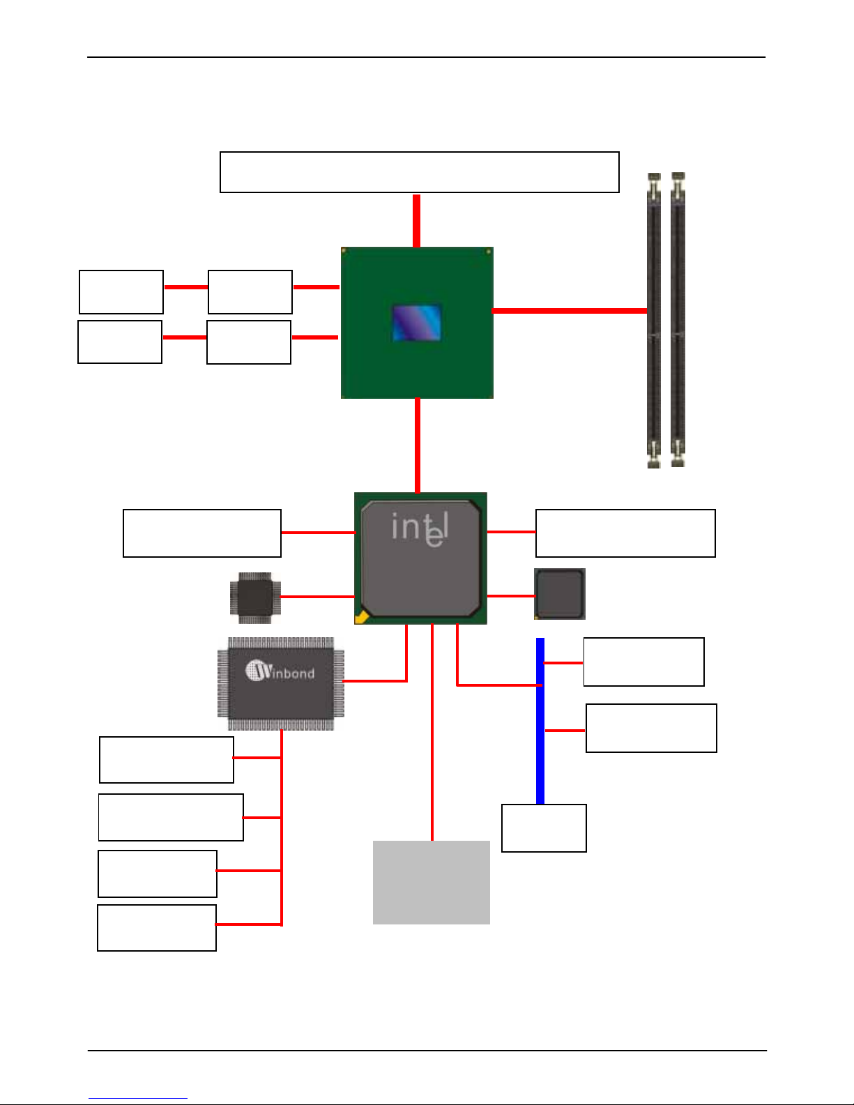
1.3 <Block Diagram>
Intel Core 2 Duo with 775 pin PLGA processor
Intel Q965
2 x 240-pin DDR2
533/667/800MHz
up to 3GB
PCI bus
Mini-PCI slot
2 x Serial ports
1 x Floppy port
8-bit GPIO
6 x USB2.0 ports
Intel 82573L
2 x GLAN
2 X IEEE1394
HD Audio
ICH8DO
LVDS
DVI
CH7307
CH7308
SPI
BIOS
IrDA
6 x Serial ATAII ports
2807680 User’s Manual Introduction
Mechanical Drawing 11
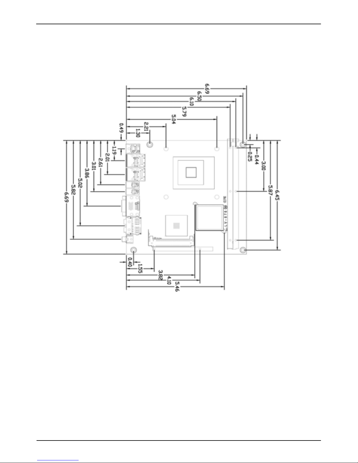
1.4 <Mechanical Drawing >
2807680 User’s Manual Hardware Setup
Connector Location 12
Chapter 2 <Hardware Setup>
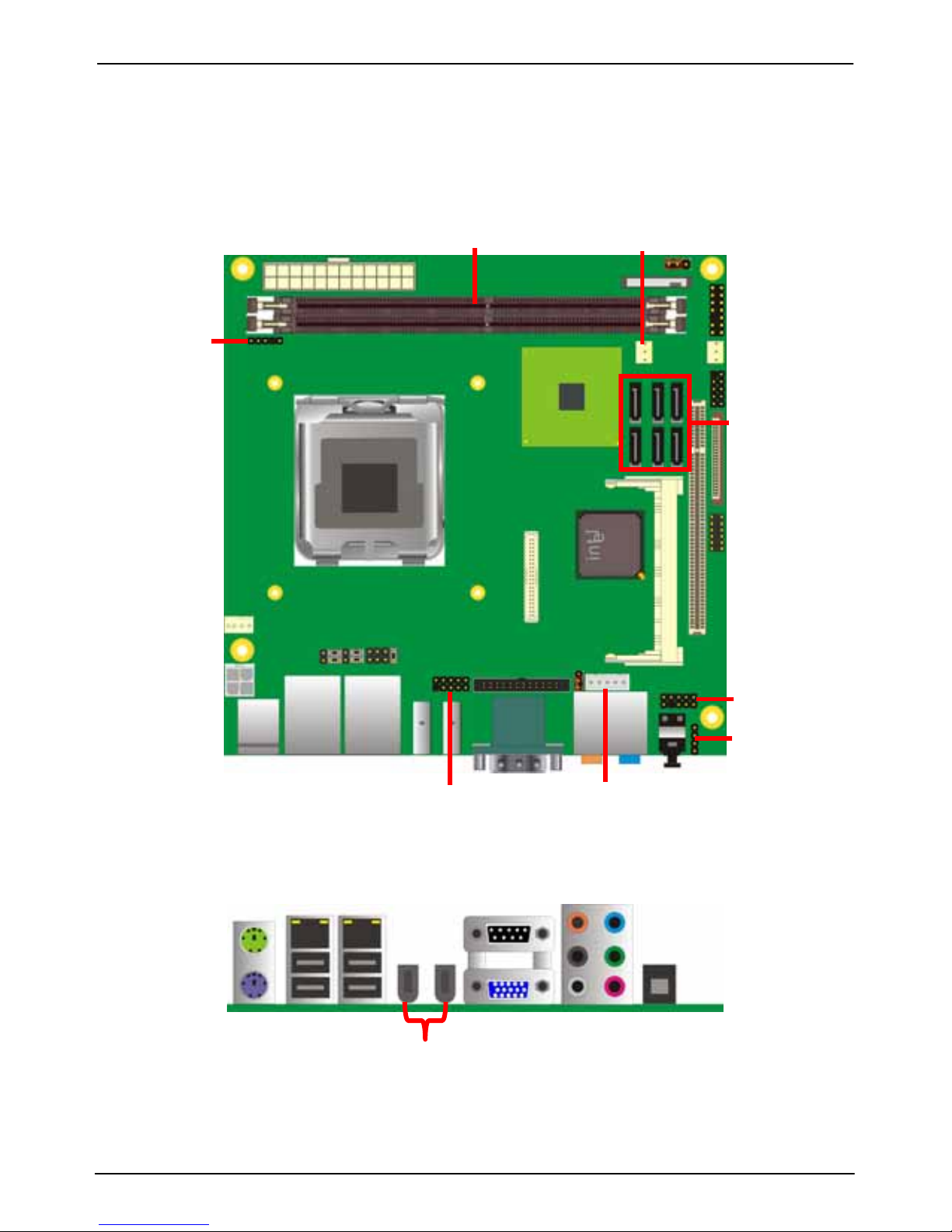
2.1 <Connector Location>
PS2
NBFAN
CN_IR
A
TX
DDRII1/2
JFRNT
SYSFAN
FDD
CN_USB
S_ATA1~6
CN_DIO
CN_LVDS
PCI
CPUFAN
Mini-PCI
CN_DVI
CN_12V
CN_IN
V
CN_AUDIO
CDIN
CN_COM2
USB_RJ45_1/2
CRT+COM1
Audio
SPDIF
1394_1/2
2807680 User’s Manual Hardware Setup
Conne
ctor Reference 14
2.3 <Connector Reference>
2.3.1 <Internal Connectors>
Connector Function Remark
CPU LGA775 CPU socket
DDRII1/2 240 -pin DDR2 SDRAM DIMM socket
FDD 26-pin slim type floppy connector
S_ATAII1/2/3/4/5/6 7-pin Serial ATA II connector
ATX 24-pin power supply connector
CN_12V 4-pin +12V additional power supply connector
CN_AUDIO 5 x 2-pin audio connector
CDIN 4-pin CD-ROM audio input connector
CN_DIO 6 x 2-pin digital I/O connector
CN_USB 10-pin USB connector
CPUFAN 4-pin CPU cooler fan connector
SYSFAN 3-pin system cooler fan connector
NBFAN 3-pin Northbridge cooler fan connector
CN_IR 5-pin IrDA connector
CN_INV 5-pin LCD inverter connector 2807680B
CN_LV DS 20 x 2-pin LVDS connector 2807680B
JFRNT 14-pin front panel switch/indicator connector
PCI1 120-Pin PCI socket
Mini-PCI 2 x Mini-PCI socket
CN_DVI 26-Pin connector 2807680A
CN_COM2 5 x 2-pin com connector
2.3.2 <External Connectors>
Connector Function Remark
PS2 PS/2 Keyboard/Mouse connector
CRT+COM1 DB15 VGA + Serial port connector
USB_RJ45_1/2 Dual USB and one RJ45 LAN Port
1394_1/2 IEEE1394 port
AUDIO Audio connectors
SPDIF SPDIF digital audio output connector
2807680 User’s Manual Hardware Setup
CPU installation 15
2.4 <CPU and Memory Setup>
2.4.1 <CPU installation>
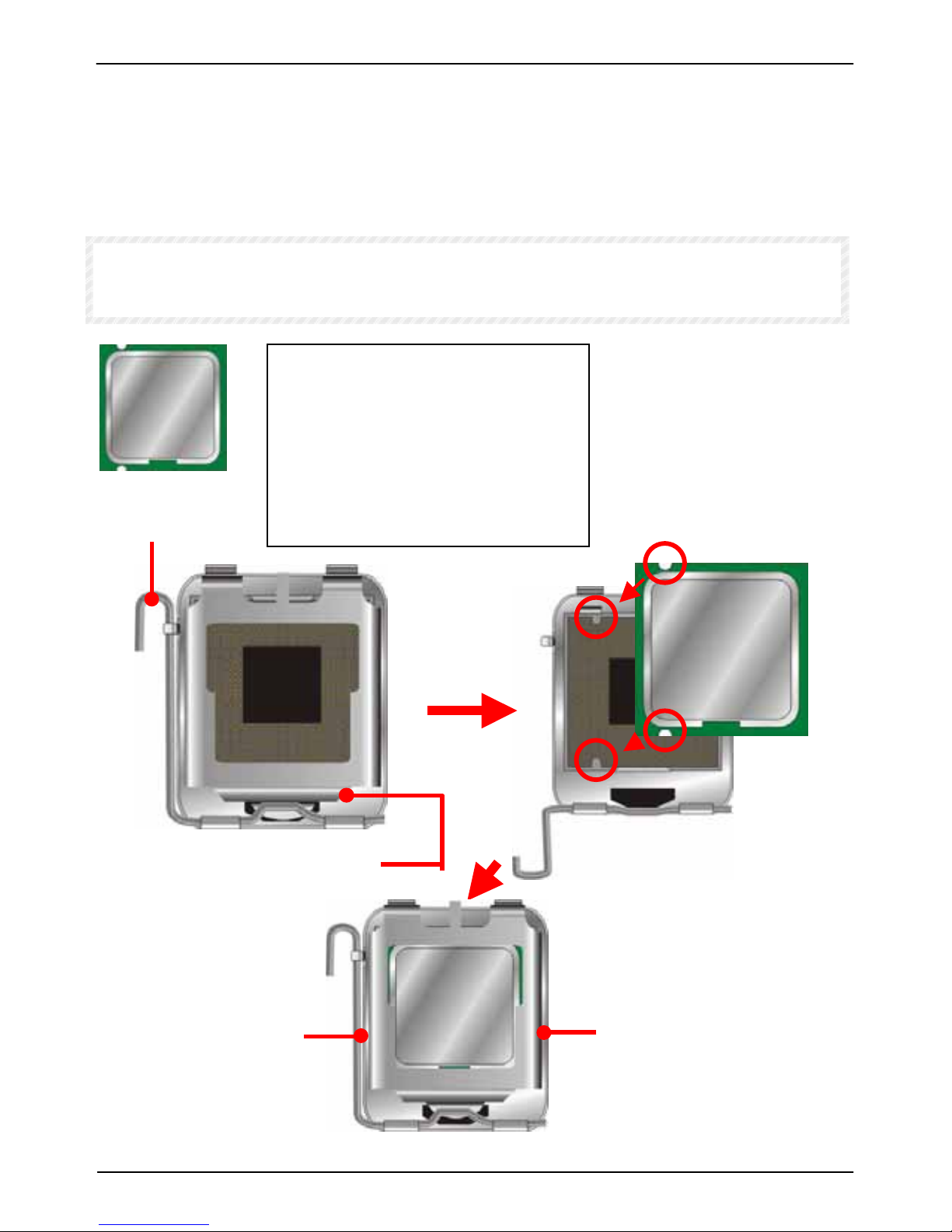
2807680 has a LGA775 CPU socket onboard; please check following steps to install the
processor properly.
Attention If 2807680 need RMA please Keep CPU socket cover on the CPU Socket.
Warring If CPU Socket internal Pin damage We could not provide warranty.
Intel® Core 2 Duo processor
Package type: 775 pin PLGA
L2 Cache: 4 MB
FSB: 533/800/1066MHz (266MHz x 4)
Manufacturing: 65nm
Intel Hyper Threading Technology
and Core 2 Duo supported
Check point
1. Lift this bar
2. Uncover this plate
3. Place the CPU on the top of
the pins
3. Cover this plate
4. Lock this bar
Notice: Please place the CPU on the pins tenderly to avoid bending the pins
2807680 User’s Manual Hardware Setup
Memory Installation 16
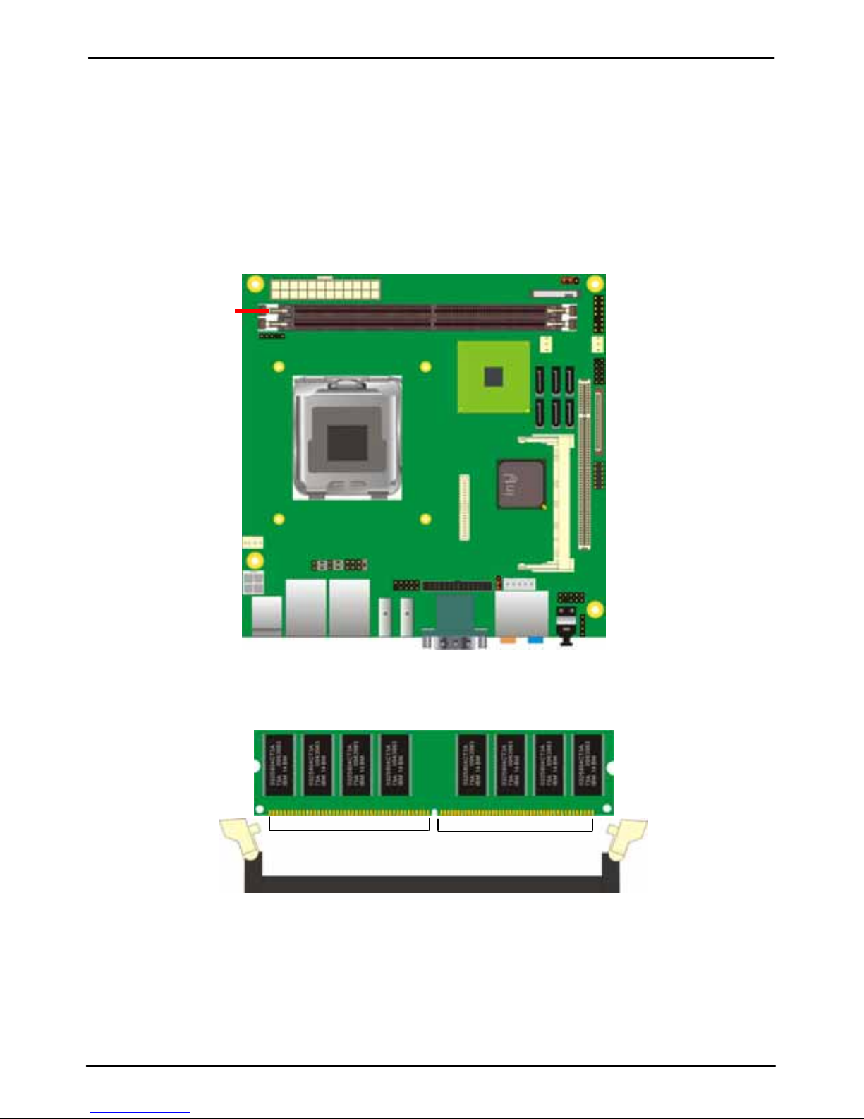
2.4.2 <Memory installation>
2807680 has two 240-pin DDR2 DIMM support up to 3GB of memory capacity. The memory
frequency supports 533/667/800MHz . Only Non-ECC memory is supported.
DDRII1/2
112-pin128-pin
Please check the pin number to match the socket side well
before installing memory module.
2807680 User’s Manual Hardware Setup
CMOS Setup 17
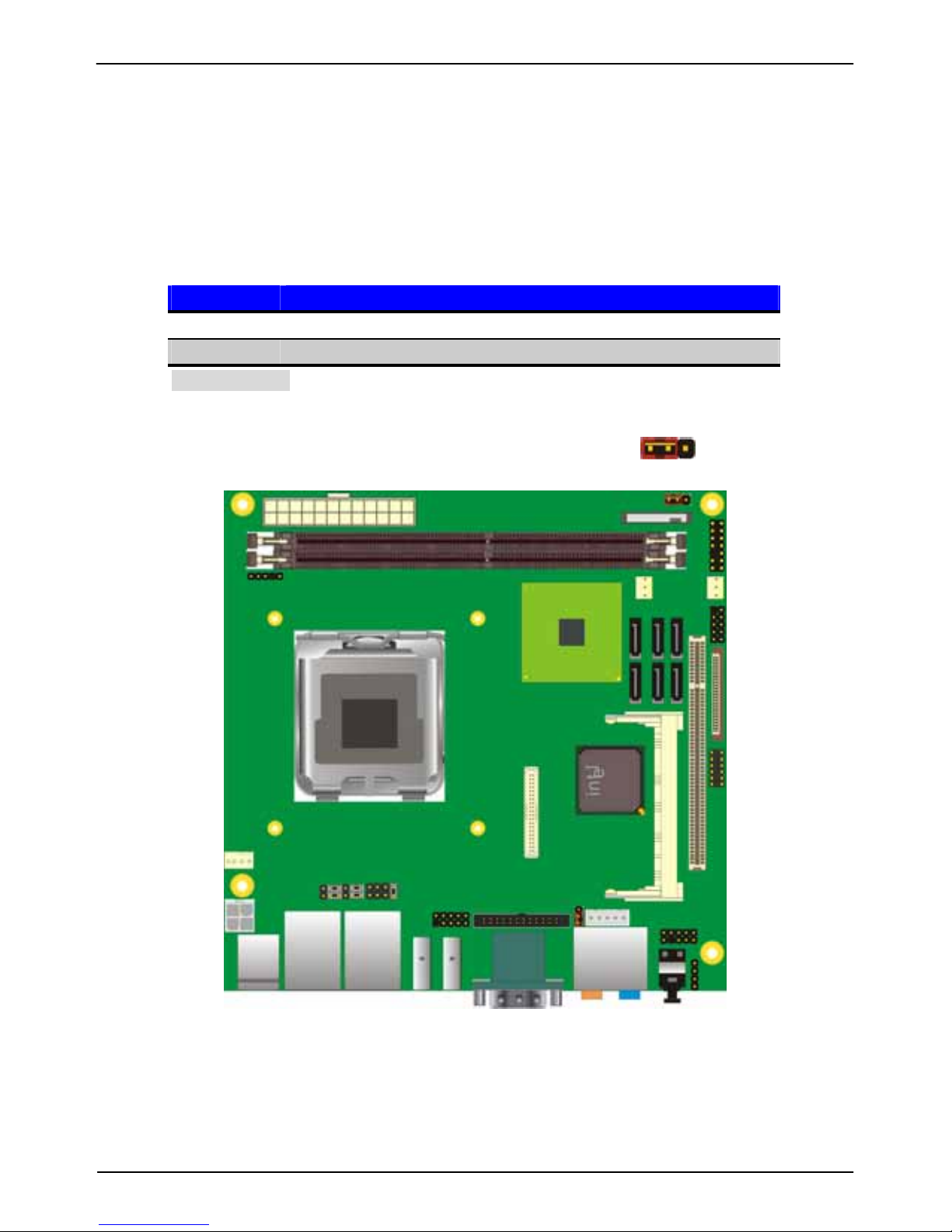
2.5 <CMOS Setup>
The board’s data of CMOS can be setting in BIOS. If the board refuses to boot due to
inappropriate CMOS settings, here is how to proceed to clear (reset) the CMOS to its
default values.
Jumper: JRTC
Type: Onboard 3-pin jumper
JRTC Mode
1-2 Clear CMOS
2-3 Normal Operation
Default setting
13
JRTC
 Loading...