

Global American 2807616 User Manual

2807616
2807616
28076162807616
AMD Geode NX
Mini-ITX Motherboard
USER’S MANUAL
USER’S MANUAL
USER’S MANUALUSER’S MANUAL
Version 1.0

Acknowledgments
Award is a registered trademark of Award Software International,
Inc.
PS/2 is a trademark of International Business Machines
Corporation.
AMD is a trademark of Advanced Micro Devices, Inc.
Microsoft Windows is a registered trademark of Microsoft
Corporation.
Winbond is a registered trademark of Winbond Electronics
Corporation.
All other product names or trademarks are properties of their
respective owners.
ii
2807616 User’s Manual

Table of Contents
Introduction
Product Description .............................................................1
Checklist ..............................................................................2
2807616 Specifications .......................................................3
Board Dimensions ...............................................................4
Installations
Installing the CPU ...............................................................6
Installing the Memory .........................................................7
Setting the Jumpers .............................................................8
Connectors on 2807616.....................................................11
BIOS Setup
Drivers Installation
SIS 741CX Chipset VGA Driver ......................................42
SIS Chipset Ethernet Driver ..............................................45
Realtek Gigabit Ethernet Driver ........................................47
Realtek AC97 Codec Driver..............................................48
Appendix
....................................................... 1
....................................................... 5
...................................................... 21
...................................... 41
........................................................... 50
A. I/O Port Address Map...................................................50
B. Interrupt Request Lines (IRQ) ......................................51
2807616 User’s Manual iii
iv
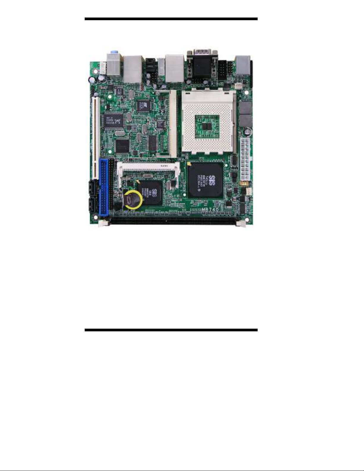
THE 2807616 MINI ITX MOTHERBOARD
2807616 User’s Manual

INTRODUCTION
Introduction
Product Description
The 2807616 Mini ITX board incorporates a Socket A processor socket that
supports AMD Geode NX series processors that support processor speed up to
1.4GHz. With the SIS 741CX chipset, it delivers maximum performance for
demanding thin client or embedded applications that require silent system
operation. With a higher processor speed and active cooling, it is best suited for
demanding applications such as graphics and point of sales systems. The board
comes with integrated chipset VGA and Ethernet controllers. Optionally
provided is a Realtek Gigabit Ethernet and daughter cards for TV out/TMDS/
LVDS/CRT2 interface.
Features
Socket A for AMD Geode NX processor
Up to 1.4GHz speed, 133MHz FSB
DDR DIMM x 1, max. 1GB, DDR266/333
Onboard 10/100 and Optional Realtek 8110S Gigabit LAN
Integrated SiS 741CX CRT VGA
Optional CRT2/DVI, optional LVDS/TV out
2 x SATA, 6 x USB 2.0, 2 x COM, watchdog timer
Digital I/O, optional 1394, 1x PCI, 1x Mini PCI
Dimensions of the board are 170mm x 170mm.
2807616 User’s Manual 1

INTRODUCTION
Checklist
Your 2807616 package should include the items listed below.
•••• The 2807616 Pentium
•••• This User’s Manual
•••• 1 CD containing chipset drivers and flash memory utility
•••• Cable kit (40-pin IDE, 44-pin IDE, Serial port, Serial ATA)
440
®
M Mini-ITX motherboard
2
2807616 User’s Manual
2807616 Specifications
[
Features
System
CPU
System Memory
System Chipset
BIOS
Watchdog Timer
SSD
H/W Monitor
Expansion Slot
Graphics
VGA Controller
VGA Memory
LCD / TV-out / DVI /
CRT2
Ethernet
Controller
Connector
Multi I/O
Chipset
USB
Audio
Others
Mechanical and Environmental
Dimensions
Socket A for AMD Geode NX processor
Up to 1.4GHz speed, 133MHz FSB
DDR DIMM x 1, max. 1GB, DDR266/333
Onboard 10/100 and Optional Realtek 8110S Gigabit LAN
Integrated SiS 741CX CRT VGA
Optional CRT2/DVI, optional LVDS/TV out
2 x SATA, 6 x USB 2.0, 2 x COM, watchdog timer
Digital I/O, optional 1394, 1x PCI, 1x Mini PCI
Socket A (462-pin) for AMD Geode, up to 1.4GHz
(NX1250 = 667MHz, NX1500 = 1GHz, NX1250 =1.4GHz)
DDR DIMM x 1, max. 1GB, DDR333
SiS 741CX + SiS 964
Award 4Mbit
256 levels
Optional CF socket (on solder side via IDE2)
Yes
1 PCI, 1 Mini PCI, 1 MicroAGP
SiS 741CX integrated for CRT
Shared memory
Max. 64MB
Optional SiS 302LV MicroAGP card (IBA140-302)
supports 18/24-bit dual channel LVDS and TV out;
Optional SiS 301 MicroAGP card (IBA140-301)
supports DVI/CRT2 interface
SiS 964 built-in 10/100 and Optional Realtek
RTL8110S-32 Gigabit LAN
Two RJ-45 on board (optional for GB LAN)
SiS 964, ITE 8705
2x IDE (UDMA33/66/100), 1x FDD, 1x KB, 1x Mouse; 2x
RS-232, 2x SATA
4 ports on board
Pin header for 2 additional ports (USB 2.0)
SiS 964 built-in audio + AC97 codec, SPDIF support;
2W+2W volume amplifier
1394, ATX power connector
170mm x 170mm
INTRODUCTION
2807616 User’s Manual 3
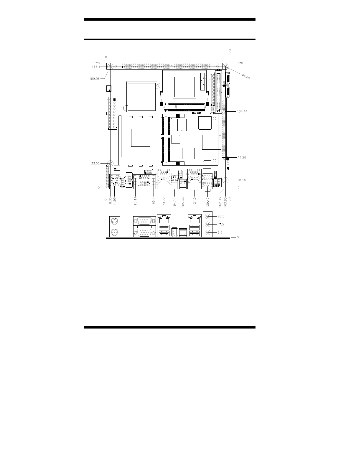
INTRODUCTION
Board Dimensions
4
2807616 User’s Manual

INSTALLATIONS
Installations
This section provides information on how to use the jumpers and
connectors on the 2807616 in order to set up a workable system. The
topics covered are:
Installing the CPU ........................................................................ 6
Installing the Memory................................................................... 7
Setting the Jumpers.......................................................................8
Connectors on 2807616 .............................................................. 11
2807616 User’s Manual 5
INSTALLATIONS
Ensure that the CPU heat sink and the CPU top surface are in
uld
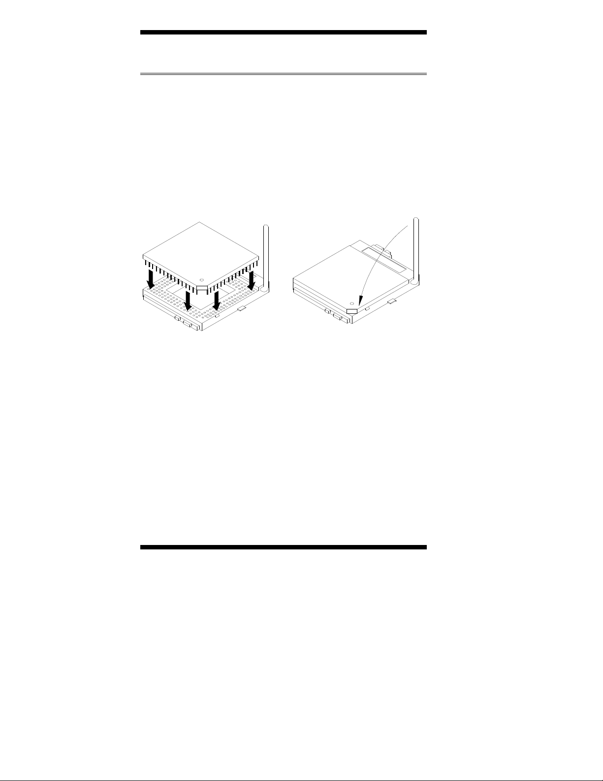
Installing the CPU
The 2807616 board supports a Socket A processor socket for AMD NX
Series processors.
The Socket A processor socket comes with a lever to secure the
processor. Raise this lever to about a 90° angle to allow the insertion of
the processor. Place the processor into the socket by making sure the
notch on the corner of the CPU corresponds with the notch on the inside
of the socket. Once the processor has slide into the socket, return the
lever to the lock position. Refer to the figures below.
After you have installed the processor into the socket, check if the
jumpers for the CPU type and speed are correct.
NOTE:
total contact to avoid CPU overheating problem that wo
cause your system to hang or be unstable.
6
2807616 User’s Manual
INSTALLATIONS
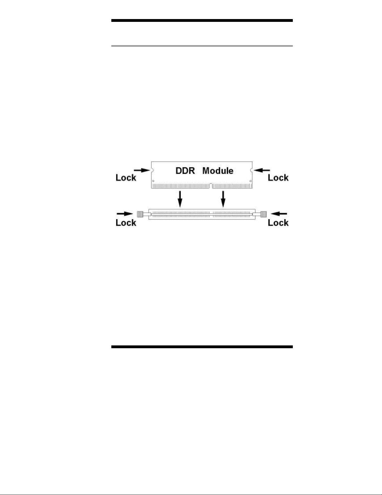
Installing the Memory
The 2807616 board supports one DDR memory socket for a maximum
total memory of 1GB in DDR memory type.
Installing and Removing Memory Modules
To install the DDR modules, locate the memory slot on the board and
perform the following steps:
1. Hold the DDR module so that the key of the DDR module align with
those on the memory slot.
2. Gently push the DDR module in an upright position until the clips of
the slot close to hold the DDR module in place when the DDR module
touches the bottom of the slot.
3. To remove the DDR module, press the clips with both hands.
2807616 User’s Manual 7

INSTALLATIONS
Setting the Jumpers
Jumpers are used on 2807616 to select various settings and features
according to your needs and applications. Contact your supplier if you
have doubts about the best configuration for your needs. The following
lists the connectors on 2807616 and their respective functions.
Jumper Locations on 2807616 ........................................................9
JP8: CompactFlash Slave/Master Selection ..................................10
JP9: 1394 EPROM Write Selection ..............................................10
JP12: Clear CMOS Setting............................................................10
JP14: RTL8110S-32 LAN Enable / Disable .................................10
8
2807616 User’s Manual
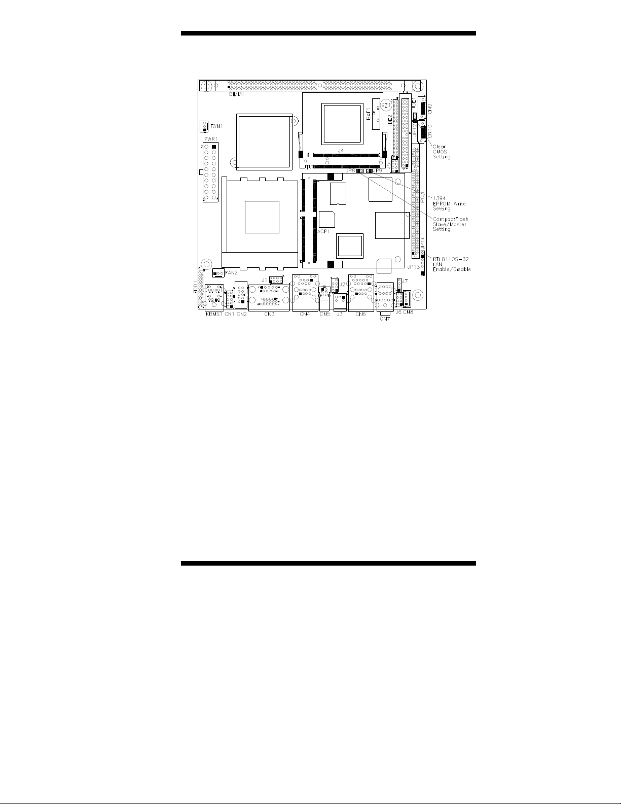
Jumper Locations on 2807616
INSTALLATIONS
Jumpers on 2807616 ........................................................................ Page
JP8: CompactFlash Slave/Master Selection .........................................10
JP9: 1394 EPROM Write Selection .....................................................10
JP12: Clear CMOS Setting................................................................... 10
JP14: RTL8110S-32 LAN Enable / Disable ........................................10
2807616 User’s Manual 9
INSTALLATIONS
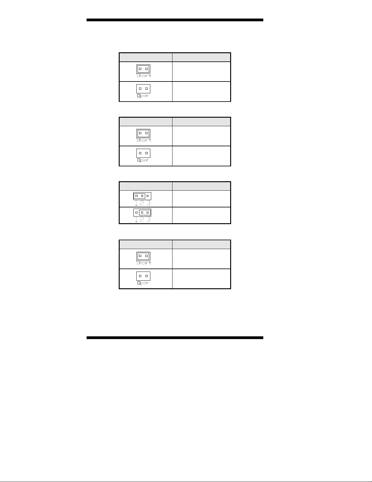
JP8: CompactFlash Slave/Master Selection (option)
Remarks: The CF socket and its corresponding slave/master Selection is
optional.
JP8 CF Setting
Master
Slave
JP9: 1394 EPROM Write Selection
JP9 1394 EPROM
For EPROM Write
Normal
JP12: Clear CMOS Setting
JP12 Setting
Normal
Clear CMOS
JP14: RTL8110S-32 LAN Enable / Disable
JP14 Gigabit LAN
Disable
Enable
[
10
2807616 User’s Manual

INSTALLATIONS
Connectors on 2807616
The connectors on 2807616 allow you to connect external devices such
as keyboard, floppy disk drives, hard disk drives, printers, etc. The
following table lists the connectors on 2807616 and their respective
functions.
Connector Locations on 2807616 .................................................12
KBMS1: PS/2 Keyboard and PS/2 Mouse Connectors................. 13
CN3: COM1 and VGA Connector ................................................13
CN4: 10/100 RJ-45 and USB1/2 Ports ......................................... 14
CN5: 1394 Connector ...................................................................14
J3: SPDIF Out Connector ............................................................. 14
CN6: GbE RJ-45 and USB3/4 Ports .............................................14
CN7: Audio Connector .................................................................14
PWR1: ATX Power Supply Connector......................................... 14
FAN1: System Fan Power Connector ...........................................15
FAN2: CPU Fan Power Connector ...............................................15
IDE1, IDE2: 40-pin and 44-pin IDE Connectors..........................15
FDD1: Floppy Drive Connector.................................................... 16
CN1: Digital I/O ........................................................................... 17
J1: USB5/6 Port Pin Header ......................................................... 17
CN2: COM2 Serial Port ................................................................ 17
J2: 1394 Pin Header......................................................................17
J4: Mini PCI Connector ................................................................17
J5: System Function Connector.....................................................18
J6: Front Audio Connector............................................................18
J7: CD-In Pin Header.................................................................... 18
CN8: Speaker Connector .............................................................. 18
CN9, CN10: Serial ATA Connectors ............................................18
CN11: Compact Flash Connector .................................................19
J13: IrDA Connector..................................................................... 19
PCI1: PCI Slot (supports 2 Master) ..............................................19
AGP1: MicroAGP Socket ............................................................. 19
2807616 User’s Manual 11
INSTALLATIONS
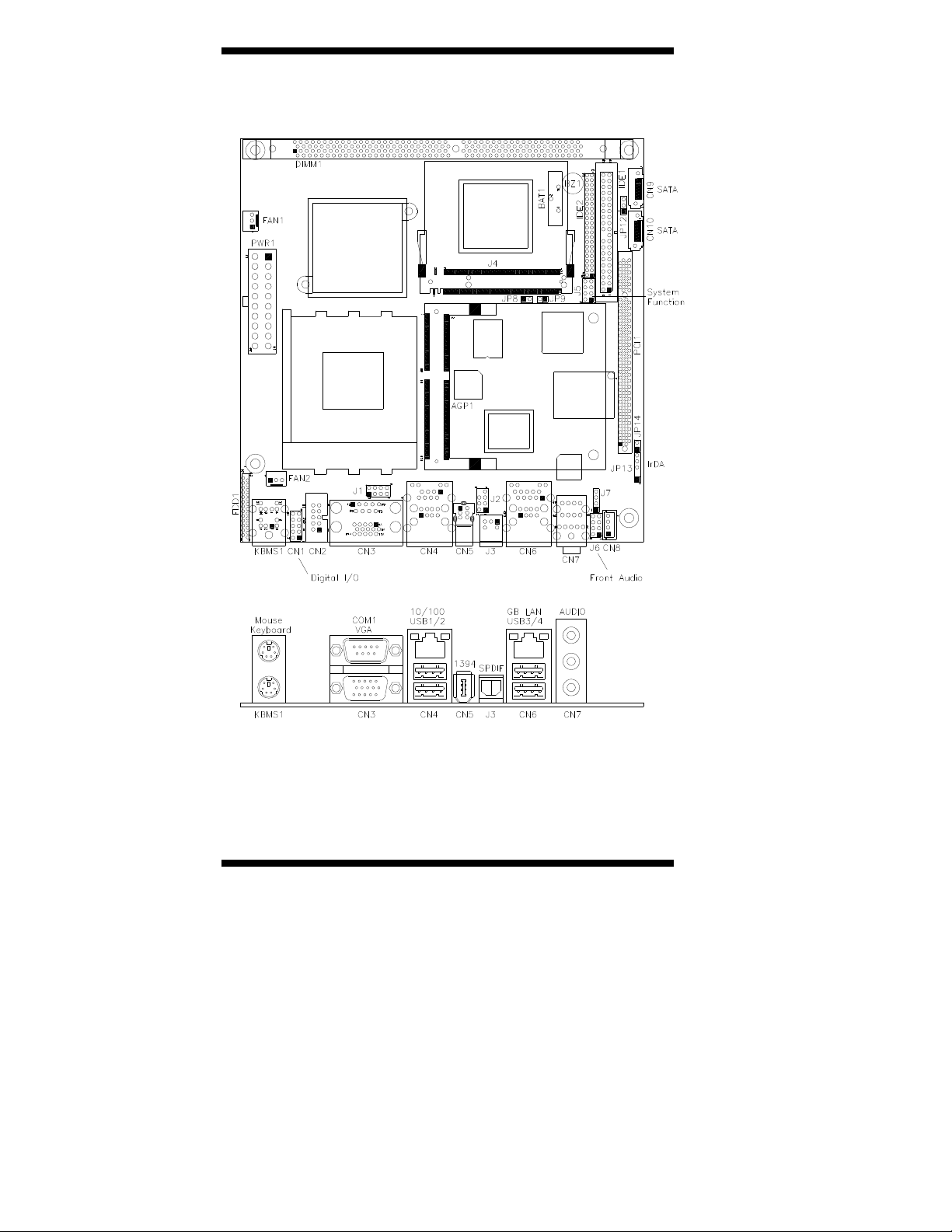
Connector Locations on 2807616
Remarks: GB LAN and 1394 are options found on 2807616 only.
12
2807616 User’s Manual
INSTALLATIONS
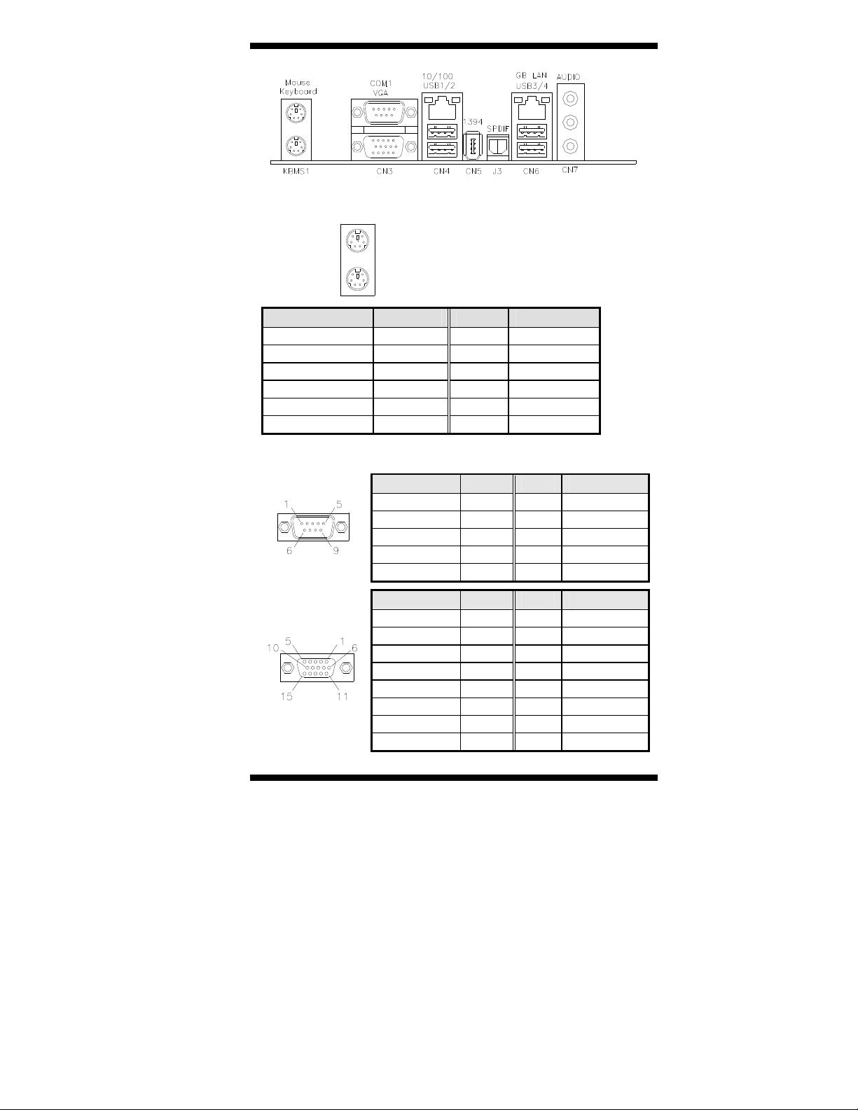
KBMS1: PS/2 Keyboard and PS/2 Mouse Connectors
PS/2 Mouse
PS/2 Keyboard
Signal Name Keyboard Mouse Signal Name
Keyboard data 1 1 Mouse data
N.C. 2 2 N.C.
GND 3 3 GND
5V 4 4 5V
Keyboard clock 5 5 Mouse clock
N.C. 6 6 N.C.
CN3: COM1 and VGA Connector
[
Signal Name Pin # Pin # Signal Name
DCD 1 6 DSR
RXD 2 7 RTS
TXD 3 8 CTS
[[[[
DTR 4 9 RI
GND 5 10 Not Used
Signal Name Pin # Pin # Signal Name
Red 1 2 Green
Blue 3 4 N.C.
GND 5 6 GND
GND 7 8 GND
N.C. 9 10 GND
N.C. 11 12 N.C.
HSYNC 13 14 VSYNC
NC 15
2807616 User’s Manual 13
 Loading...