

Global American 2807610 User Manual

User’s Manual
Mini-ITX Motherboard 2807610

Copyrights
This manual is copyrighted and all rights are reserved. It does not allow any non authorization in
copied, photocopied, translated or reproduced to any electronic or machine readable form in
whole or in part without prior written consent from the manufacturer.
In general, the manufacturer will not be liable for any direct, indirect, special, incidental or
consequential damages arising from the use of inability to use the product or documentation, even
if advised of the possibility of such damages. The manufacturer keeps the rights in the subject to
change the contents of this manual without prior notices in order to improve the function design,
performance, quality and reliability. The author assumes no responsibility for any errors or
omissions, which may appear in this manual, nor does it make a commitment to update the
information contained herein.
Trademarks
Intel is a registered trademark of Intel Corporation.
Award is a registered trademark of Award Software, Inc.
All other trademarks, products and or product's name mentioned herein are mentioned for
identification purposes only, and may be trademarks and/or registered trademarks of their
respective companies or owners.
2807610 User’s Manual
Packing List
Please check the package before you starting setup the system
Hardware:
2807610 series mother board x 1
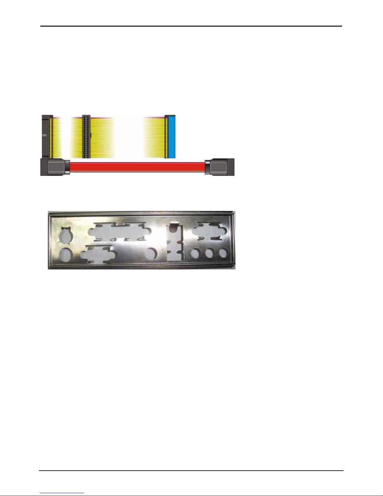
Cable Kit:
40-pin AT A100 IDE flat cable x 1
Serial A T A ribbon cable x 1
I/O Shield x 1
3

2807610 User’s Manual
Index
Chapter 1 <Introduction> ..................................................................................... 7
1.1 <Product Overview>................................................................................. 7
1.2 <Product Specification> ........................................................................... 8
1.3 <Mechanical Drawing>........................................................................... 10
1.4 <Block Diagram>.................................................................................... 11
Chapter 2 <Hardware Setup>............................................................................. 12
2.1 <Connector Location> ............................................................................ 12
2.2 <Jumper Reference> ............................................................................. 13
2.3 <Connector Reference> ......................................................................... 14
2.3.1 <Internal Connector>.................................................................. 14
2.3.2 <External Connector>................................................................. 14
2.4 <CPU and Memory Setup> .................................................................... 15
2.4.1< CPU> ........................................................................................ 15
2.4.2 <Memory> .................................................................................. 15
2.5 <CMOS Setup> ...................................................................................... 16
2.6 <Enhanced IDE & CF Interface>............................................................ 17
2.7 <Serial ATA Interface> ........................................................................... 18
2.8 <LAN Interface> ..................................................................................... 19
2.9 <Onboard Display Interface> ................................................................. 20
2.9.1 <Analog VGA Interface> ............................................................ 20
2.10 <Onboard Audio Interface>.................................................................. 21
2.11 <Power and F an Connector> ............................................................... 22
2.11.1 <Power Input> .......................................................................... 22
2.11.2 <Fan Connector>...................................................................... 22
2.12 <Indicator and Switch>......................................................................... 23
Chapter 3 <System Configuration>................................................................... 25
3.1 <SATA RAID Configuration>.................................................................. 25
4

2807610 User’s Manual
3.2 <Audio Configuration> ........................................................................... 27
3.3 <Display Configuration> ......................................................................... 28
Chapter 4 <BIOS Setup> .................................................................................... 30
Appendix A <I/O Port Pin Assignment> ........................................................... 32
A.1 <IDE Port> ............................................................................................. 32
A.2 <IrDA Port> ............................................................................................ 32
A.3 < VGA Port >.......................................................................................... 33
A.4 <Serial ATA Port> ................................................................................... 33
A.5 <Serial Port> .......................................................................................... 33
A.6 <LAN Port> ............................................................................................ 34
A.7 <PS/2 Keyboard & Mouse Port>............................................................ 34
A.8 <CPU Voltage>…...................................................................................35
A.9<USB Interface>……………………………………………………………..35
Appendix B <Flash BIOS>.................................................................................. 37
B.1 BIOS Auto Flash Tool ...................................................................... 37
B.2 Flash Method................................................................................... 37
Appendix C <System Resources> .................................................................... 39
C.1 < I/O Port Address Map>…… ………………………………………………39
C.2 <Memory Address Map> ....................................................................... 41
C.3 <System I RQ & DMA Resource> .......................................................... 42
C.3.1 <IRQ> ........................................................................................ 42
Contact Information ............................................................................................ 44
5

2807610 User’s Manual
(The Page is Left For Blank)
6

2807610 User’ s M anual Introduction
Chapter 1 <Introduction>
1.1 <Product Overview>
2807610 is the Mini-ITX motherboard based on VIA chipset. It integrates the last VIA
embedded chipset for KN400A with VT8237R, DDR266/333/400 SDRAM, and serial ATA
with RAID to provide the economical em bedded platform.
VIA KN400A & VT8237R Chipset
The board comes with the VIA last embedded chipset of KN400A, supports
DDR266/333/400 SDRAM, integrated the S3 Graphics UniChrome Pro IGP graphics core,
hardware MPEG-2 and MPEG-4 acceleration.
The VT8237R provides the board to support Ultra V-Link (1GB/s) with KN400A, t wo serial
ATA ports with RAID array function, 4 x USB2.0 ports and 5.1 channel AC97 audio.
Multimedia solution
Based on VIA KN400A chipset, the board provides, which supports single independent
display wit h CRT.
LAN Interface
2807610 also comes with one 10/100Mbps LAN interface, support boot-on-LAN and
wake-on-LAN function.
High Speed Hot-plug Interface
Based on VIA VT8237R, the board provides 4 USB2.0 interfaces with up to 480Mbps of
transferring rate.
Expanded UCR for remote Operating SETUP Bios Feature
Expanded Universal Console Redirection (UCR) is a feature for monitoring POST
messages and running Setup and an operation system from a remote serial terminal.
Product Overview 7

2807610 User’ s M anual Introduction
1.2 <Product Specification>
General Specification
Form Factor Mini-ITX motherboard
CPU
AMD Geode NX Processors
NX 1250@6W/1500@6W Processors supported
Fanless with CPU heatsink
Memory 1 x 184-pin DDR 266/333/400 SDRAM up t o 1GB
Unbufferred, none-ECC m emory supported only
Chipset VIA KN400A and VT8237R
BIOS Phoenix-Award v6.00PG 4Mb PnP flash BIOS
Green Function Power saving mode includes doze, standby and suspend modes.
ACPI version 1.0 and APM version 1.2 compliant
Real Time Clock VIA VT8237R built-in RTC with lithium battery
Enhanced IDE Enhanced IDE interface supports dual channels and up to 2
ATAPI devices at Ultra DMA100
One 40-pin onboard
Serial ATA VIA VT8237R integrates 2 Serial ATA interface
RAID 0, 1 array Technology supported
Multi-I/O Port
Chipset VIA VT8237R with Winbond W 83697HF con troller
Serial Port one ext ernal RS-232 serial port on rear I/O panel.
USB Port Four Hi-Speed USB 2.0 ports wi th 480Mbps of transfer rate.
Parallel Port One external parallel port on rear I/O panel.
IrDA Port One Ir DA compliant I nfrared i nterface supports SIR.
K/B & Mouse External PS/2 keyboard and mouse ports on rear I/O panel
Hardware
Monitor
VGA Display Interface
Fan speed, CPU t emperature and voltage m onitoring
Chipset VIA KN400A built-in S3 Graphics UniChrome Pro IGP graphics
core
Core Frequency 200MHz
Memory BIOS selectable 16/32/64MB shard wi th system memory
Display Type CRT, LCD monitor with analog display
Connector External DB15 female connector on r ear I/O panel
8 Product Specification

2807610 User’ s M anual Introduction
Ethernet Interface
Chipset AMD AM79C874VI
Type 10Base-T / 100Base-TX
auto-switching Fast Ethernet
Full duplex, IEEE802.3U compliant
Connector One External RJ45 connectors with LED on rear I/O panel
Audio Interface
Chipset Realtek® ALC655 AC97 3D audio codec
Interface 5.1 channel 3D audio wit h Line-in, Line-out and MIC-in
Connector External Audio phone jack for Line-out/Front, Line-in/Rear and
MIC(stereo)-in/Center
Onboard audio connector wit h pin header
Onboard CD-IN connector
Expansive Interface
PCI 1 x PCI slot supports up to one PCI devices through riser card
Power and Environment
Power
Requirement
Standard ATX 20-pin power supply
Dimension 170 (L) x 170 (H) mm
Temperature Operating within 0 ~ 60oC (32 ~ 140oF)
Storage within -20 ~ 85oC (-4 ~ 185oF)
Software support
Operati on
System
Ordering Code
Windows 2000, W indows XP
Linux (Fedora Core 1, Mandrake 9.2 and Red Hat 9.0)
2807610A AMD Geode NX processors Mini-ITX motherboard with onboard
VGA, LAN, SATA, USB 2.0 Ports, Audio, 1 x RS232 serial port,
S/PDIF,Parallel port
2807610B Same as 2807610 and wit h AMD G eode NX 1250 processor
2807610C Same as 2807610 and wit h AMD G eode NX 1500 processor
1. Please do not order other Mini-AGP modules excl uded in the list f or this board.
2. The specifications m ay be different as the actual production.
For further product information please visit the website at
http:// www.globalamericaninc.com/
Product Specification 9

2807610 User’ s M anual Introduction
1.3 <Mechanical Drawing>
10 Product Specification
2807610 User’ s M anual Introduction
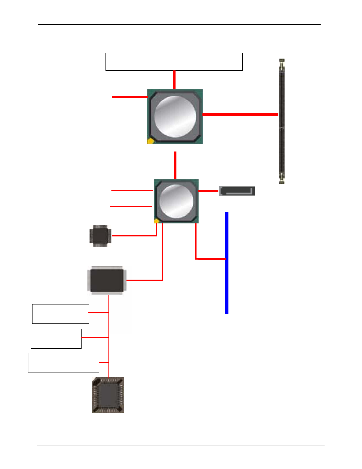
1.4 <Block Diagram>
AMD Geode NX processor
CRT/LCD Monitor
KN400A
Ultra V-Link
1GB/s
1 x 184-pin
DDR266/333/400
Up to 1GB
4 x USB2.0 Port s
2 x SATA
IDE
PCI
AC97 5 .1CH Codec
VT8237R
1 x Serial ports
IrDA
1 x Parallel ports
BIOS
Product Specification 11
2807610 User’s M anual Hardware Setup
Chapter 2 <Hardware Setup>
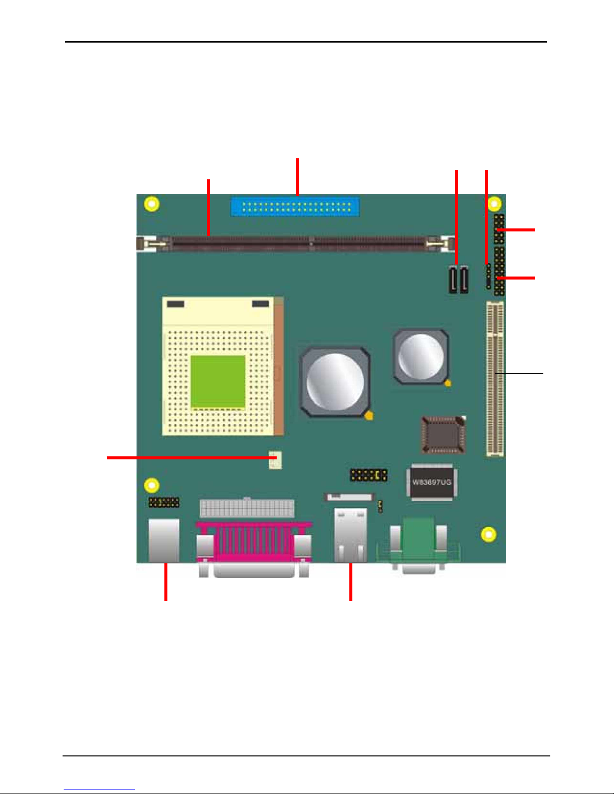
2.1 <Connector Location>
J2
DIMM
J4/J5 J6
J3
J7
J11
J10
J16
J19
J3&17
J21
12 Jumper Reference
2807610 User’ s M anual Introduction
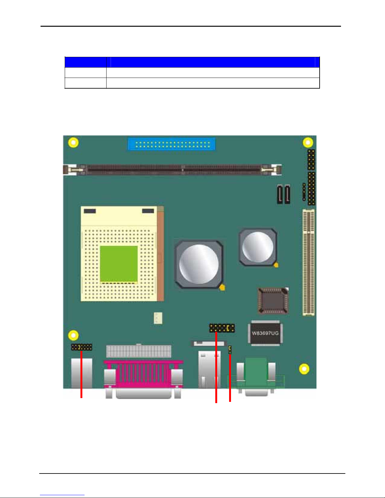
2.2 <Jumper Reference>
Jumper Function
J13 CMOS Operating/Clear Setting.
J14 Setting CPU voltage.
J14 J12 J13
Product Specification 13
 Loading...