

Global American 2801114 User Manual

2801114
User’s Manual
Edition 1.0
Copyright
Copyright© 2002, 2003. All rights reserved. This document is copyrighted and
all rights are reserved. The information in this document is subject to change
without prior notice to make improvements to the products.
This document contains proprietary information and protected by copyright.
No part of this document may be reproduced, copied, or translated in any
form or any means without prior written permission of the manufacturer.
All trademarks and/or registered trademarks contains in this document are
property of their respective owners.
Disclaimer
Global American Inc. shall not be liable for any incidental or consequential
damages resulting from the performance or use of this product.
Global American Inc. does not issue a warranty of any kind, express or
implied, including without limitation implied warranties of merchantability or
fitness for a particular purpose.
The company has the right to revise the manual or include changes in the
specifications of the product described within it at any time without notice and
without obligation to notify any person of such revision or changes.
Trademark
All trademarks are the property of their respective holders.
2801114 User’s Manual
1

Packing List
2801114 :
Hardware
2801114 Motherboard....................................................... X 1
Cable Kit
40-pin ATA100 IDE Flat Cable.......................................... X 1
34-pin Floppy Cable.......................................................... X 1
Dual-USB Port Cable........................................................ X 1
DB9 COM Port Cable........................................................ X 1
Audio Cable ...................................................................... X 1
I/O Shield.......................................................................... X 1
Printed Matter and Software
User’s Manual................................................................... X 1
Driver CD.......................................................................... X 1
2801114 User’s Manual
2

Table of Content
CHAPTER 1. INTRODUCTION........................................................................5
1.1 PRODUCT OVERVIEW ..........................................................................5
1.2 SPECIFICATION ...................................................................................6
1.3 COMPONENT PLACEMENT....................................................................9
1.4 BLOCK DIAGRAM...............................................................................10
CHAPTER 2. HARDWARE SETUP............................................................... 11
2.1 C
ONNECTOR LOCATION ..................................................................... 11
2.2 CPU AND DRAM SETTING................................................................14
2.3 CMOS SETTING...............................................................................15
2.4 WATCHDOG TIMER SETTING...............................................................16
2.5 EMBEDDED SOLID STATE DISK ...........................................................17
2.6 POWER AND FAN CONNECTOR............................................................18
2.7 VGA INTERFACE...............................................................................19
2.8 ETHERNET INTERFACE.......................................................................22
2.9 AUDIO INTERFACE.............................................................................23
2.10 SWITCH AND INDICATOR.....................................................................25
CHAPTER 3. BIOS SETUP............................................................................27
CHAPTER 4 AUDIO CHANNEL CONFIGURATION .....................................29
2801114 User’s Manual
3

APPENDIX. A I/O PORT PIN ASSIGNMENT ................................................ 31
APPENDIX B. FLASH THE BIOS ............................................................... 37
B.1 BIOS A
UTO FLASH TOOL.................................................................. 37
B.2 FLASH METHOD................................................................................ 37
APPENDIX C. SYSTEM RESOURCES......................................................... 39
CONTACT INFORMATION...............................................................................44
2801114 User’s Manual
4

Chapter 1. Introduction
1.1 Product Overview
2801114 is an all-in-o ne industrial compact Pentium 4 level motherboar d
based on Mini-ITX form factor at 170 x 170 mm of dimension. Based on Intel
845GV and ICH4 chipset, 2801114 offers the compact, embedded, value and
high performance solution with Intel Pentium 4 CPU, 533 / 400 MHz of FSB,
1GBytes DDR200/266/333 SDRAM, Intel 845GV GMCH built-in Intel
Extreme Graphics, Intel PRO/100+ LAN, Hi-Speed USB 2.0, IEEE 1394, 5.1
channel and S/P DIF 3D audio, TV-out and embedded flash disk interfaces.
Compact Mini-ITX Form Factor @ 170 x 170 mm
2801114 is based on the ultra compact mini-ITX form factor at only 170 x
170 mm of dimension, meets the demand of compact and powerful
computing platform. With this feature, 2801114 should be the ideal solut ion
for the high-end, Pentium 4 level book-size, slim type and other embedded
PC systems.
Powerful Pentium 4 Computing Platform
With Intel Socket 478 Pentium 4 / Celeron CPU at 533/400 MHz FSB
and 1GBytes DDR200/266/333 SDRAM of system memory, 2801114 offers
the high-end industrial computing platform with low cost Intel integrated
solutions.
Value / High Performance Multi-media Solution
The Intel 845GV GMCH chipset built-in Intel Extreme Graphics, 6
channel and S/P DIF AC97 3D audio make 2801114 be the high
performance but low cost multi-media AV platform. With this feature,
2801114 should be the ideal soluti on for VoD (Video on Demand), DVR
(Digital Video Recorder), digital video broadcasting (DVB), streaming,
surveillance, compression (MPEG), interaction server, POS, Kiosk, ATM,
Panel PC, transaction workstation and terminal applications.
Hi-Speed USB 2.0 and IEEE 1394 Interface
Intel ICH4 built-in Hi-Speed USB 2.0 controller and onb oard IEEE 1394
chipset let 2801114 offer up to 480 Mbps of Hi-Speed USB 2.0 and
100/200/400 Mbps of IEEE 1394 interfaces.
2801114 User’s Manual
5
1.2 Specification
General Specification
Form Factor Mini-ITX at 170 x 170 mm (L x W)
CPU Intel Socket 479 Pentium® 4 Processor - M @ 400 MHz
FSB(no support battery mode)
Memory 1GBytes DDR200/266/333 SDRAM on one 184-pin DIMM
socket
Chipset Intel 82845GV GMCH and 82801DB ICH4
BIOS Phoenix-Award 2Mb PnP flash BIOS
Green Function Power saving mode includes doze, standby and suspend
modes. ACPI version 1.0 and APM version 1.2 compliant
Watchdog Timer System reset programmable watchdog timer with 1 ~ 255
sec./min. of timeout value
Real Time Clock Intel ICH4 built-in RTC with lithium battery
Enhanced IDE PCI enhanced IDE interface supports dual channels and up
to 4 ATAPI devices at UltraATA/100
One 40-pin and one 44-pin IDE port
DiskOnModule (DOM) embedded flash disk up to 1GBytes
Expansive Slot One PCI slot supports up to 2 bus master PCI bus interface
via the additional riser card
Multi-I/O Port
Chipset Intel 82801DB ICH4 (USB) and Winbond W83627HF-AW
LPC Super I/O controller
Serial Port One internal RS-232 serial port with 16C550 compatible
UART and 16 bytes FIFO
USB Port Four Hi-Speed USB 2.0 ports with 480 Mbps of data
transfer rate
Two external and two internal USB ports
Parallel Port One external bi-direction parallel port with SPP/ECP/EPP
mode
Floppy Port One FDD port supports up to two FDD
IrDA Port One IrDA compliant Infrared interface supports CIR/SIR
K/B & Mouse External PS/2 keyboard and mouse ports on rear I/O panel
2801114 User’s Manual
6

VGA Display Interface
Chipset Intel 845GV GMCH built-in Intel Extreme Graphics
With 266 MHz VGA core and 256-bit 3D engine
Memory Intel dynamic video memory up to 64 Mbytes shared with
system
Display Type CRT, LCD monitor and analog display
Up to 4 textures / pixel on a single pass and 2048x2048
texture size
Connector External DB15 female connector on rear I/O panel
Internal 40-pin LVDS connector
TV-out Interface
Chipset Intel 845GV GMCH built-in Intel Extreme Graphics with
Chrontel CH7017A-T TV-out encoder
TV Mode Support both of NTSC and PAL mode
Connector External S-video and RCA Jack on rear I/O panel
Ethernet Interface
Chipset Intel PRO/100+ LAN interface with Intel ICH4 and 82562ET
PHY
Type 10Base-T / 100Base-TX, auto-switching Fast Ethernet
Full duplex, IEEE802.3U compliant
Connector External RJ45 connector with LED on rear I/O panel
Audio Interface
Chipset Intel ICH4 with Realtek ALC650 AC97 3D audio codec
Interface 5.1 channel 3D audio with front (R/L), rear (R/L), center and
bass
S/P DIF digital audio encoding signal input and output
Line-in, line-out, CD-in and MIC-in
Connector External three phone jack for 5.1 channel audio on rear
panel
External S/P DIF connector on rear panel
Internal 10-pin header for line-in/-out, MIC-out, 4-pin header
for CD-in
2801114 User’s Manual
7

IEEE1394 Interface
Chipset Agere FW323 PCI IEEE1394 controller
Interface IEEE1394 with 100/200/400 Mbps of data transfer
bandwidth
Connector External IEEE1394 connector on rear I/O panel
Power and Environment
Power
Requirement
20-pin ATX power connector
Additional +12V on 4-pin connector for Pentium 4 PSU
Dimension 170 (L) x 170 (H) mm, Mini-ITX form factor
Temperature Operating within 0 ~ 60oC (32 ~ 140oF)
Storage within -20 ~ 85
o
C (-4 ~ 185oF)
EMI
Ordering Code
2801114-GAI Mini-ITX Socket 479 Pentium 4 processor –M Motherboard
with Intel Extreme VGA, LAN, TV-out, 5.1-CH/SPDIF Audio,
Hi-Speed USB 2.0, IEEE1394 Interface and LVDS interface.
2801114 User’s Manual
8
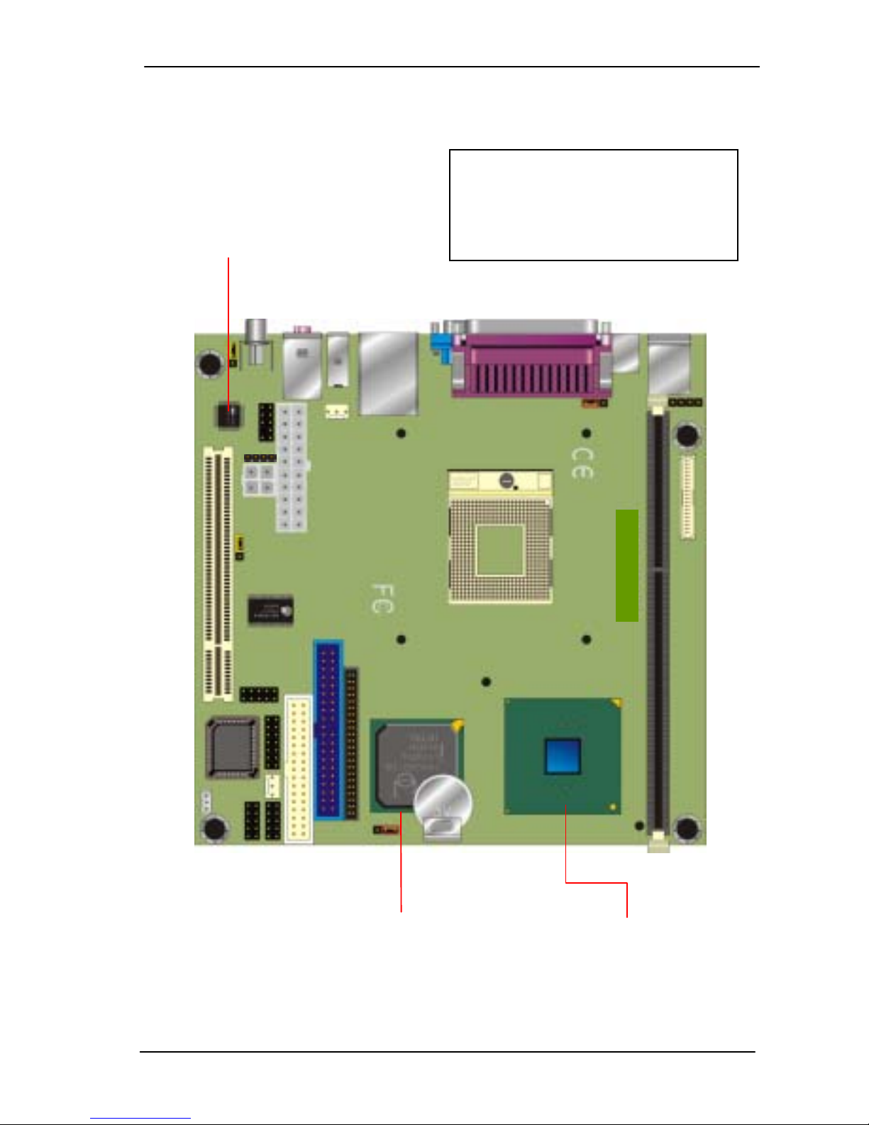
1.3 Component Placement
Intel 845GV GMCH
With 533 / 400 MHz Host Bus
200 / 266 /333 MHz Memory Bus
Intel Extreme Graphics
A
LC650 AC97 Audio Codec
With 5.1 Channel Audio
S/P DIF, Line-in/out, Mic-in
and CD-in Interface
Chipset on Back Side
- Intel 82562ET LAN Phy
- Agere FW323 IEEE1394
Controller
Intel 82801DB ICH4
With Hi-Speed USB 2.0
UltraATA100 IDE
Intel PRO/100+ LAN Mac
2801114 User’s Manual
9
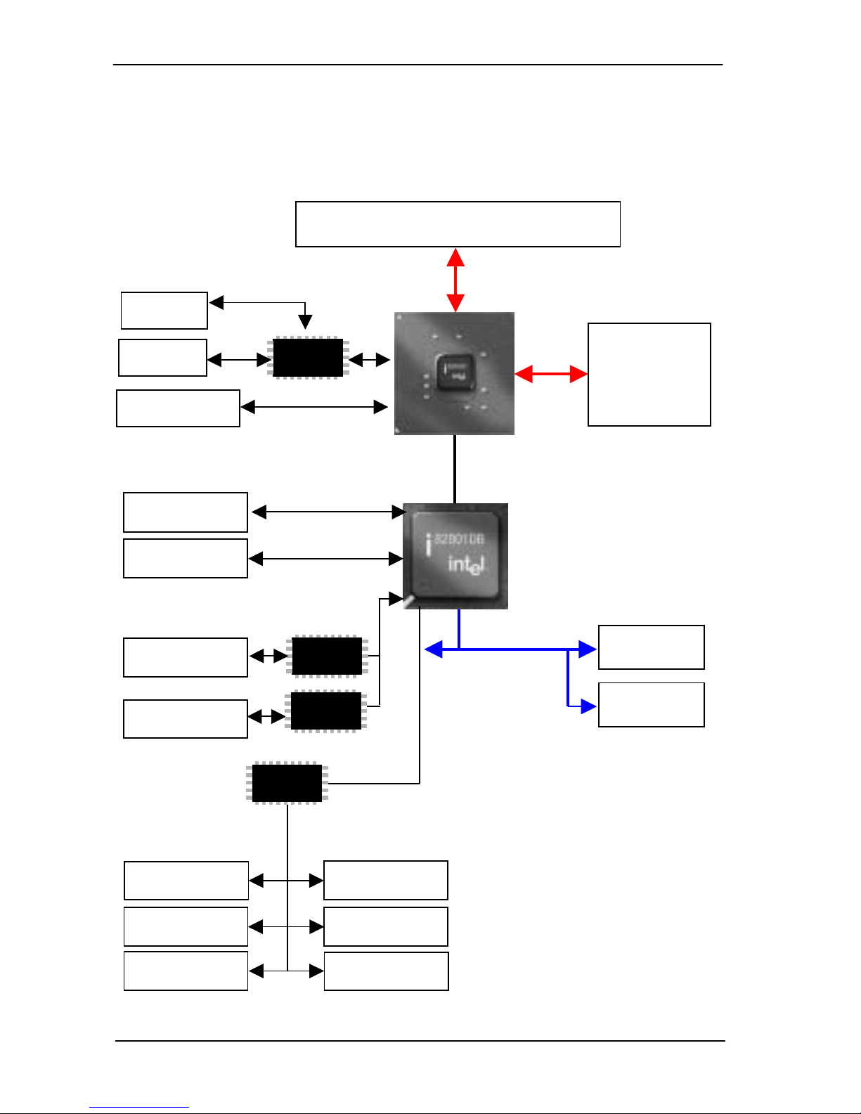
1.4 Block Diagram
One 184-pin
DIMM Sockets
up to 1GBytes
DDR SDRAM
UltraATA100 IDE
100 MBps
FSB 400 / 533 MHz
100 / 133 MHz x 4
DDR200
DDR266
ATAPI Device
LVDS
TV
LVDS
Encoder
LCD
CRT
Intel ICH4
Intel 845G
GMCH
PS/2 Mouse Floppy
Parallel Device
Serial Device
AT Keyboard
LPC
SIO
PS/2 Keyboard
Hi-Speed USB 2.0
480 Mbps
LAN1
Codec
PHY
PCI Bus Interface
PCI Slot
IEEE1394
Audio Devices
USB Devices
Intel Socket 479 Pentium 4 -M
2801114 User’s Manual
10
Chapter 2. Hardware Setup
This chapter contains the information for installation of hardware. The install
procedure includes jumper settings, CPU and memory installation, fan, I/O
and panel connections.
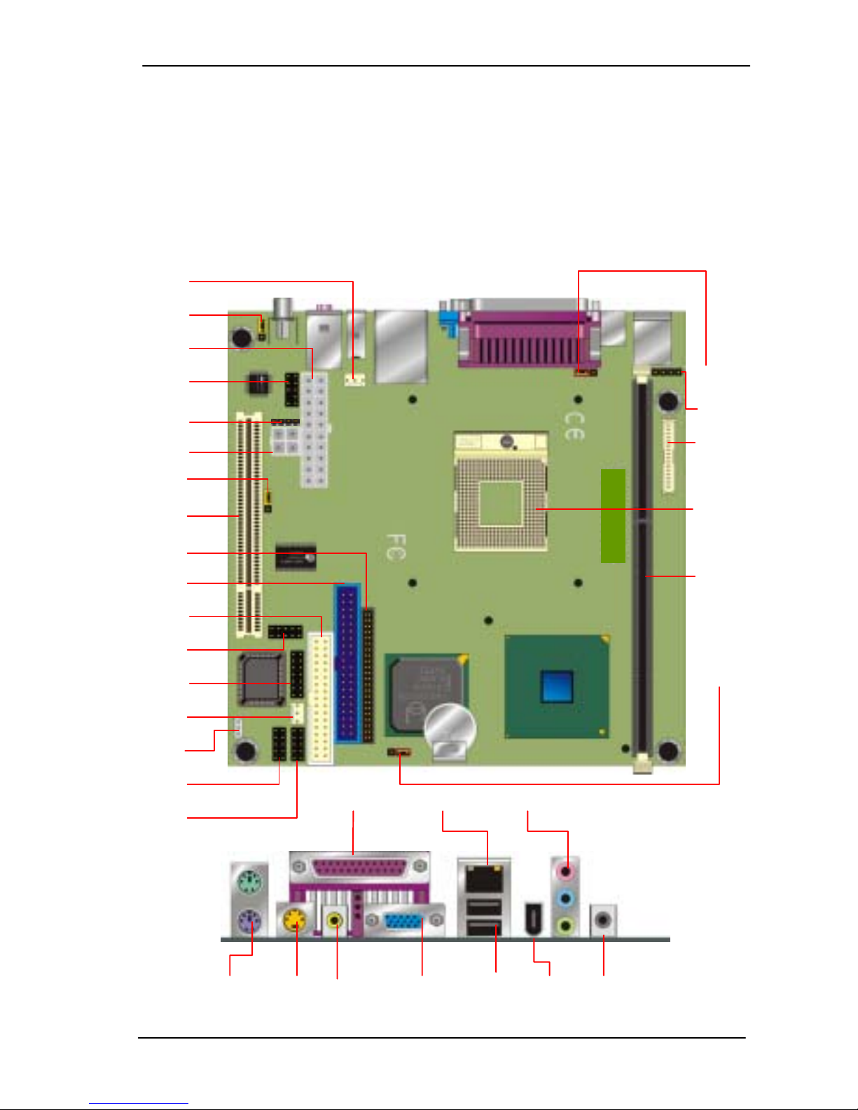
2.1 Connector Location
CPUFAN
J2
PW1
JAUDIO
CDIN1
PW2
J1
PCI1
IDE2
IDE1
FLOPP
Y
JIR1
JFRNT
CHASFAN
JWOL
JCOM1
USB1
J3
J4
CONLCD
CPU
DIMM1
JRTC
PS1 SVDIO1 RJACK1 VGA1 USRJ1 P1 RJACK2
Printer LAN PH1
2801114 User’s Manual
11
2.1.1 Jumper Reference
2801114
Jumper Function
JRTC COMS Operate / Clear Setting
J1 IEEE1394 Enable/Disable Setting
J2 S/P DIF Input / Output Setting
J3 Panel Voltage Setting
Jumper Setting Quick Reference
Jumper 1-2 2-3
JRTC Clean CMOS
Normal Operation
JKBV KB with +5V KB with +5VSB
J1 IEEE1394 Enable IEEE1394 Disable
J2 S/P DIF Output S/P DIF Input
J3 +5V +3.3V
Default setting
2801114 User’s Manual
12

2.1.2 Connector Reference
Internal Onboard Connector
Connector Function Remark
CPU MicroPGA479 CPU Socket Standard
DIMM1 184-pin DIMM Socket Standard
IDE1 40-pin Primary IDE Port Standard
IDE2 44-pin Secondary IDE Port Standard
FDC1 34-pin FDD Port Standard
JCOM1 10-pin COM1 RS-232 Serial Port Standard
USB1 10-pin 3rd / 4th Hi-Speed USB 2.0 Port Standard
JIR1 10-pin CIR / SIR IrDA Port Standard
PW1 20-pin ATX Power Connector Standard
PW2 4-pin Additional +12V Power Connector Standard
JFRNT 14-pin Switch and Indicator Connector Standard
CPUFAN 3-pin +12V CPU Fan Connector Standard
CHASFAN 3-pin +12V System Fan Connector Standard
JAUDIO 10-pin Audio Port Standard
CDIN 4-pin CD-in Interface Standard
WOL1 3-pin Wake-On-LAN Interface Standard
CONLCD 40-pin LVDS connector Standard
J4 5-pin LCD Inverter Power Connector Standard
External Connector on Bracket
Connector Function Remark
PS1 PS2 Keyboard / Mouse 6-pin Connector Standard
Printer Parallel Port DB25 Female Connector Standard
SVDIO1 S-Video TV-out Connector Standard
RJACK1 AV TV-out RCA Jack Standard
VGA1 VGA DB15 Female Connector Standard
LAN LAN RJ45 Connector with LED Standard
USRJ1 Dual USB Connector Standard
P1 IEEE1394 Connector Standard
PH1 Audio RCA Connector Standard
RJACK2 S/P DIF Digital Audio Connector Standard
2801114 User’s Manual
13
2.2 CPU and DRAM Setting
The board is based on Intel Socket 479 architecture with Intel 845G
chipset, supports Intel Socket 479 Pentium 4 Processor –M at 400 MHz
FSB.
System memory of this board supports up to 1GBytes DDR200/266/333
SDRAM on two 184-pin DIMM sockets. Please notices that Intel 845G
GMCH DOESN’T support ECC and register DIMM.
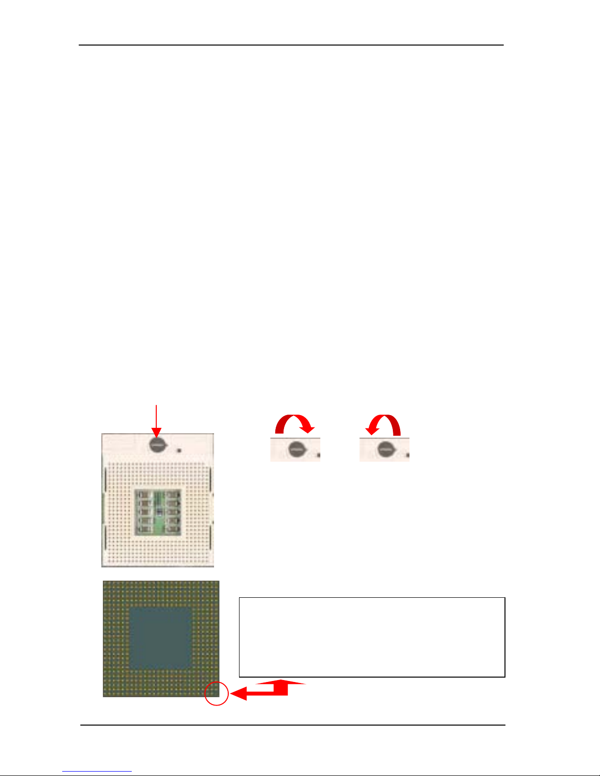
2.2.1 Processor Installation Notice
To install the Intel Pentium 4 Mobile Processor properly,
Please follow the steps blow.
1. Unlock the processor socket.
2. Install the processor onto the socket well.
3. Lock the processor socket.
Lock switch
Unlock Lock
Notice!
Before you install the processor on the socket,
please check the pin director well
2801114 User’s Manual
14
 Loading...