

Global American 2801050 User Manual

User’s Manual
2801050
Mini ITX Board

Copyrights
This manual is copyrighted and all rights are reserved. It does not allow any
non authorization in copied, photocopied, translated or reproduced to any electronic
or machine readable form in whole or in part without prior written consent from
the manufacturer.
In general, the manufacturer will not be liable for any direct, indirect, special,
incidental or consequential damages arising from the use of inability to use the
product or documentation, even if advised of the possibility of such damages. The
manufacturer keeps the rights in the subject to change the contents of this
manual without prior notices in order to improve the function design, performance,
quality and reliability. The author assumes no responsibility for any errors or
omissions, which may appear in this manual, nor does it make a commitment to
update the inf ormation contained herein.
Trademarks
Intel is a registered trademark of Intel Corporation.
Award is a registered trademark of Award Software, Inc.
All other trademarks, products and or product's name mentioned herein are
mentioned for identification purposes only, and may be trademarks and/or
registered trademarks of their respective companies or owners.

ii
CAUTION
Danger of explosion if battery is incorrectly replaced. Replace only with the same or
equivalent type
To be recommended by the manufacturer.
Dispose of used batteries according
To the manufacturer’s instructions
August 2007, Ve
rsion A2

iii
ESD Precautions
Integrated circuits on computer boards are sensitive to static
electricity. To avoid damaging chips from electrostatic
discharge, observe the following precautions:
Do not remove boards or integrated circuits from their anti-static
packaging until you are ready to install them.
Before handling a board or integrated circuit, touch an unpainted
portion of the system unit chassis for a few seconds. This helps to
discharge any static electricity on your body.
Wear a wrist-grounding strap, available from most electronic
component stores, when handling boards and components.
Trademarks Acknowledgments
MS-DOS and Windows ’95 are trademarks of Microsoft
Corporation.
AWARD is a trademark of Award Software. I nc.
IBM, PC/AT, PS/2, VGA are trademarks of Int ernational
Business Machines Corporation.
Intel and Pentium are trademarks of Intel Corporation.
Winbond is a trademark of Winbond Electronics Corp.
SMI is a trademark of Silicon Motion Inc.
Other brand names and trademarks are the properties
and
registered brands of their respective owners.

iv
This page does not contain any information.

Table of Contents v
Table of Contents
Disclaimers............................................................................ii
ESD Precautions..................................................................iii
C h a p t e r 1..............................................................................1
Introduction...............................................................................1
1.1 Specifications .......................................................2
1.2 Utilities Supported................................................4
C h a p t e r 2..............................................................................5
Jumpers and Connectors .........................................................5
2.1 Board Layout and Fixing Holes...........................5
2.2 Placement........................................... .............................7
2.3 Jumper Settings....................................................9
2.3.1 CMOS Clear Jumper: JP1 .............................................10
2.3.2 LVDS Voltage Setting : JP2............................................10
2.3.3 Compact Flash Power: JP3...........................................10
2.3.4 Compact Flash Master/Slave Selection: JP4..............10
2.3.5 COM1 Mode Select: JP11.............................................10
2.3.6 COM2 Mode Select: JP7...............................................11
JP7..........................................................................................11
2.3.7 COM2 Mode Select for RS-232/422/485:JP8/JP5/JP911
2.3.8 COM3 Mode Select: JP10.............................................12
JP10 .........................................................................................12
2.3.9 COM4 Mode Select: JP6...............................................12
JP6 ...........................................................................................12
2.3.10 Keyboard & Mouse Power Selection: JKB1...............12
2.4 Connectors ..........................................................13
2.4.1 ATX Power Connector: CN1.........................................14
2.4.2 Parallel IDE Connector: CN2........................................14
2.4.3 Printer Port Connector: CN3.........................................15
2.4.4 Front Panel Bezel Connector: CN5 ..............................16
2.4.5 CPU FAN1 Connector: CN6..........................................17

vi Table of Contents
2.4.6 USB0~3 Connectors: CN7, CN14(USB).........................17
2.4.7 LVDS Connector: CN8, CN9.................................. ........18
2.4.8 SATA Connector: CN10/CN11......................................19
2.4.9 12V Power Connector: CN12.......................................20
2.4.10 Digital I/O: CN13.........................................................20
2.4.11 LAN Connector: CN14.................................................20
2.4.12 Audio Connector: CN15.............................................21
2.4.13 Compact Flash Connector: CN17.............................21
2.4.14 DDRII DIMM: DDRII 1/ DDRII 2 .....................................22
2.4.15 Serial Port Interface: VCOM1(COM1), COM2-
3(COM2&COM3), CN16(COM4)...........................................22
2.4.16 VGA Connector: VCOM1...........................................23
2.4.17 6-Pin Mini Dim Keyboard/Mouse Connector: KB1 ...24
2.4.18 CPU FAN 2 Connector: FAN1......................................24
2.4.19 System FAN Connector: FAN2....................................25
2.4.20 SPEAK Out Connector: JP12.......................................25
2.4.21 PCI-Express Extension Slot: J1....................................25
C h a p t e r 3............................................................................28
Hardware Description............................................................28
3.1 Microprocessors.................................................28
3.2 BIOS.....................................................................28
3.3 System Memory..................................................28
3.4 I/O Port Address Map .........................................29
3.5 Interrupt Controller.............................................30

Table of Contents vii
4
A p p e n d i x A......................................................................66
Watch Dog Timer....................................................................66
Watchdog Timer Setting ....................................................66
Using the Watchdog Function...........................................67
A p p e n d i x B ......................................................................69
DIO Setting................................... .......................................69
2801050 Pentium® M All-in-One Mini ITX Board User’s Manual
Introduction 1
C h a p t e r 1
Introduction
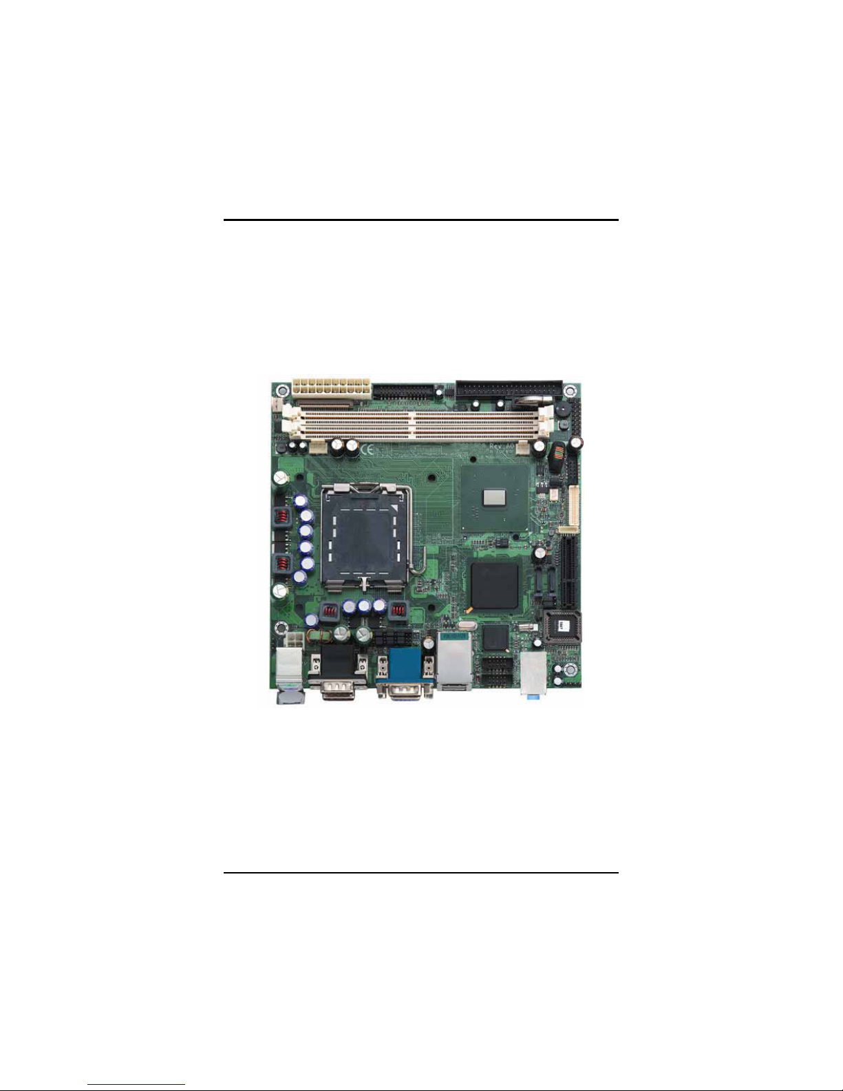
The 2801050 is an Intel
®
LGA775 for Pentium 4 and Celeron
D CPU equipped Mini ITX board with graphics, Fast and Giga
Ethernet and audio interface. Designed with the space-limited
applications in mind, the 2801050 is
practically the finest
embedded
Pentium
4 board that exists. To simplify system

2801050 Pentium® M All-in-One Mini ITX Board User’s Manual
2 Introduction
integration, it packs provisions such as super I/Os, UXGA, LCD,
Ethernet, solid state disk, all on a single board. Unique
embedded features such as 4 serial ports (3 x RS-232,1 xRS232/422/485) Mini ITX bility and that allow adoption of an
extensive array of PC peripherals. The industrial-grade
construction of
2801050 series allow
s your system to endure
the continuou
s operation in hostile environments where
stability and reliability are basic requirements. System
dependability of 2801050 series are
enhanced by its built-in
watc
hdog timer, a special industrial feature not commonly seen
on other motherboards.
Designed for the professional embedded developers, the
Pentium
4 embedded board 2801050 Series is virtually the
ultimate one-step solution for embedded system applications.
1.1 Specifications
z CPU: LGA775 for Pentium 4 and Celeron D
z Chipset: Intel 915GV + ICH*6
z Bus Clock: 533/800MHz
z BIOS:
Phoenix-Award BIOS, Y2K compliant
4Mbit Flash, DMI, Pl ug and Play
SmartView for multiple LCD type selection, display
mode option and application extension features
RPL/PXE Ethernet Boot ROM
“Load Optimized Default” to backup customized
Setting in the BIOS f lash chip to prev ent from CMOS
battery fail
z System Memory:
2*240-pin DDR2 400/533 DIMM max.
Maximum up to 2GB in dual-channel interleaved mode.
z L2 Cache: integrated in CPU
z Onboard IDE:
1 parallel ATA-100 as 1* 44 -pin 2.0 pitch box-header.
2*STA-150 connectors

2801050 Pentium® M All-in-One Mini ITX Board User’s Manual
Introduction 3
z Compact Flash Socket:
One Compact Flash Type II Socket(Optional)
z Onboard Multi I/O:
One floppy port (Optional)
3 x RS-232, 1x RS-232/422/48 5
One LPT port.
z USB Interface: 4 USB ports with fuse protection an d
complies with USB Spec. Rev. 2.0
z Real Time Clock: Integrate Intel
®
ICH*6
z Watchdog Timer:
1~255 seconds; up to 255 levels
z Graphics/Streaming:
Integrate Intel
®
915GV
Unified Memory Architecture shares system memory
up to 128MB
Single display mode maximum resolutions:
CRT: 1600 x1200 @ 60Hz
LVDS LCD: 1600 x 1200
DualView display mode:
CRT: 1600 x1200 @60 Hz
LVDS LCD: 1600 x 1200
LCD backlight control supported
z Ethernet:
One Intel 82562GZ Fast Ethernet
optional Intel 82573E Gigabit
Wake On LAN (via ATX power supply)
Equipped with RJ-45 interface
z Audio:
Realtek AC’97 codec audio
MIC-in, Line-out
z Power Management: ACPI (Advanced Configuration
and Power Interface)

2801050 Pentium® M All-in-One Mini ITX Board User’s Manual
4 Introduction
z Form Factor: Mini ITX form factor
z Size: 170mm* 170mm
NOTE: Specifications are subject to change without notice.
1.2 Utilities Supported
z Chipset Driver
z Ethernet Driver
z VGA Drivers
z Audio Drivers
2801050 Pentium® M All-in-One Mini ITX Board User’s Manual
Jumpers and Connectors 5
C h a p t e r 2
Jumpers and Connectors
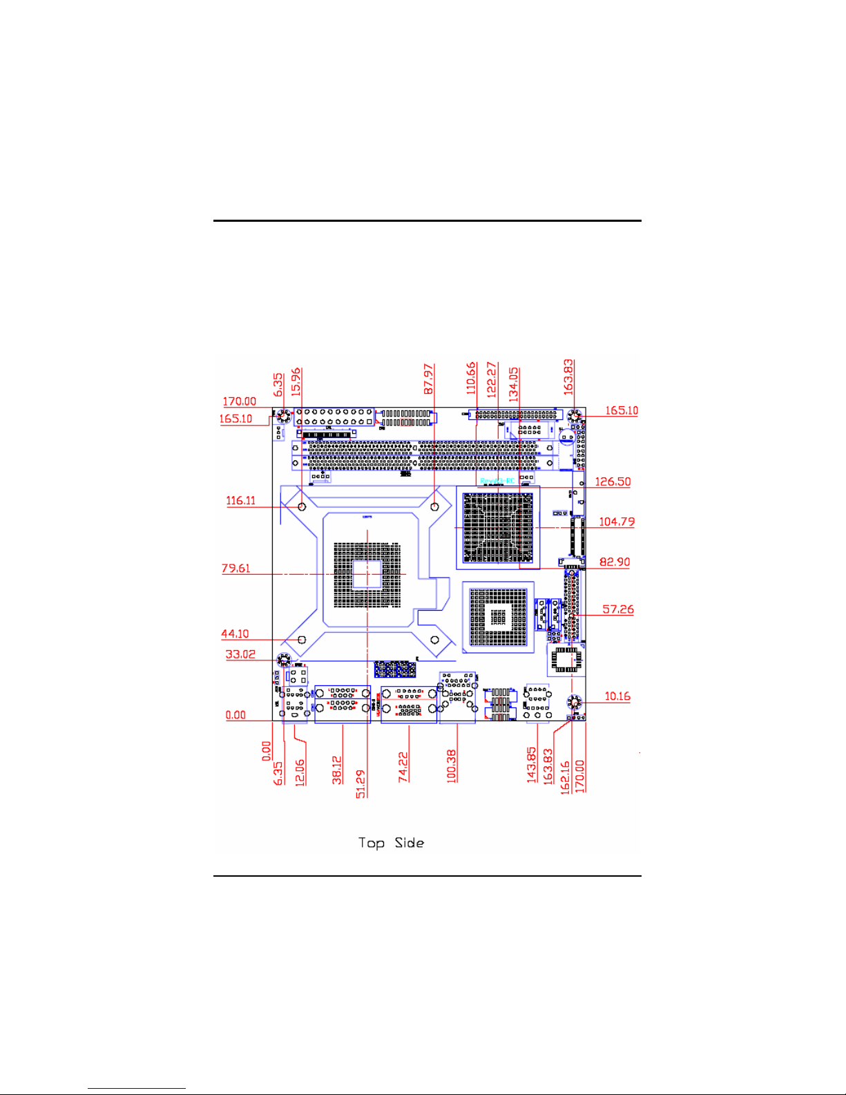
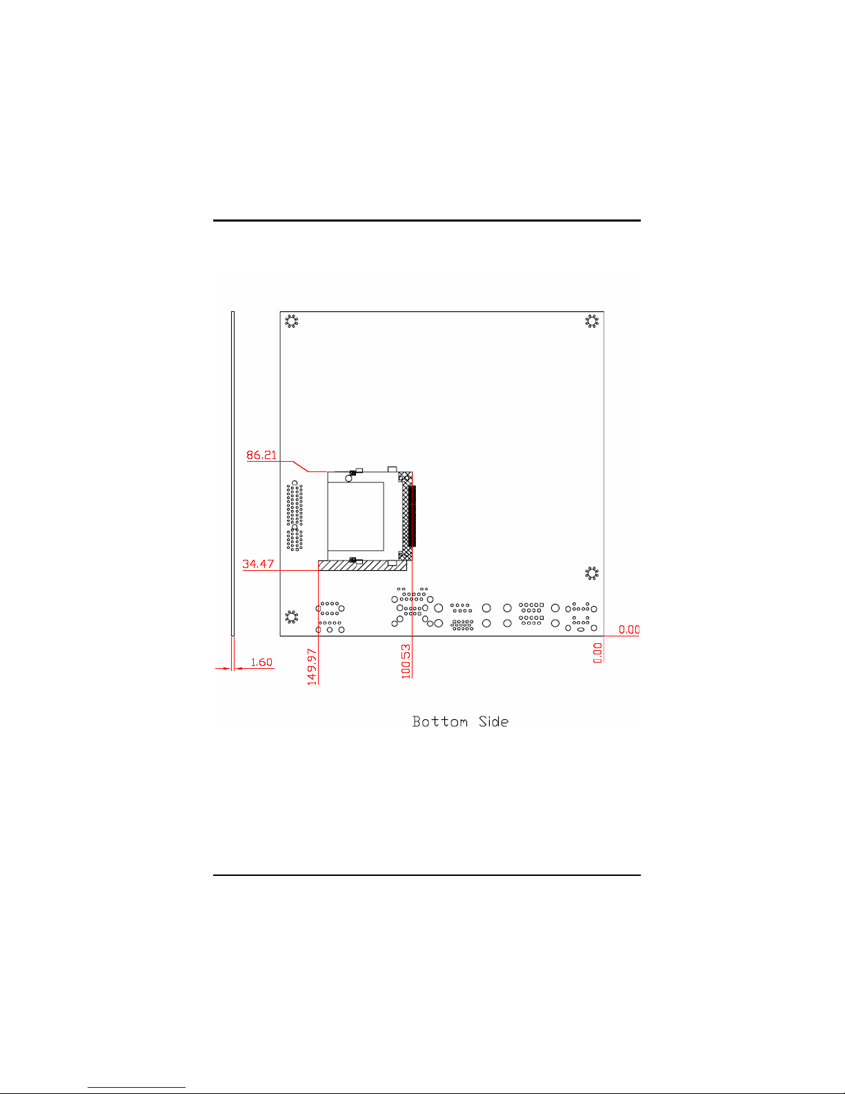
2.1 Board Layout and Fixing Holes
2801050 Pentium® M All-in-One Mini ITX Board User’s Manual
6 Jumpers and Connectors
 Loading...