

Global American 2007598A, 2007598B, 2007600A, 2007600B, 2007602A User Manual
...
GAI-LCD-Series A
2007604, 2007606, 2007608, 2007610.
6.5" to 19" TFT-LCD Monitors
Version 1.11,
User’s Manual for
May 2007
-2007598, 2007600, 2007602,

REVISION HISTORY
Title GAI-LCD Series A Monitor User Manual
Revision
Description Date of Issue
Number
1.0 Initial release November 2006
1.10 - Updated Figure 1-4 and Section 4.4 for DVI/VGA
April 2007
AD Board V2.0
1.11 - DVI/VGA AD Board CN25 connector pin 3 voltage
May 2007
changed to +9V~+36V input
Copyrights
This manual is copyrighted and all rights are reserved. It does not allow any non authorization in
copied, photocopied, translated or reproduced to any electronic or machine readable form in
whole or in part without prior written consent from the manufacturer.
In general, the manufacturer will not be liable for any direct, indirect, special, incidental or
consequential damages arising from the use of inability to use the product or documentation, even
if advised of the possibility of such damages. The manufacturer keeps the rights in the subject to
change the contents of this manual without prior notices in order to improve the function design,
performance, quality and reliability. The author assumes no responsibility for any errors or
omissions, which may appear in this manual, nor does it make a commitment to update the
information contained herein.
Trademarks
Intel is a registered trademark of Intel Corporation.
Award is a registered trademark of Award Software, Inc.
All other trademarks, products and or product's name mentioned herein are mentioned for
identification purposes only, and may be trademarks and/or registered trademarks of their
respective companies or owners.
ABOUT THIS MANUAL
This document covers the description and installation instructions for the GAI-LCD Series A
Monitors. The monitors in this series include the 2007610, 2007608,
2007606, 2007604, 2007602, 2007600 and 2007598.
Page 2
Global American, Inc.

GAI-LCD Series A Monitor
SAFETY PRECAUTIONS
Prior to installing, moving, and modifying the monitor, make sure the power is
turned off and the power cord is disconnected.
Do not apply voltage levels that exceed the specified voltage range. Doing so will
cause fire or an electrical shock.
Electric shocks can occur if the panel is opened. Do not drop or insert any objects
into the ventilation openings of the monitor.
Only qualified engineers from certified system integrators or VARs are allowed to
make necessary functional modifications to the monitor, e.g., adding a touch
panel. GAI offers the customization service on a pre-order basis.
Designs with stand-alone and fault-tolerant hardware consideration s should be
implemented using the series models as a critical alarm or production line control.
If considerable amount of dust, water, or fluids entered the monitor, turn off the
power supply immediately, unplug the power cord, and contact the monitor
vendor.
Explosions may occur with installations in environments where flammable gase s
are present.
Fault-tolerant and failsafe designs should be implemented with the use of the
series models on transportation vehicles, ships, safety/security devices, or
medical devices not related to life-support functionalities. Users/integrators should
take the responsibility for implementations with adequate levels of reliability and
safety.
FURTHER PRECAUTIONS
Do not drop the monitor against a hard surface. Doing so will damage the display.
Do not strike or exert excessive force onto the LCD panel.
Touching the LCD panel using a sharp object will damage the LCD panel.
Avoid environments exposed to direct sunlight, dust, or chemical vapors.
The ambient temperature of the installation site should be observed and
controlled to avoid overheating the monitor.
Page 3

Condensation might form inside the monitor chassis if exposed to sudden
changes in temperature.
Carefully route the power cord so that people cannot step on it. Do not place
anything over the power cord.
If the equipment should be left unused for an extended period of time, disconnect
it from the power source to avoid damage by transient over-voltage.
If any of the following situations arise, have the equipment checked by qualified
service personnel:
o The power cord or plug is damaged.
o Liquid has penetrated into the equipment.
o The equipment has been exposed to moisture.
o The equipment does not work properly, or cannot be made to work
according to the user manual.
o The equipment has been dropped and damaged.
o The equipment shows obvious signs of damage.
WARNING!
Any changes or modifications made to the equipment that are not
expressly approved by the relevant standards could void the authority to
operate the equipment.
ADDITIONAL INFORMA TION AND ASSISTANCE
MAINTENANCE AND CLEANING
Prior to cleaning any part or component of the monitor, please read the details below.
Except for the properly installed front LCD panel, never spray or squirt liquids
directly onto any other component. To clean the LCD panel, please rub it with a
piece of soft dry cloth or a slightly moistened cloth.
The interior of the LCD monitor does not require cleaning. Keep fluids away from
the LCD monitor interior.
Page 4
Global American, Inc.

GAI-LCD Series A Monitor
Be cautious of all small removable components when vacuuming the monitor.
Turn the system off before cleaning the LCD monitor.
Never drop any objects or liquids through the openings of the LCD monitor.
Be cautious of any possible allergic reactions to solvents or chemicals used when
cleaning the monitor.
Avoid eating, drinking and smoking within vicinity of the monitor.
CLEANING TOOLS
Some components in the monitor may only be cleaned using a product specifically
designed for the purpose. In such case, the product will be explicitly mentioned in the
cleaning tips. Below is a list of items to use when cleaning the computer or computer
peripherals.
Cloth – Although paper towels or tissues can be used, a soft, clean piece of cloth
is recommended when cleaning the monitor.
Water or rubbing alcohol – A cloth moistened with water or rubbing alcohol can
be used to clean the monitor.
Using solvents – The use of solvents is not recommended when cleaning the
monitor as they may damage the plastic parts.
Vacuum cleaner – Using a vacuum specifically designed for computers is one of
the best methods of cleaning the monitor. Over dust and dirt can restrict the
airflow in a computer and cause circuitry to corrode.
Cotton swabs - Cotton swaps moistened with rubbing alcohol or water are
excellent tools for wiping hard to reach areas.
Foam swabs - Whenever possible, it is best to use lint free swabs such as foam
swabs for cleaning.
ESD PRECAUTIONS
Observe all conventional anti-ESD methods while handling the components contained
within the LCD should the need arise for adding a function. The use of a grounded wrist
strap and an anti-static work pad is recommended. Avoid dust and debris or other
static-accumulating materials in the work area.
Page 5
CONVENTIONS USED IN THIS MANUAL
WARNING!
Warnings appear where overlooked details may cause damage to the equipment or result
in personal injury. Warnings should be taken seriously. Warnings are easy to recognize.
The word “warning” is written as “WARNING,” both capitalized and bold and is followed by
text in italics. The italicized text is the warning message.
CAUTION!
Cautionary messages should also be heeded to helps reduce the chance of losing data or
damaging the system. Cautions are easy to recognize. The word “caution” is written as
“CAUTION,” both capitalized and bold and is followed by text in italics. The italicized text
is the cautionary message.
NOTE:
These messages inform the reader of essential but non-critical information. These
messages should be read carefully as any directions or instructions contained therein can
helps avoid making mistakes. Notes are easy to recognize. The word “note” is written as
“NOTE,” both capitalized and bold and is followed by text in italics. The italicized text is the
cautionary message.
Lists
Bulleted Lists: Bulleted lists are statements of non-sequential facts that can be read in
any order. Each statement is preceded by a round black dot “•” or bullets in other shapes.
Numbered Lists: Numbered lists describe sequential steps should be followed in order.
Page 6
Global American, Inc.

GAI-LCD Series A Monitor M
Table of Contents
1 INTRODUCTION................................................................................................... 19
1.1 GAI-LCD Series A MONITOR OVERVIEW ............................................................... 20
1.1.1 Standard Features............................................................................................ 20
1.1.2 Model Variations.............................................................................................. 20
1.2 APPLICA TIONS AND FEATURES.................................................................................. 21
1.2.1 GAI-LCD Series A Monitor Applications............................................................ 21
1.2.2 GAI-LCD Series A Monitor Features.................................................................. 21
1.3 EXTERNAL OVERVIEW ............................................................................................. 22
1.3.1 Front View........................................................................................................ 22
1.3.2 Rear View ......................................................................................................... 23
1.3.3 Connectors....................................................................................................... 24
1.3.4 AD Board ......................................................................................................... 25
1.4 SERIES SPECIFICATIONS ........................................................................................... 25
1.5 CERTIFICATIONS....................................................................................................... 27
2 MECHANICAL OVERVIEW............................................................................... 29
2.1 INTRODUCTION ........................................................................................................ 30
2.2 REAR PANEL ............................................................................................................ 30
2.2.1 Rear Panel Variants......................................................................................... 30
2.2.2 Rear Panel Variant 1........................................................................................ 31
2.2.3 Rear Panel Variant 2........................................................................................ 32
2.3 CONNECTOR PANEL.................................................................................................. 32
2.3.1 A vailable Connectors....................................................................................... 32
2.3.2 Variant 1 Connectors ....................................................................................... 33
2.3.3 Variant 2 Connectors ....................................................................................... 33
2.4 PHYSICAL DIMENSIONS............................................................................................ 33
2.4.1 General Physical Dimensions.......................................................................... 33
2.4.2 2007610 Physical Dimensions......................................................................... 34
2.4.3 2007608 Physical Dimensions......................................................................... 35
2.4.4 2007606 Physical Dimensions......................................................................... 36
2.4.5 2007604 Physical Dimensions........................................................................ 37
Page 7

2.4.6 2007602 Physical Dimensions....................................
..................................... 38
2.4.7 2007600 Physical Dimensions......................................................................... 39
2.4.8 2007598 Physical Dimensions......................................................................... 40
2.5 MOUNTING OPTIONS................................................................................................ 41
3 LCD SPECIFICATIONS ....................................................................................... 43
3.1 LCD SPECIFICATIONS .............................................................................................. 44
3.1.1 LCD Overview ................................................................................................. 44
3.1.2 2007610 LCD Specifications........................................................................... 45
3.1.3 2007608 LCD Specifications........................................................................... 46
3.1.4 2007606 LCD Specifications........................................................................... 47
3.1.5 2007604 LCD Specifications........................................................................... 48
3.1.6 2007602B LCD Specifications........................................................................ 49
3.1.7 2007602A LCD Specifications........................................................................ 50
3.1.8 2007600B LCD Specifications........................................................................ 51
3.1.9 2007600A LCD Specifications........................................................................ 52
3.1.10 2007598B LCD Specifications...................................................................... 53
3.1.11 2007598A LCD Specifications ...................................................................... 54
3.2 P
OWER ADAPTERS ................................................................................................... 55
4 AD BOARDS........................................................................................................... 57
4.1 AD BOARD OVERVIEW ............................................................................................ 58
4.2 VGA640 AD BOARD .............................................................................................. 58
4.2.1 VGA640 AD Board Overview .......................................................................... 58
4.2.2 VGA640 AD Board Connectors ....................................................................... 58
4.2.3 VGA640 AD Board Layout............................................................................... 59
4.2.4 VGA640 Peripheral Interface Connectors....................................................... 59
4.2.5 VGA640 Rear Panel Connectors ..................................................................... 60
4.2.6 VGA640 Onboard Jumper................................................................................ 60
4.2.7 VGA640 Internal Peripheral Connectors........................................................ 61
4.2.8 5V Power Connector........................................................................................ 61
4.2.9 Debugged Port Connector............................................................................... 62
4.2.10 External OSD and LED Indication Connector.............................................. 63
4.2.11 Serial Communications Connector ................................................................ 64
4.2.12 TTL Output Connector................................................................................... 65
4.2.13 VGA Connector.............................................................................................. 67
Page 8
Global American, Inc.

GAI-LCD Series A Monitor
4.2.14 VGA640 External (Rear Panel) Connectors.................................................. 68
4.2.15 DC 12V Connector.........................................................................................
68
4.2.16 RS232 Serial Connector................................................................................. 69
4.2.17 OSD Control Buttons..................................................................................... 70
4.2.18 VGA Connector.............................................................................................. 71
4.2.19 VGA640 Onboard Jumper.............................................................................. 72
4.2.20 LCD Panel (TTL) Voltage Select Jumper....................................................... 73
4.3 VGA800 AD BOARD ............................................................................................... 74
4.3.1 VGA800 AD Board Overview .......................................................................... 74
4.3.2 VGA800 AD Board Connectors ....................................................................... 74
4.3.3 VGA800 AD Board Layout............................................................................... 75
4.3.4 VGA800 Peripheral Interface Connectors....................................................... 76
4.3.5 VGA800 Rear Panel Connectors ..................................................................... 76
4.3.6 VGA800 Onboard Jumper................................................................................ 76
4.3.7 VGA800 Internal Peripheral Connectors........................................................ 77
4.3.8 5V Power Connector........................................................................................ 77
4.3.9 Backlight Inverter Connector .......................................................................... 78
4.3.10 External OSD and LED Indication Connector.............................................. 79
4.3.11 LVDS Output Connector ................................................................................ 80
4.3.12 VGA Connector.............................................................................................. 81
4.3.13 VGA800 External (Rear Panel) Connectors.................................................. 83
4.3.14 DC 12V Connector......................................................................................... 83
4.3.15 VGA Connector.............................................................................................. 84
4.3.16 VGA800 Onboard Jumper.............................................................................. 85
4.3.17 LCD Panel Voltage Select Jumper................................................................. 86
4.4 DVI/VGA AD BOARD OVERVIEW .......................................................................... 87
4.4.1 DVI/VGA AD Board Connectors .................................................................... 88
4.4.2 DVI/VGA AD Board Layout............................................................................ 89
4.4.3 DVI/VGA Peripheral Interface Connectors.................................................... 90
4.4.4 DVI/VGA Rear Panel Connectors .................................................................. 90
4.4.5 DVI/VGA On-board Jumpers.......................................................................... 91
4.4.6 DVI/VGA Internal Peripheral Connectors..................................................... 91
4.4.7 Auto-Dimming Connector................................................................................ 91
4.4.8 Debug Port Connector..................................................................................... 92
4.4.9 External OSD and LED Indication Connector................................................ 93
4.4.10 Backlight Inverter Connector ........................................................................ 94
Page 9

4.4.11 LVDS Output Connector
................................................................................ 95
4.4.12 Power Output Connector............................................................................... 96
4.4.13 Power Input Connector.................................................................................. 97
4.4.14 VGA Connector.............................................................................................. 99
4.4.15 DVI/VGA On-board Jumpers......................................................................... 100
4.4.16 LCD Panel Power Input Jumper.................................................................. 101
4.4.17 LCD Panel Voltage Select Jumper............................................................... 101
4.4.18 DVI/VGA External (Rear Panel) Connectors................................................ 102
4.4.19 DC 12V Connector....................................................................................... 102
4.4.20 VGA Connector............................................................................................ 103
4.4.21 DVI-D Connector......................................................................................... 104
5 INSTALLATION .................................................................................................. 105
5.1 I
NSTALLATION PRECAUTIONS................................................................................. 106
5.2 UNPACKING............................................................................................................ 107
5.2.1 Packaging ...................................................................................................... 107
5.2.2 Unpacking Procedure .................................................................................... 107
5.2.3 Packing List ................................................................................................... 108
5.3 PRE-INSTALLATION PREPARATION .......................................................................... 108
5.3.1 Tools............................................................................................................... 108
5.4 CONNECTORS......................................................................................................... 109
5.4.1 VGA Connector.............................................................................................. 109
5.4.2 DVI-D Connector........................................................................................... 109
5.4.3 12V Power Connector.....................................................................................110
OUNTING THE GAI-LCD Series A MONITOR.......................................................110
5.5 M
6 ON-SCREEN-DISPLAY (OSD) CONTROLS ....................................................111
6.1 USER MODE OSD STRUCTURE ...............................................................................112
6.1.1 OSD Buttons....................................................................................................112
6.1.2 OSD Menu Structure – All Models Except 2007598.......................................113
6.1.3 2007598A OSD Menu Structure.....................................................................115
6.2 USING THE OSD......................................................................................................116
6.2.1 Main Display Features....................................................................................116
6.2.2 Color...............................................................................................................117
6.2.3 Language.........................................................................................................118
6.2.4 OSD Configurations........................................................................................118
Page 10
Global American, Inc.

GAI-LCD Series A Monitor
6.2.5 Signal ............................................................................................................. 120
6.2.6 Backlight........................................................................................................ 120
A CERTIFICATIONS.............................................................................................. 123
OHS COMPLIANT................................................................................................ 124
A.1 R
Page 11

List of Figures
Figure 1-1: Typical GAI-LCD Series A Front View....................................................22
Figure 1-2: Typical GAI-LCD Series A Rear View.....................................................23
Figure 1-3: Typical GAI-LCD Series A Connectors..................................................24
Figure 1-4: DVI/VGA AD Board...................................................................................25
Figure 2-1: Rear Panel Variant 1................................................................................31
Figure 2-2: Rear Panel Variant 2................................................................................32
Figure 2-3: 2007610 Physical Dimensions (millimeters).........................................34
Figure 2-4: 2007608 Physical Dimensions (millimeters).........................................35
Figure 2-5: 2007606 Physical Dimensions (millimeters).........................................36
Figure 2-6: 2007604 Physical Dimensions (millimeters).........................................37
Figure 2-7: 2007602A Physical Dimensions (millimeters)......................................38
Figure 2-8: 2007600A Physical Dimensions (millimeters)......................................39
Figure 2-9: 2007598A Physical Dimensions (millimeters)......................................40
Figure 4-1: VGA640 AD Board Overview..................................................................58
Figure 4-2: Connector and Jumper Locations.........................................................59
Figure 4-3: 5V Power Connector Location ...............................................................61
Figure 4-4: Debugged Port Connector Location......................................................62
Figure 4-5: External OSD and LED Indication Connector Location.......................63
Figure 4-6: Serial Communications Connector Location........................................64
Figure 4-7: TTL Output Connector Location ............................................................66
Figure 4-8: VGA Connector Location........................................................................67
Figure 4-9: VGA640 External (Rear Panel) Connectors..........................................68
Figure 4-10: RS232 Serial Connector Pinout Locations..........................................69
Figure 4-11: VGA Connector Pinout Locations........................................................71
Figure 4-12: Jumpers..................................................................................................72
Figure 4-13: Jumper Location....................................................................................72
Page 12
Global American, Inc.

GAI-LCD Series A Monitor
Figure 4-14: VGA800 AD Board Overview................................................................74
Figure 4-15: Connector and Jumper Locations .......................................................75
Figure 4-16: 5V Power Connector Location .............................................................77
Figure 4-17: Backlight Inverter Connector Location...............................................78
Figure 4-18: External OSD and LED Indication Connector Location.....................79
Figure 4-19: LVDS Output Connector Location .......................................................81
Figure 4-20: VGA Connector Location......................................................................82
Figure 4-21: VGA800 External (Rear Panel) Connectors........................................83
Figure 4-22: VGA Connector Pinout Locations........................................................84
Figure 4-23: Jumpers..................................................................................................85
Figure 4-24: Jumper Location....................................................................................85
Figure 4-25: DVI/VGA AD Board Overview................................................................87
Figure 4-26: Connector and Jumper Locations .......................................................89
Figure 4-27: Auto-dimming Connector Location.....................................................92
Figure 4-28: Debug Port Connector Location ..........................................................93
Figure 4-29: External OSD and LED Indication Connector Location.....................94
Figure 4-30: Backlight Inverter Connector Location...............................................95
Figure 4-31: LVDS Output Connector Location .......................................................96
Figure 4-32: Power Output Connector Locations....................................................97
Figure 4-33: Power Input Connector Locations.......................................................98
Figure 4-34: VGA Connector Location......................................................................99
Figure 4-35: Jumpers............................................................................................... 100
Figure 4-36: Jumper Locations............................................................................... 100
Figure 4-37: DVI/VGA External (Rear Panel) Connectors..................................... 102
Figure 4-38: VGA Connector Pinout Locations..................................................... 103
Figure 4-39: DVI-D Connector Pinout Locations................................................... 104
Figure 5-1: VGA Connector..................................................................................... 109
Figure 5-2: DVI-D Connector................................................................................... 110
Figure 5-3: 12V Power Connector........................................................................... 110
Figure 6-1: OSD Control Buttons for All Models Except 2007598A .................... 112
Page 13

Figure 6-2: 2007598A OSD Control Buttons......................................................... 113
Figure 6-3: Main Display Features.......................................................................... 116
Figure 6-4: Color Options........................................................................................ 117
Figure 6-5: Language Menu .................................................................................... 118
Figure 6-6: OSD Configurations Menu................................................................... 119
Figure 6-7: Signal Menu........................................................................................... 120
Figure 6-8: Backlight Menu ..................................................................................... 120
Page 14
Global American, Inc.

GAI-LCD Series A Monitor
List of Tables
Table 1-1: GAI-LCD Series A Specifications.............................................................26
Table 2-1: Rear Panel Variants...................................................................................30
Table 2-2: General Physical Dimensions..................................................................33
Table 2-3: Mounting Holes .........................................................................................41
Table 3-1: 2007610 LCD Specifications....................................................................45
Table 3-2: 2007608 LCD Specifications....................................................................46
Table 3-3: 2007606 LCD Specifications....................................................................47
Table 3-4: 2007604 LCD Specifications....................................................................48
Table 3-5: 2007602B LCD Specifications..................................................................49
Table 3-6: 2007602A LCD Specifications.................................................................50
Table 3-7: 2007600B LCD Specifications..................................................................51
Table 3-8: 2007600A LCD Specifications .................................................................52
Table 3-9: 2007598B LCD Specifications..................................................................53
Table 3-10: 2007598A LCD Specifications ...............................................................54
Table 3-11: Power Adapter Specifications ...............................................................55
Table 4-1: VGA640 Peripheral Interface Connectors ..............................................60
Table 4-2: VGA640 Rear Panel Connectors .............................................................60
Table 4-3: VGA640 Onboard Jumper........................................................................60
Table 4-4: 5V Power Connector Pinouts...................................................................61
Table 4-5: Debugged Port Connector Pinouts.........................................................62
Table 4-6: External OSD and LED Indication Connector Pinouts..........................63
Table 4-7: Serial Communications Connector Pinouts...........................................64
Table 4-8: TTL Output Connector Pinouts................................................................65
Table 4-9: VGA Connector Pinouts ...........................................................................67
Table 4-10: DC 12V Connector Pinouts.....................................................................68
Table 4-11: RS232 Serial Connector Pinouts...........................................................69
Page 15

Table 4-12: OSD Control Button JP1 Pinouts ..........................................................70
Table 4-13: OSD Control Button JP2 Pinouts ..........................................................70
Table 4-14: OSD Control Button JP3 Pinouts ..........................................................70
Table 4-15: OSD Control Button JP4 Pinouts ..........................................................70
Table 4-16: VGA Connector Pinouts .........................................................................71
Table 4-17: LCD Panel (TTL) Voltage Select Jumper Settings ...............................73
Table 4-18: VGA800 Peripheral Interface Connectors ............................................76
Table 4-19: VGA800 Rear Panel Connectors ...........................................................76
Table 4-20: VGA800 Onboard Jumper......................................................................76
Table 4-21: 5V Power Connector Pinouts.................................................................77
Table 4-22: Backlight Inverter Connector Pinouts...................................................78
Table 4-23: External OSD and LED Indication Connector Pinouts........................79
Table 4-24: LVDS Output Connector Pinouts...........................................................80
Table 4-25: VGA Connector Pinouts .........................................................................82
Table 4-26: DC 12V Connector Pinouts.....................................................................83
Table 4-27: VGA Connector Pinouts .........................................................................84
Table 4-28: LCD Panel Voltage Select Jumper Settings .........................................86
Table 4-29: DVI/VGA Peripheral Interface Connectors ............................................90
Table 4-30: DVI/VGA Rear Panel Connectors ...........................................................90
Table 4-31: DVI/VGA On-board Jumpers...................................................................91
Table 4-32: Auto-dimming Connector Pinouts.........................................................91
Table 4-33: Debug Port Connector Pinouts..............................................................92
Table 4-34: External OSD and LED Indication Connector Pinouts........................93
Table 4-35: Backlight Inverter Connector Pinouts...................................................94
Table 4-36: LVDS Output Connector Pinouts...........................................................96
Table 4-37: Power Output Connector Pinouts (CN12).............................................97
Table 4-38: Power Output Connector Pinouts (CN13).............................................97
Table 4-39: Power Input Connector Pinouts (CN24)................................................98
Table 4-40: Power Input Connector Pinouts (CN25)................................................98
Table 4-41: VGA Connector Pinouts .........................................................................99
Page 16
Global American, Inc.

GAI-LCD Series A Monitor
Table 4-42: LCD Panel Power Input Jumper Settings .......................................... 101
Table 4-43: LCD Panel Voltage Select Jumper Settings ...................................... 101
Table 4-44: DC 12V Connector Pinouts.................................................................. 102
Table 4-45: VGA Connector Pinouts ...................................................................... 103
Table 4-46: DVI-D Connector Pinouts .................................................................... 104
Table 5-1: Rear Panel Connectors.......................................................................... 109
Table 5-2: VGA Connector Pinouts ........................................................................ 109
Table 5-3: DVI-D Connector Pinouts ...................................................................... 110
Table 6-1: OSD Menus – All Models Except 2007598A......................................... 114
Table 6-2: 2007598A OSD Menus............................................................................ 116
Page 17

THIS PAGE IS INTENTIONALLY LEFT BLANK
Page 18
Global American, Inc.

GAI-LCD Series A Monitor
Chapter
1
Introduction
Page 19

1.1 GAI-LCD Series A Monitor Overview
The GAI-LCD Series A monitor is the latest member of GAI’s line of sophisticated LCD
designs, and it has been improved to be RoHS compliant. It is designed to fit industrial
automation, or any other applications that require minimum installation space and
flexible configuration. Flexible analog or digital interfaces are provided for ease of
connection with a management computer. If remote/non-attentive control is preferred,
RS-232 or USB interfaces can be used with customized adapter cables.
1.1.1 Standard Features
All the base models listed in Section 1.2.1 have the following standard features
LCD monitor
OSD controls
VGA
Robust metal chassis
RoHS compliant
1.1.2 Model Variations
The GAI-LCD Series A offers the following model variations.
2007598A: 6.5” LCD screen
2007598B: 6.5” LCD screen + high luminance
2007600A: 8.4” LCD screen
2007600B: 8.4” LCD screen + high luminance
2007602A: 10.4” LCD screen
2007602B: 10.4” LCD screen + high luminance
2007604: 12.1” LCD screen
2007606: 15” LCD screen
2007608: 17” LCD screen
2007610: 19” LCD screen
Page 20
Global American, Inc.

1.2 Applications and Features
1.2.1 GAI-LCD Series A Monitor Applications
GAI’s series of LCD monitors are designed for system manufacturers, integrators, or
value-added resellers that want to provide all the performance, quality and reliability of an
LCD display solution at a cost effective price. GAI’s LCD series offer additional components
such as cables, an inverter and power supply with controller interfaces that include VGA
and DVI.
1.2.2 GAI-LCD Series A Monitor Features
Some of the features of the GAI-LCD series A monitor include:
GAI-LCD Series A Monitor
Analog VGA interface supports most general system boards
Over 300 cd/m2 high brightness and 50,000 hrs MTFB long lifetime panel
Advanced thermal and air-flow design
Supports panel mounting
12V DC power input via adapter
Long product life support
RoHS compliant
Page 21
1.3 External Overview
The following sections describe the physical layout of the GAI-LCD series A monitors.
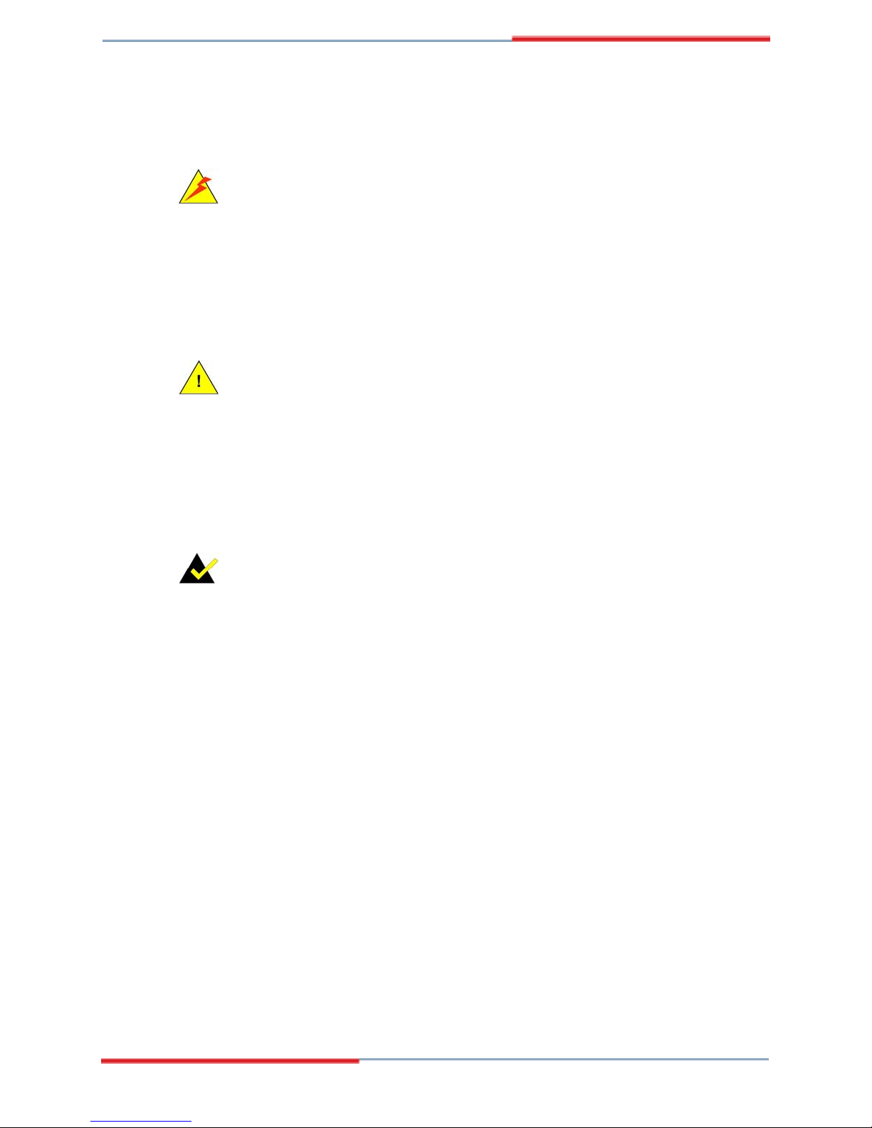
1.3.1 Front View
The front of the GAI-LCD series A monitor is a flat panel TFT LCD screen attached to a
metal chassis. Figure 1-1 shows a typical GAI-LCD Series A front view.
Figure 1-1: Typical GAI-LCD Series A Front View
Page 22
Global American, Inc.
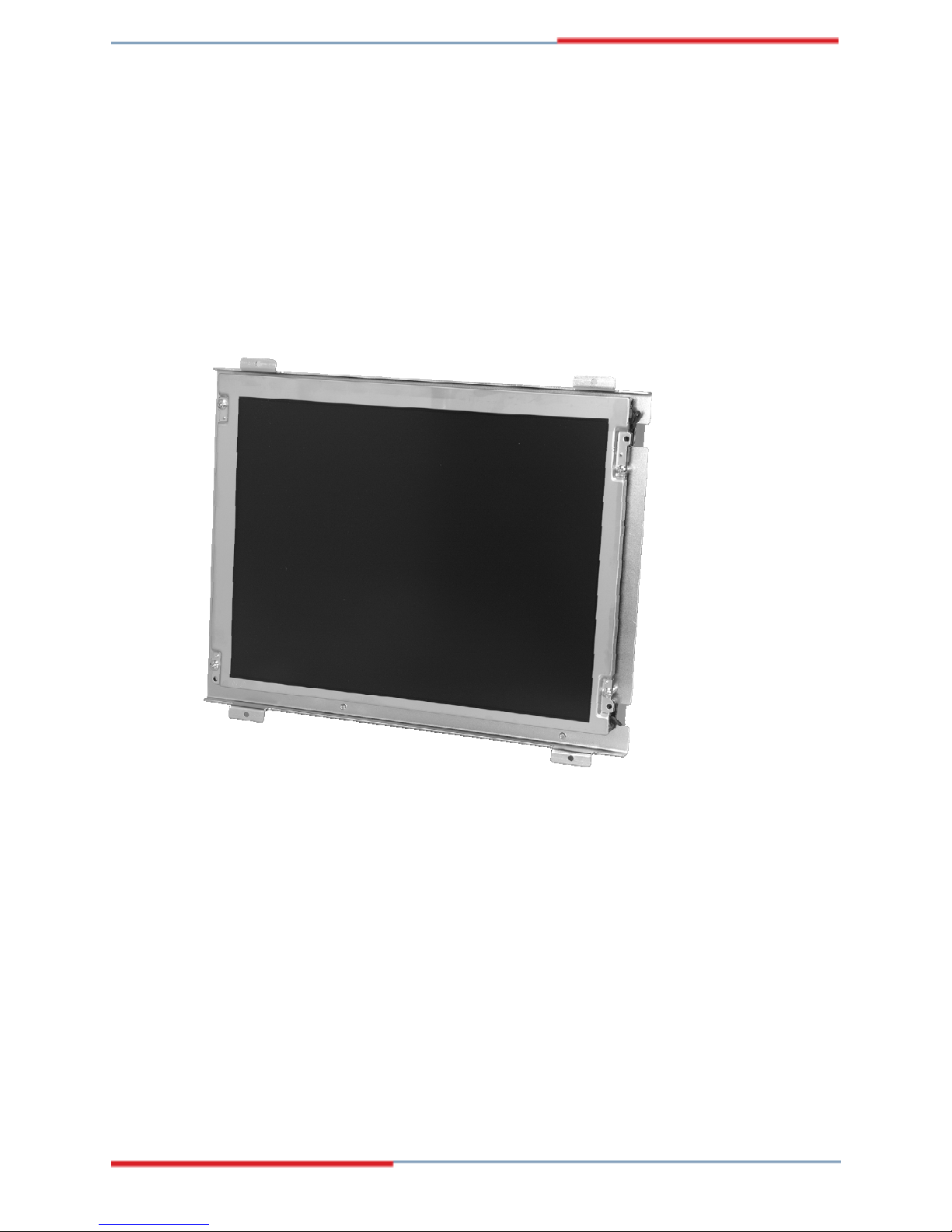
1.3.2 Rear View
The rear of the GAI-LCD series A monitor is a metal chassis. An on screen display (OSD)
control button panel, if present, is located vertically on the left side of the chassis with the
following control buttons:
The OSD panel also has one power LED.
GAI-LCD Series A Monitor
LCD On/Off
Auto
Left
Right
Menu
Figure 1-2 shows a typical GAI-LCD Series A rear panel.
Figure 1-2: Typical GAI-LCD Series A Rear View
Page 23
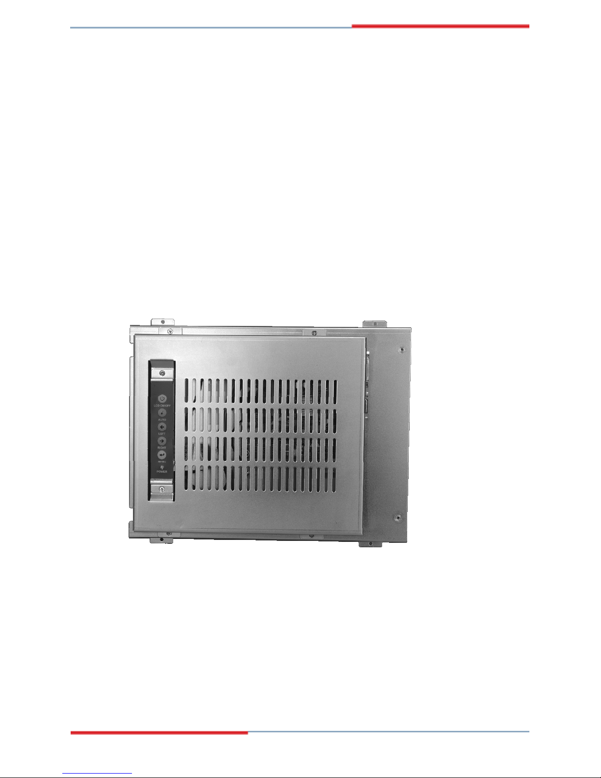
1.3.3 Connectors
Each GAI-LCD Series A monitor has a number of interface connectors on either the top or
right panel of the chassis (when viewing the rear panel). Figure 1-3 shows a typical
GAI-LCD Series A connector panel. Each model may include or exclude additional connectors.
Refer to Section 2.3 for listings of GAI-LCD Series A's and their conn
descri
bed in Section 5.4.
Figure 1-3: Typical GAI-LCD Series A Connectors
ectors. All connectors are fully
Page 24
Global American, Inc.
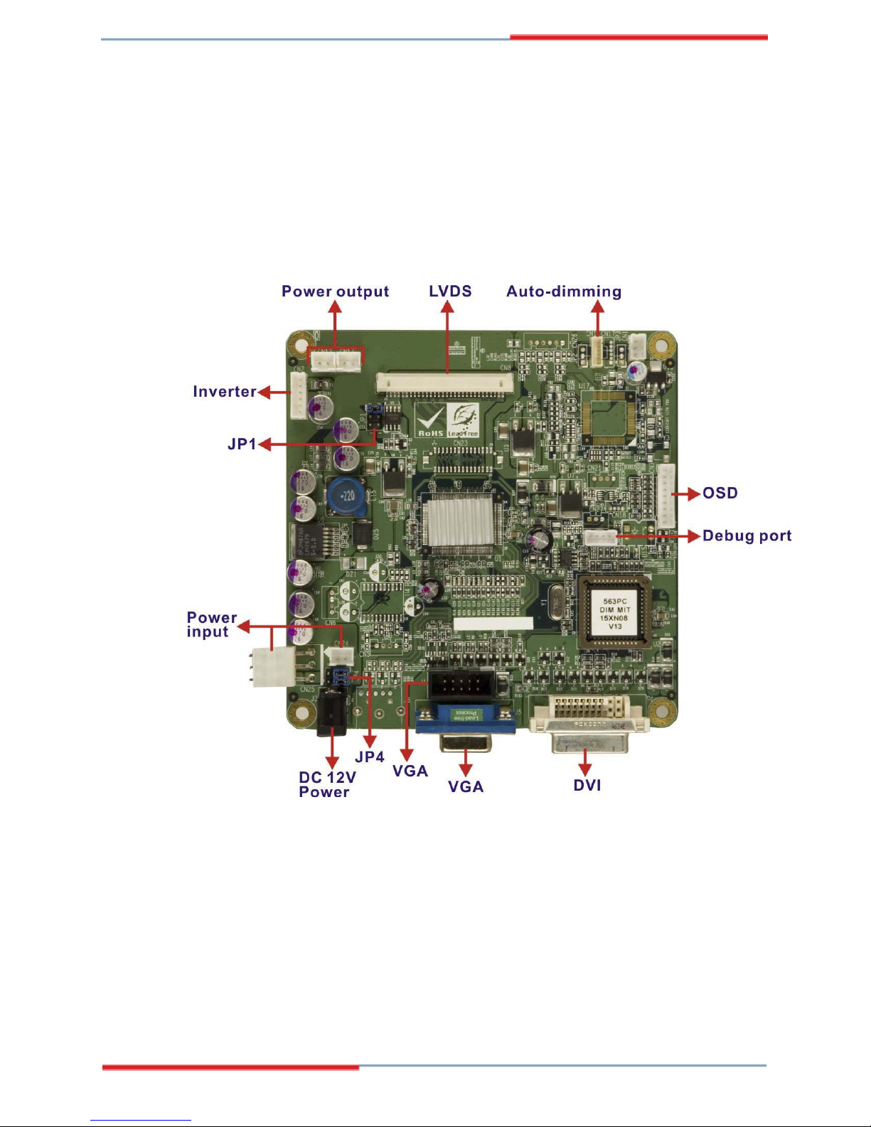
1.3.4 AD Board
The GAI-LCD Series A monitor AD boards provide a wide variety of control interfaces,
receiving and managing signals from a CPU card through cabling. Figure 1-4 shows the
GAI-LCD Series A Monitor
DVI/VGA AD board as a sample of a typical AD board for the GAI-LCD Series A monitor.
Refer to Chapter 4 for a complete description of AD boards and their co
nnectors.
Figure 1-4: DVI/VGA AD Board
1.4 Series Specifications
Table 1-1 shows the GAI-LCD Series A specifications.
Page 25
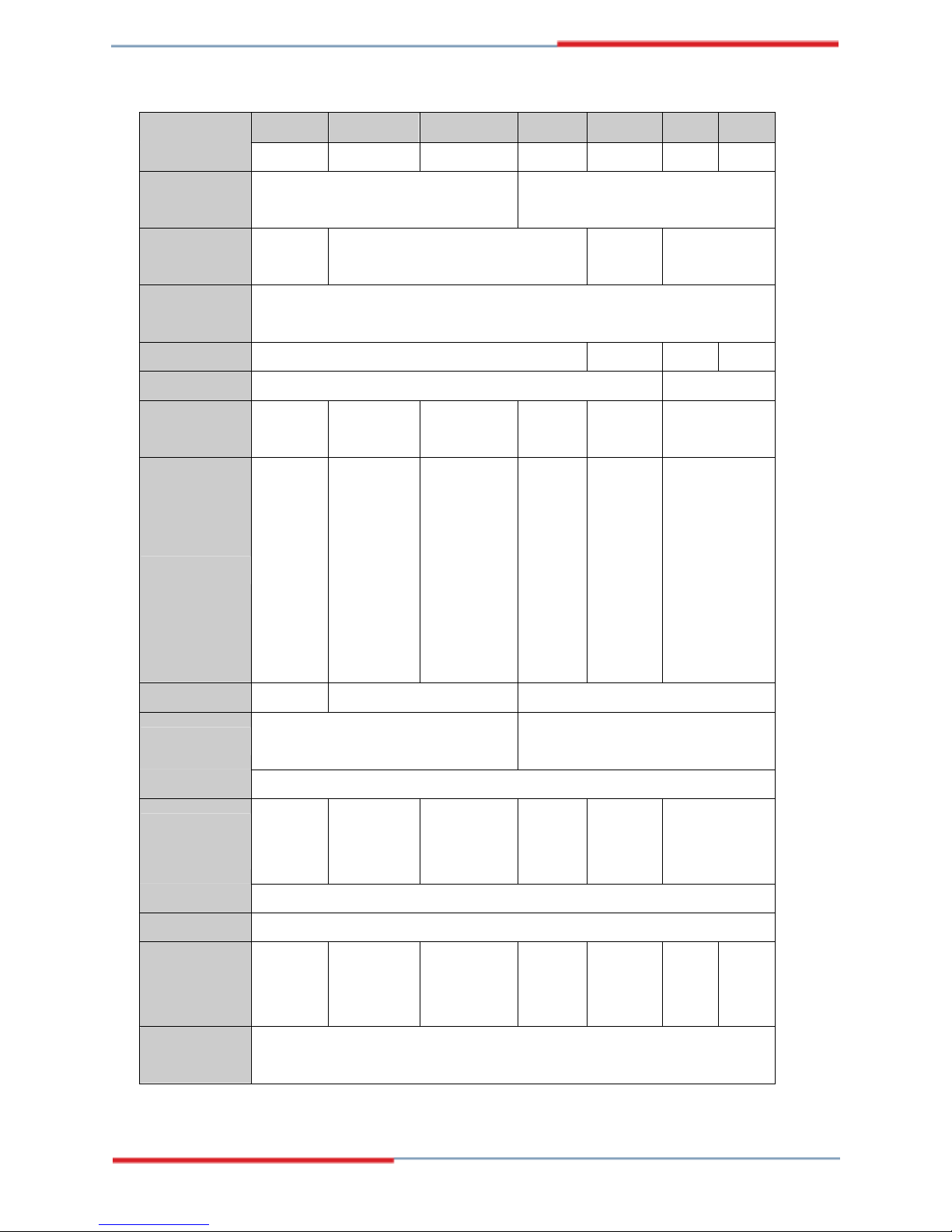
GAI-LCD
2007598A
LCD Type 6.5" TFT 8.4" TFT 10.4" TFT 12.1" TFT 15" TFT 17" TFT 19" TFT
2007600A
2007602A
2007604 2007606
2007608
2007610
Input
VGA VGA + DVI-D
Interface
Max.
640x480 800x600 1024x768 1280x1024
Resolution
Backlight
50,000 Hrs
MTBF
Contrast 500:1 400:1 500:1 700:1
LCD Color 262K 16.2M
Brightness
400/500 220/450 230/400 400 350 300
(cd/m2)
7F700-
PLCD0312101
AG-RS
or
7F700-
2
)
2
)
(230 cd/m
PLCD02102G-RS
(400 cd/m
7F700-
QF82V4-
RS
7F700-
QF117V116-
RS
7F700-
PLCD2817418-
RS
Inverter
7F700-
LV12ETG-RS
(400 cd/m
LV12EAG-RS
(500 cd/m
2
or
7F700-
2
7F700-
LV1401TG-RS
(220 cd/m
)
or
7F700-
LCD19062C-RS
(450 cd/m
)
2
)
2
)
AD Board VGA640 VGA800 VGA-DVI
25W
45W
Power Adapter
63000-UP0251E12PL02-RS
63000-UP0451E12P81L-RS
Chassis Heavy-duty steel
130/110
View Angle
140/120
or
120/100 140/110 120/100 140/130
(H / V)
120/100
OSD function Yes
Mounting Panel
Dimension
(WxHxD)
(mm)
203 x
121 x
34
234 x
147 x
35.3
242.2 x
209 x
33.6
294 x
240.7 x
42
364.1 x
262.5 x
41.9
390.4 x
300 x
46.9
Operation
0~50°C
Temperature
Table 1-1: GAI-LCD Series A Specifications
427.9 x
327.4 x
48.4
Page 26
Global American, Inc.

1.5 Certifications
All GAI-LCD Series A monitor models comply with the following international standards:
RoHS
For a more detailed description of these standards, please refer to Appendix A.
GAI-LCD Series A Monitor
Page 27

THIS PAGE IS INTENTIONALLY LEFT BLANK
Page 28
Global American, Inc.

GAI-LCD Series A Monitor
Chapter
2
Mechanical Overview
Page 29
2.1 Introduction
This chapter describes the general mechanical overview of the GAI-LCD Series A monitors
including rear panel variations, available interfaces and overall dimensions.
2.2 Rear Panel
The rear panel of the GAI-LCD Series A monitor is comprised of a metal chassis with an OSD
control panel.
2.2.1 Rear Panel Variants
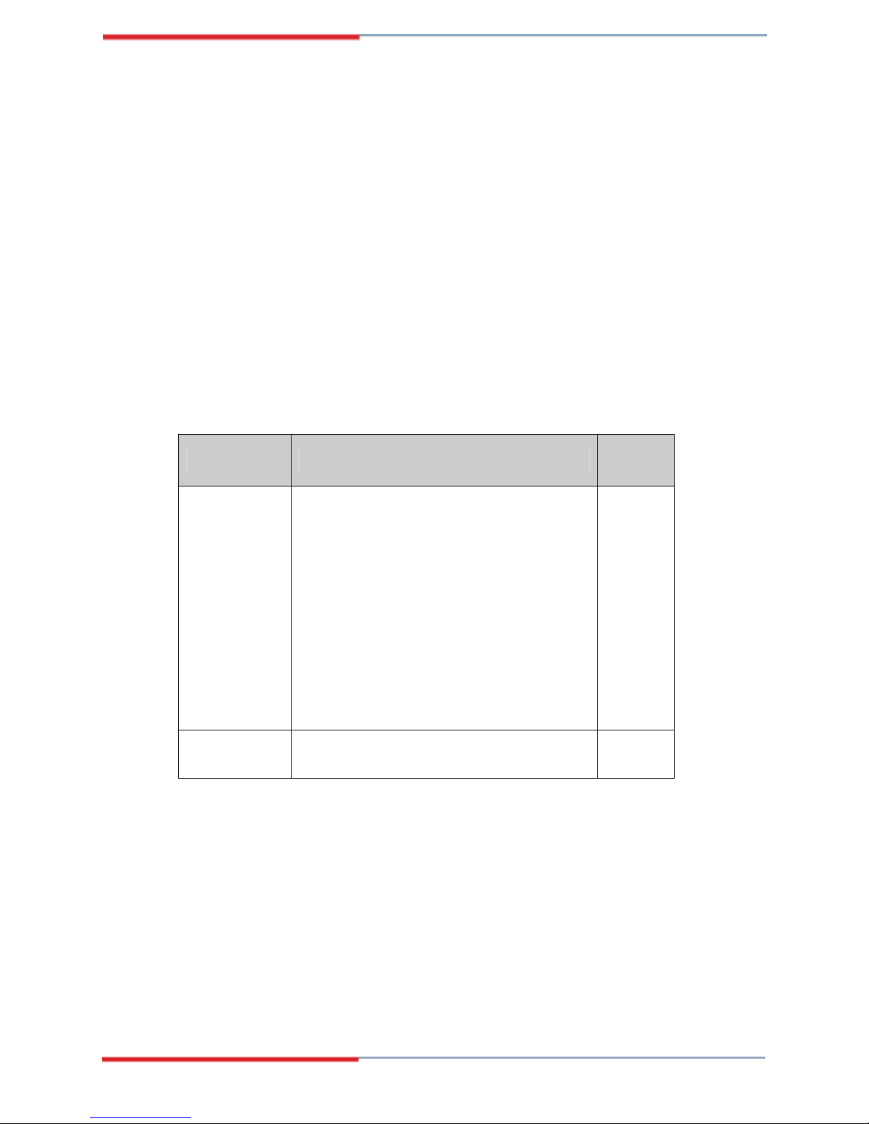
Table 2-1 shows the rear panel variants for the GAI-LCD Series A monitor.
Model OSD Control Panel Location
2007610
2007608
2007606
Vertically along the left side of the rear panel. 1
2007604
2007602
2007600
2007598 In line along the bottom of the rear panel. 2
Table 2-1: Rear Panel Variants
Variant
Number
Page 30
Global American, Inc.
 Loading...