

Global American 1404150 Quick Installation Manual

Quick Installation Guide
1404150
Version 1.0

Copyrights
This manual is copyrighted and all rights are reserved. It does not allow any non authorization in
copied, photocopied, translated or reproduced to any electronic or machine readable form in whole or in
part without prior written consent from the manufacturer.
In general, the manufacturer will not be liable for any direct, indirect, special, incidental or
consequential damages arising fr om the use of inability to use the product or documentation, even if
advised of the possibility of such damages. The manufacturer keeps the rights in the subject to change
the contents of t his manual without prior notices in order to improve the function design, performance,
quality and reliability. The author assumes no responsibility for any errors or omissions, which may
appear in this ma nual, nor does it make a commitment to update the information contained herein.
Trademarks
Intel is a registered tr ademark of Intel Corporation.
Award is a registered trademark of Award Software, Inc.
All other trademarks, products and or product's name mentioned herein are mentioned for
identification purposes only, and may be trademarks and/or registered trademarks of their
respective companies or owners.
1404150 QIG Page 2
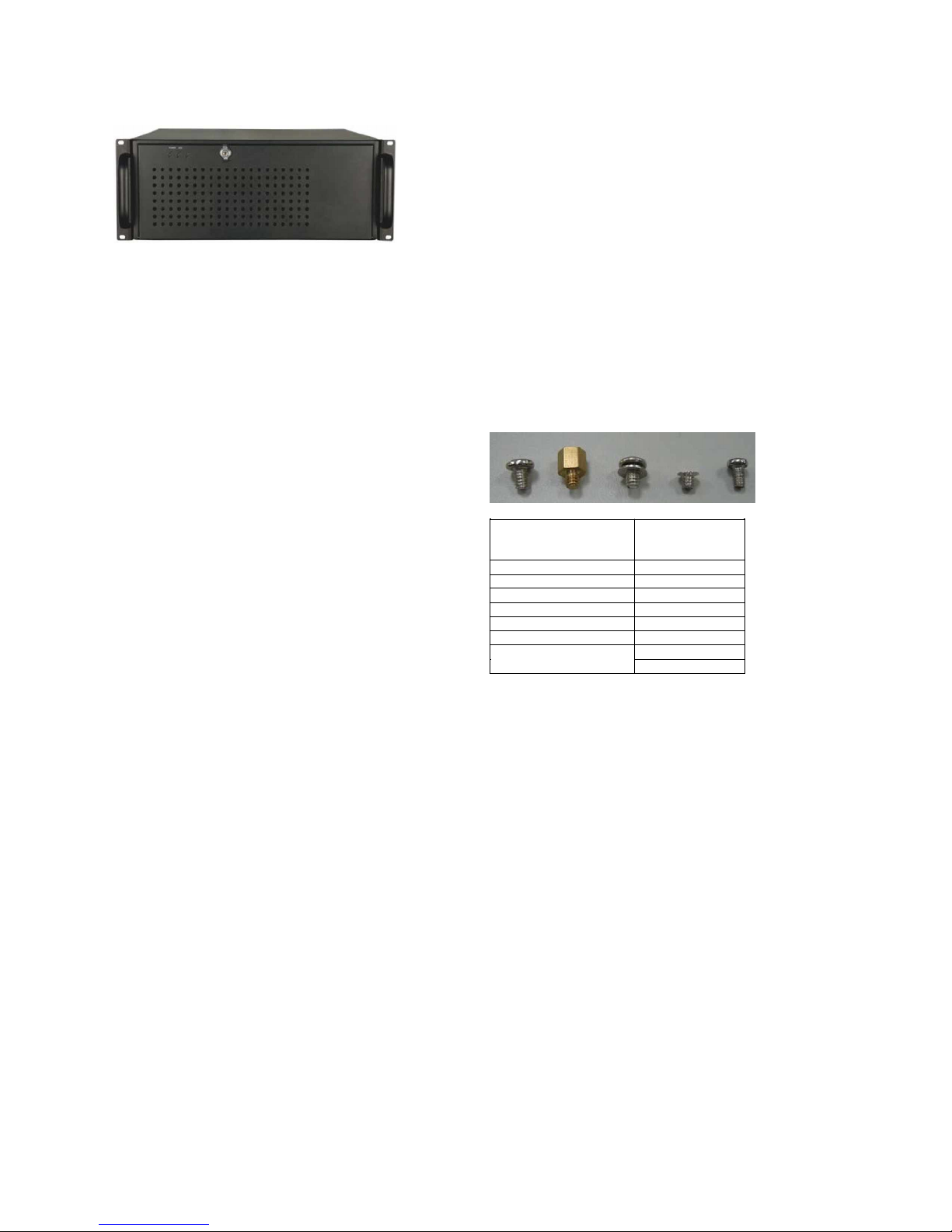
ABOUT THE 1404150
The 4U, heavy-duty steel 1404150 AT/ATX compatible
rackmount industrial chassis is designed to oper ate reliably in
industrial environments where it wi ll be exposed to dust, wide
temperature variations, and shocks and vibrations, among other
things.
SPECIFICATIONS
„
Form Factor:
„
SBC Form Factor:
„
Construction:
„
Slot Number:
o 14 slots for 1404150
o 7 slots for 1404150ATX
„
Cooling:
„
Drive Bay Combina tions:
o 3 x 5.25” Optical drive bays
o 3 x 3.5” FDD (floppy disk drive) or HDD (h ard disk
„
Dimensions (DxWxH)
520 mm x 431mm x 176mm
„
Operating Temperature
„
Relative Humidity
„
Vibra tion:
5-17Hz, 0.1” double amplit ude displacement
17-640Hz, 1.5G acceleration peak to peak
„
Shock:
Standard 4U, 19” wide
Full-size, slot CPU cards
Metal
2 x 8cm fans
drive) bay
:
: 0~40° C
: 10~90%
10G acceleration peak to peak
PACKING LI ST
When you unpack the chassis, make sure the following items
have been shipped.
„ 1 x Quick Installat ion Gu ide
„ 1 x Power cord
„ 2 x Handles
„ 1 x Screw set
„ 3 x Shock absorbers
„ 5 x Shock absorbers
„ 2 x Plastic pillars
„ 1 x Cab le tie
„ 1 x backplane-to-CPU card A TX cable
„ 2 x Keys
DETAILS OF INCLUDED SCREWS
The attached screw set includes five screw t ypes. Screws
used for chassis installati on are shown below.
1 2 3 4 5
Peripherals/Parts
5.25” Optical Drives 5
3.5” FDD 5
3.5” HDD 1
2.5” HDD 4
Power Supply Unit 1
Rackmount Bracket 3
Backplane 3
Table 1: Screws for Peripheral/Parts
Screw Label (refer
to the picture
above)
2
1404150 QIG Page 3
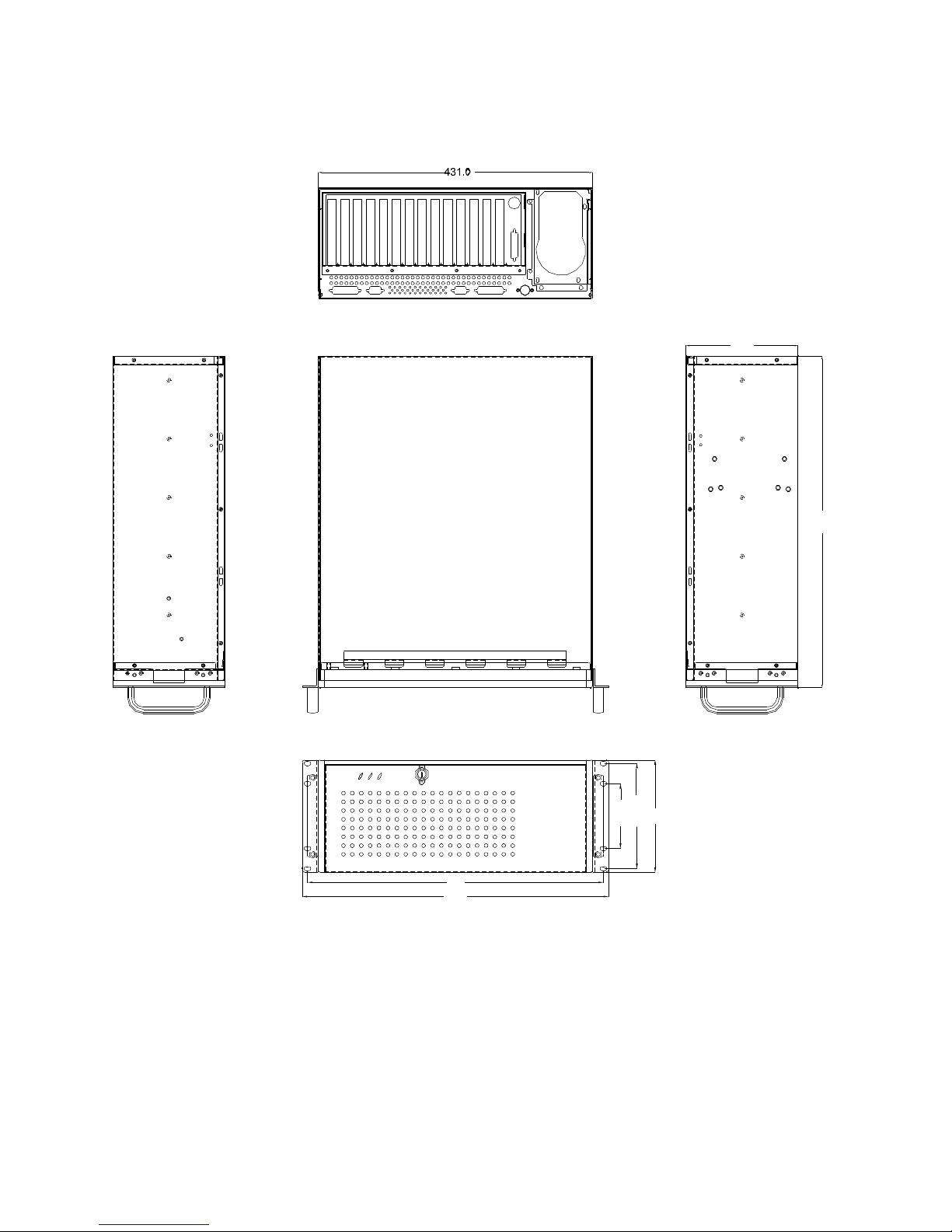
DIMENSIO N DR AWING
The dimensions of 140 4150 are show n in the figure below.
176
POWER
HDD
465
481.8
Figure 1: Dimension Drawing (measurement units: millimeter)
1404150 QIG Page 4
INSTALLATION STEPS
To install the 1404150 chassis, the following installation steps must
be completed.
Step 1:
Step 2:
Step 3:
Step 4:
Step 5:
Step 6:
Step 7:
Step 8:
Step 9:
Unpack the chassis.
Remove the top cover and hold-down clamp.
Install the PSU.
Install the backplane.
Install the CPU card.
Install the PCI and ISA expansion cards.
Install the internal HDD.
Install the disk drives.
Connect the cables.
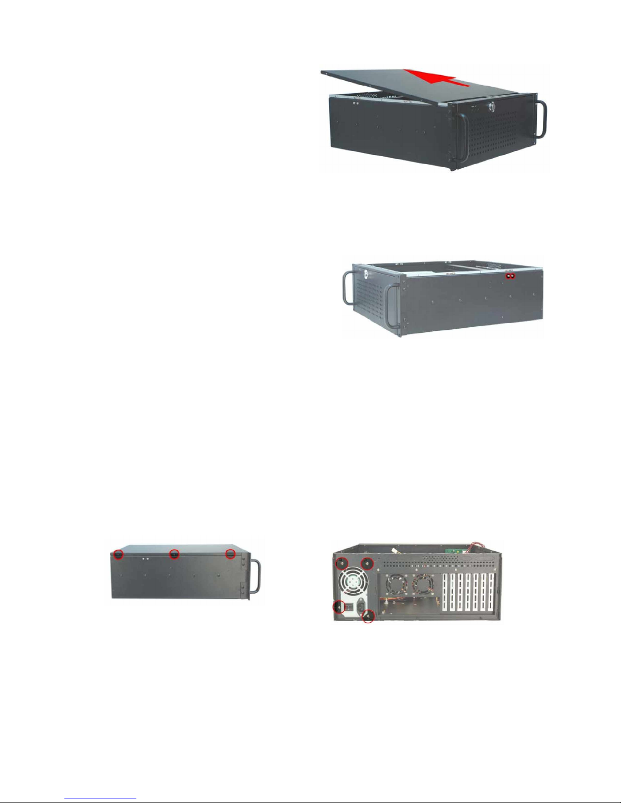
Figure 3: Remove the Top Cover
S
TEP
2.2: H
Detach the hold-down clamp by removing the two retention
screws located on each side of the chas sis and lift t he
hold-down clamp off the chassis.
OLD-DOWN CLA MP R EMO VA L
Step 10:
Step 11:
Step 12:
The installation steps outlined above are described in detail below.
Please refer to the relevant section.
Connect PSU cable and interface cable.
Install the front handles.
Reinstall the hold-down clamp a nd the top cover.
Step 0:
STEP 1: UNPACK
The 1404150 is shipped in a plastic bag that is placed inside a
cardboard box. When the chassis is unpacked, make sure
„ All the items listed in the
present.
„ The chassis has not been damaged in anyway .
PACKING LI ST
section are
STEP 2: TOP COVER AND HOLD-DOWN
CLAMP R EMOVAL
S
TEP
2.1: R
EMOVE THETOPCOVER
The top cover is secure d by si x retention scr ews on both side s, thr ee
on each side, of the chassis. To remove the top cover, follow th e
steps below:
Step 1:
Remove all six top cover retention screws. Remove three
retention screws from each side of the chassis.
Figure 4: Hold-Down Clamp Retention Screws
STEP 3: INSTALL THE POWER SUPPLY
UNIT (PSU)
Once th e top cover and hold-down clamp h ave been re moved,
the PSU must be installed. Compatible Global American, Inc
PSUs are listed in
The PSU is installed at the rear of the chassis and secured to the
chassis with six retention screws. To install the PSU, please
follow the steps below.
Step 1:
Step 2:
table 2
on
page 4
.
Mount the PSU at the rear of the chassis. Make sur e the
power socket and the PSU fan face outwards.
To secure the PSU to the chassis, insert six retention
screws, four rear retention screws and two internal
retention screws.
Step 0:
Figure 2: Top Cover Retention Screws
Step 2:
Slide the cover backwards and then lift the cover up
gently .
Step 0:
1404150 QIG Page 5
Figure 5: PSU Retention Screws at the Rear
 Loading...