

Global Air NPA1 Use And Care Manual
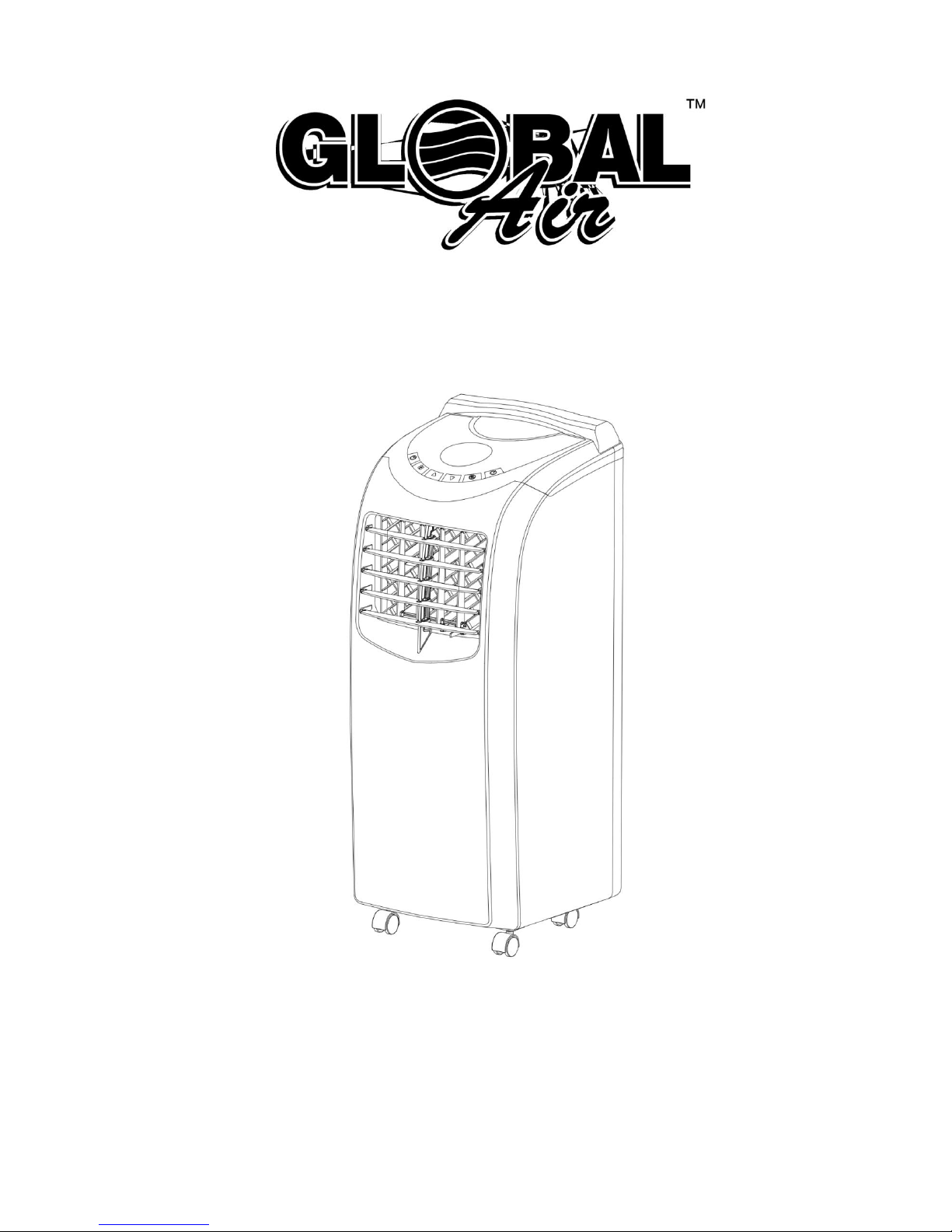
Portable Air-conditioner
Use and Care Manual
Model: NPA1
Thank you very much for selecting this new model of Portable Air Conditioner, please read this Use and Care Manual
carefully before installing and using this appliance. Please keep this Use and Care Manual properly for future
reference.

1
Contents
Safety Instructions.....………………… …… ……… …… …… ………………………………………………………………. …2
Functions and Technical Speci fication….……… ……… ………………… …… ……… …… ……… …… ……… …… ….….4
Features and Identification of Parts………… ……… ……… …………………… ……… ……… ……… ……… ……….……4
Operation and Settings… ……… …… …… ……… …… …………………………………………………………… ……..……6
Protect io n……………………… … …… … … …… ………………………………………………………………….… … … …9
Handling and Transportation…… ……… ……… ……………………………………………………………………………...10
Installation and Adjustment ……………………… …… …… …………..…… …… …………………………………………10
Drainage Instruction…… ……… …… ……… ………………… ……… …… ……… …… ……… ……… ….……………….… 13
Maintenance and Service……… ……… …… ……… ………..…………………. ………………………………………….… 15
End of Season Storage …………………………………..…… ……… ……………………………………………………. 16
Troubleshooting…… ……… …… …… …… …… ……….…… …… …… …… …… ……………………………………………16
Appendix… …… …… …… …… ….…………………………… …… …… …… …… ……. …………………………………..…17

2
Safety Instructions
1. Electrical Specifications
1. All wiring must comply with local and national electrical codes and be installed by a qualified electrician. If you have
any questions regarding to the following instructions, contact a qualified electrician.
2. The unit must be installed in accordance with national wiring regulations. Check available power supply and resolve
any wiring problems before installation and operation of this unit.
3. For your safety and protection, this unit will be grounded through the power cord plug when plugging into a matching
wall outlet. If you are not sure whether the wall outlet at your home are properly grounded, please consult an
electrician. If supply cord is damaged, it must be replaced by the manufacturer, its service agent or similarly qualified
person in order to avoid any hazards.
4. This appliance is not intended for people(including children)with reduced physical, sensory or mental capabilities,
or lack of experience and knowledge, unless they have been given supervision or instruction concerning use of the
appliance by a person responsible for their safety. Young children should be supervised to ensure that they do not
play with the appliance
2. WARNING:
To reduce the risk of fire, electrical shock or injury when using your air conditioner, follow up these basic precautions:
※ Indoor use only, it is prohibited to use this unit outdoors or in humid environment such as bathroom etc.
※ Do not remove ground prong.
※ Do not use an adapter.
※ Do not use an extension code.
※ Never share the power outlet with other appliances.
※ Never connect or disconnect the power plug with wet hands to avoid electric shocks.
※ Never turn off the unit by unplugging.
※ Unplug air conditioner before servicing.
※ Never dismantle, repair or modify the unit without authorization to avoid body injury or property damage, be sure it
repaired by manufacturer or professionals.
※ Never put any objects into the unit.
※ Never cover or obstruct air inlet or outlet to prevent overheating.
※ Never hit or shake the unit to prevent damage.
※ Never spray water or place the unit near water to prevent electric shocks.
※ Never place the unit near gas appliances, fire or flammable liquids.
※ Move and install the unit by two or more people.
※ Keep children away from the unit.
※ This appliance can be used by children aged from 8 years and above and persons with reduced physical, sensory
or mental capabilities or lack of experience and knowledge if they have been given supervision or instruction
concerning use of the appliance in a safe way and understand the hazards involved. Children shall not play with
the appliance. Cleaning and user maintenance shall not be made by children without supervision

3
3. Cautions:
※ Keep the unit at least 1 meter away from TV or radios to avoid electromagnetic interference.
※ Do not expose the unit under direct sun light to avoid surface color fading.
※ Do not tilt the unit for more than 35 degrees or upside-down while transporting.
※ Place the unit on a flat surface and upright with less than 5 degrees inclination.
※ The unit operates more efficiently in certain room locations (see Installation and Adjustment).
※ Keep the drain hose in good condition without flexure then connect with unit.
※ Manually adjust the vertical and horizontal louvers slightly to protect louvers from any damage.
※ Empty the condensed drainage pan before putting the unit in storage to prolong the unit lifetime end of the
season.
※ Do not use chemical solvents (e.g. benzene, alcohol-glazer) to clean the unit surface, do not scratch or damage
the unit.
※ Make sure to cut off the power before disassembling or installing the filter.
Remark: Do not use this unit in cooling mode if the ambient temperature is higher than 35℃
4
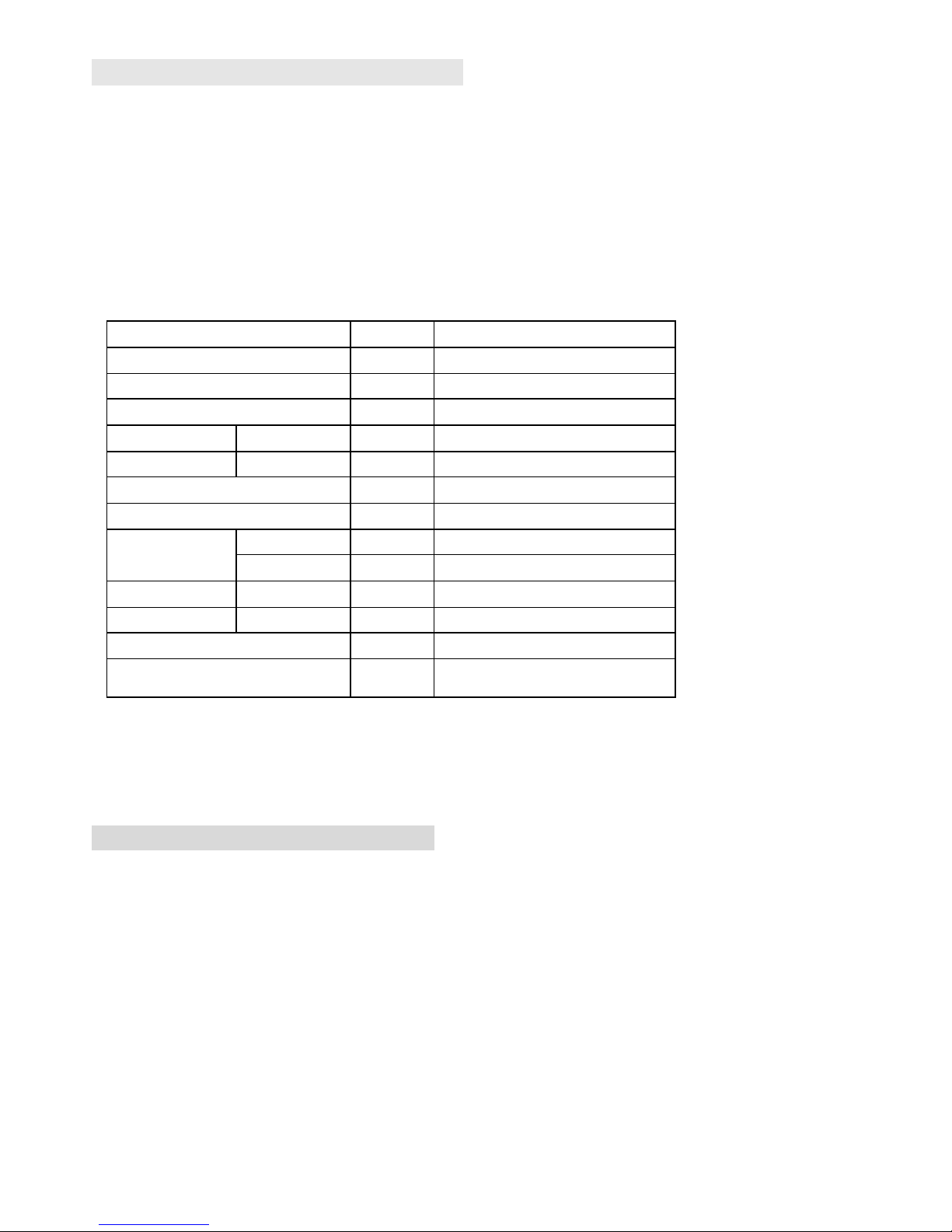
Function and Technical Specification
※ This unit offers cooling, dry, fan and sleep modes, idea for home and office use;
※ This unit is with two fan-speed levels accessible by panel control and remote control.
※ Temperature setting range of this unit is 17-30℃.
※ This unit is designed with various protection functions such as 24-hour programmable timer, auto condenser circle,
super intelligent temperature sensor and water-full control and warning etc.
Technical Specification:
Model
Unit
NPA1-10C
Power Supply
V~,Hz,Ph
110~120,60,1
Cooling Capacity
kW
2.93
Refrigerant/Charge
oz
R410A/17.63
Rated input
Cooling W 1050
Rated Current
Cooling A 10.2
Moisture Removal
L/h
1.1
Air Circulation
m³/h
380
Noise
High
dB(A)
56
Low
dB(A)
50
Body Size
W×H×D
inch
11.8×30.9×14
Package Size
W×H×D
inch
15.7×34.8×21.3
Net Weight/Gross Weight
lbs
54 /70.5
Application Area
㎡
13~18
Remark: The above cooling capacity is measured under standard working condition of ambient temperature
dry-bulb 35℃, wet-bulb 24℃ ( Indoor and outdoor, the same conditions)
Features and Identification of Parts
1. Features
※ New appearance and compact design.
※ Both horizontal and vertical louvers can be manually adjusted to enhance cooling performance.
※ Humanized pushing handle design.
※ Remote control and LED panel control, more visualized.
※ Power cord winding pillar with universal plug fixing holes to well protect the power cord.
※ High position of exhaust air outlet, easy assembly and exhaust air venting quickly.
※ 24-hour timer function, unique on/off reminding music.
※ 3-minute delay re-starting protection to compressor and other multiple protection functions.
※ Unique exhaust hose and fasteners design, convenient installation.
5
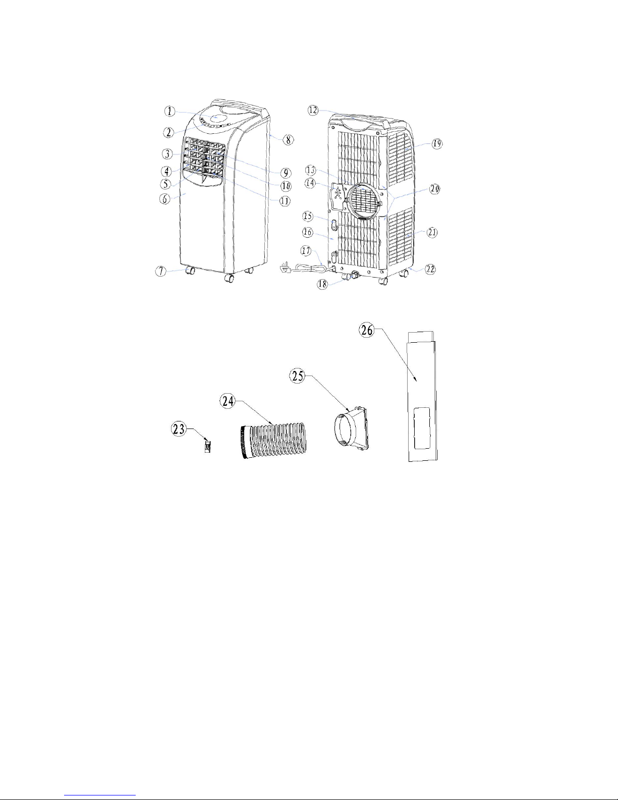
2. Identification of Parts:
1. LED Display
2. Operational Buttons
3. Vertical louvers
4. Horizontal louvers
5. Air Outlet Window
6. Front Panel
7. Universal Wheel
8. Back Panel
9. Main Vertical Louver
10. Horizontal louvers connecting rod
11. Vertical louvers connecting rod
12. Handle
13. Protective Grid of exhaust air outlet
14. Universal plug fixing holes
15. Wire winding pillar
16. Back Panel
17. Power cord
18. Drain hole and cover
19. Filter
20. Filters
21. Filter
22. Chassis
23. Remote controller
24. Exhaust hose assembly
25. Exhaust hose adapter
26. Window Seal-Plate Assembly
6
Operation and Setting
This section explains proper mobile air conditioner operation
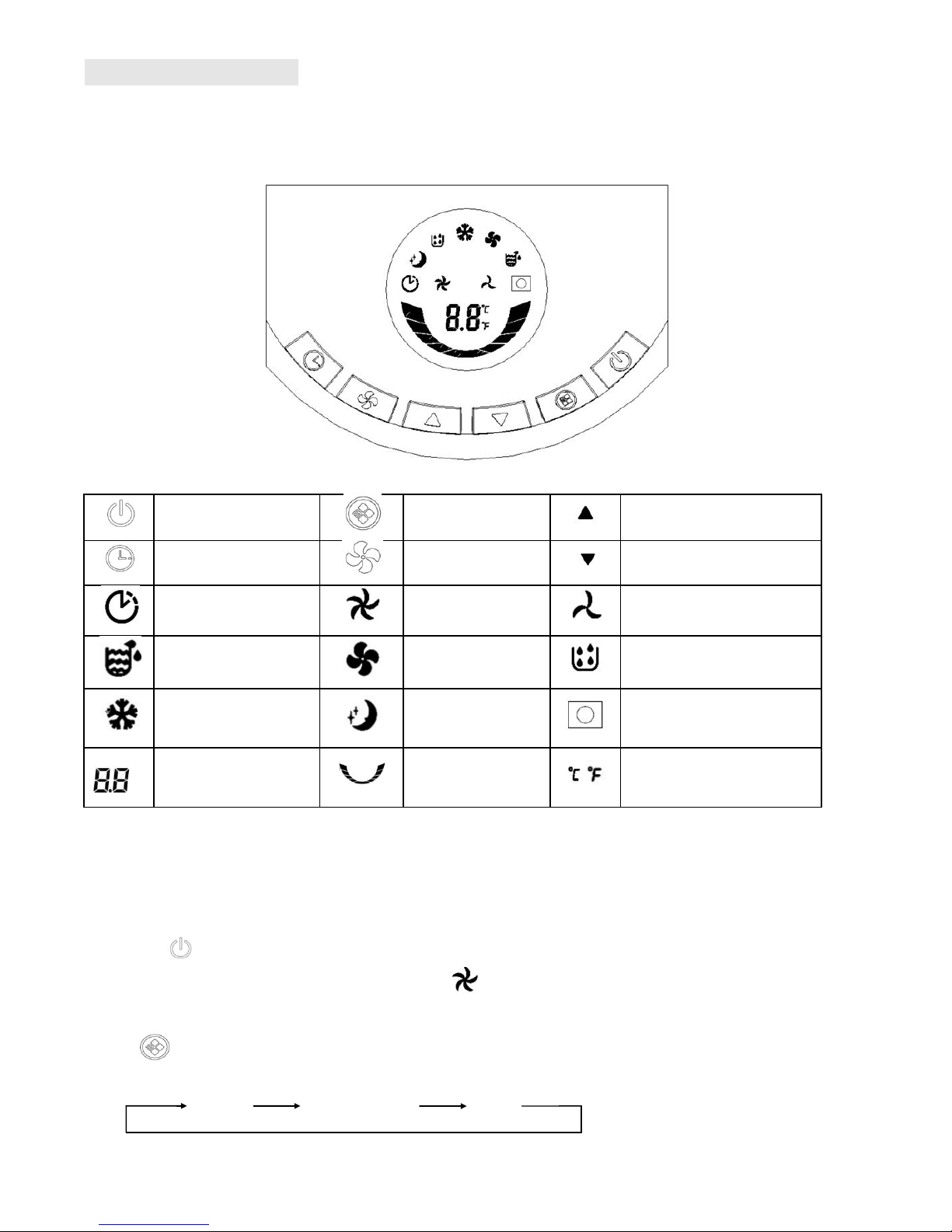
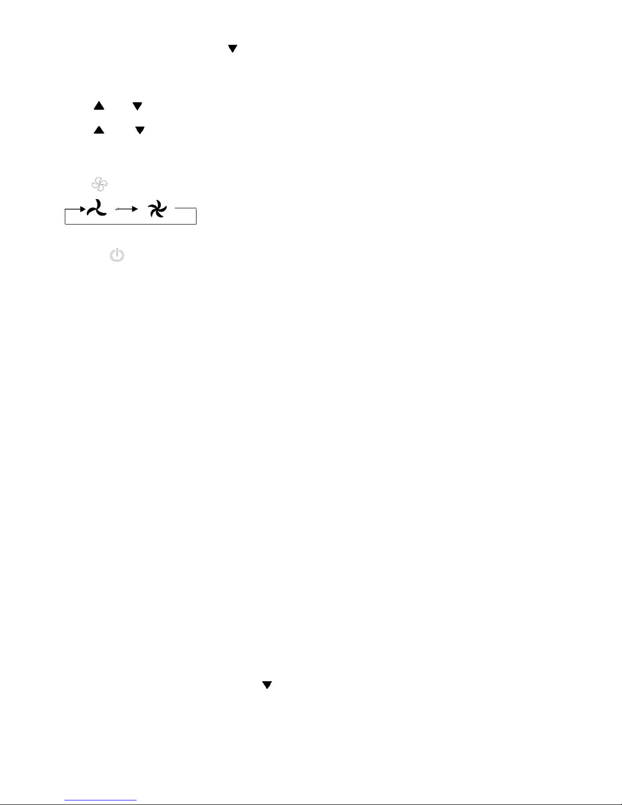
1. Control Panel
On/Off button
Mode button
Up button
Timer button
Fan speed button
Down button
Timer indicator
High speed
indicator
Low speed indicator
Water-full indicator
Fan mode indicator
Dehumidify mode indicator
Cool mode indicator
Sleep mode
indicator
Remote control signal
receiving window
LED display window
Operation indicator
Celsius/ Fahrenheit
temperature indicator
2. Control Panel Operation: This unit is with Cool, Dehumidifying, Fan and Sleep modes operations.
1) Turn on the unit.
Plug in and all indicators light up on control panel and reminding music will be on, LED display window will show
ambient temperature with range 10- 35℃, unit is standby for operation.
Press button, unit is on with reminding music sounded, and operates in Cool mode automatically,
temperature set 24℃, fan runs at high speed, and will light up.
2) Select operating mode
Press button to select a desired mode shown below, and its corresponding indicator will light up.
COOL DEHUMIDIFY FAN
7
Under cooling mode, press “Timer” + “ ” buttons together, the unit auto run in “Sleep” mode.
3) Adjust temperature
The temperature can be set within range of 17-30℃.
Press or button to increase or decrease the temperature 1 ℃ by pressing once.
Press and buttons together to convert Celsius degrees and Fahrenheit degrees and corresponding indicator
will light up.
4) Adjust fan speed
Press button to select a desired fan speed shown below
5) Stand-by
Press button once again, the unit will stop working with reminding music sounded.
Notice: working principle and function of each mode:
1. Cool mode:
When room temperature is 1℃ higher than set temperature, the compressor and fan will start to run.
When room temperature is 1℃ lower than set temperature, the compressor will stop working and fan keep
running at original speed.
The temperature can be set within a range of 17-30℃ and fan speed can be adjusted to high or low level.
Unit On/Off time can be set.
E1, E2 & E4 protection available (see Troubleshooting).
Water-full warning function.
2. Fan mode:
Fan runs at set speed, and compressor will not work.
Fan speed can be adjusted.
Room temperature will automatically show in LED display with range 10-35℃
Room temperature can’t be adjusted.
Unit On/Off time can be set.
3. Dehumidify mode:
Fan will run at low speed automatically, and fan sp eed can’t be adjusted.
Room temperature can’t be adjusted.
Room temperature will automatically show in LED display with range 10-35℃
Unit On/off time can be set.
E1、E2 & E4 protection available (see Troubleshooting).
Water-full warning function.
4. Sleep mode:
Under cooling m ode, press “Timer” + “ ” buttons together, unit will auto run “Sleep” mode.
Fan will be to low speed automatically and can’t be adjusted.
Room temperature is adjustable. Set temperature will increase 1℃ when unit running after 2 hours, increase
1℃ again after another 2-hour working, then temperature will be unchanged further.
8
Room temperature will automatically show in LED display with range 10-35℃.
On/Off time can be set.
E1, E2 & E4 protection available (see Troubleshooting).
Water-full warning protection.
5. Timer Operation
Press “Timer” button to set automatic OFF time when unit is running, Timer indicator will light up.
Unit will be off automatically when the set time is ready, and timer indicator is off, room temperature will show
on LED display window.
Press “timer” button to set automatic ON time when unit is off, Timer indicator is will light up.
Unit will turn on automatically and working at original mode when the set time is ready, timer indicator will be
off, room temperature is show on LED display window.
When press “Timer”, Timer indicator will light up, 88 in LED displ ay window will flash at 0.5 second frequency,
press or button within 5 seconds to finish timer setting, set time will flash 5 seconds for
confirmation, then room temperature will show in LED display window.
Press “Timer” to check time remained when “Timer” functio n is on; Press “Timer” twice within 5 seconds to
cancel timer.
Only final time setting is effective if repeated setting.
The time can be adjusted within a range of 1-24 hours, press or buttons, to increase or decrease 1
hour by pressing once.
Unit will not change working mode after timer set. Timer will not stop by other functions.
Timer will be ineffective if any operation from control panel or remote control to turn on or turn of the unit.
3. Remote Control Operation
The Remote control transmits the signal to system.
Button, press this button to start unit when it is energized or stop the unit when it is in operation.
Button, press this button to set unit automatic on and off time
Button, press this button to select high speed of fan running
(except dry and sleep modes)
Button, press this button to select low speed of fan running.
Button, press this button to increase temperature or timer setting.
Button, press this button decrease temperature or timer setting.
Button, press this button to make Celsius degrees and Fahrenheit
degrees interchange.
Button, press this button to select “Cool” m ode.
Button, press this button to select “Fan” mode
9
Button, press this button to select “Dry” or “dehumidifying” mode
Button, press this button to select “Sleep” function under cooling mode.
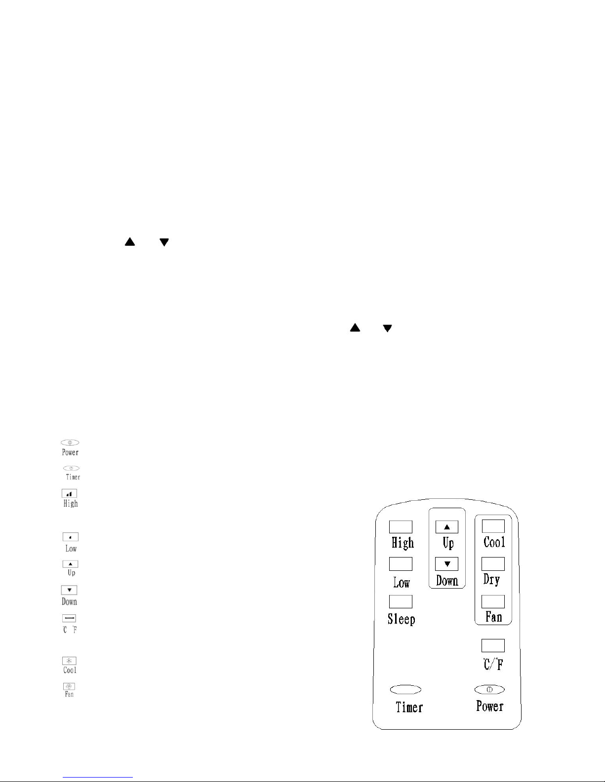
Before using your remote, install the AAA batteries into remote control.
1. Press and slide the battery cover on the back of the remote control, then you can remove the cover.
2. Insert two new alkaline AAA batteries into the battery compartment. Be sure to note the proper polarity.
3. Reattach the battery cover and make sure the locking tab clicks into place.
Notes:
Use alkaline batteries only. Do not use rechargeable batteries.
When replace batteries, always replace both batteries with new batteries, do not mix old and new batteries.
If air conditioner will not be used for an extended period of time, remove the batteries from the remote
control.
CAUTION:
If the liquid from the batteries gets onto your skin or clothes, wash it well with clean water, do not use the
remote control if the batteries have any leakage.
If you eat the liquid from the batteries, brush your teeth and see doctor. The chemicals in batteries could
cause burns or other health hazards.
Multiple Protection Functions
1. Anti-freeze protection function:
Compressor, water spraying motor will turn off under cooling mode when compressor continuously running
over 10 minutes and tube temperature (Tp) is continuously ≦2℃ for 20 seconds under cooling mode, E4 will
show in LED display window, the unit initiates the anti-frost protection process and all buttons (except for
power button) are inactive.
Once the tube temperature ≧8℃, the protection is relieved to recover into original status, and compressor
apply to 3-minute delay protection.
2. Water-full safety alarm and shut –off protection function:
Warning sounds when the water volume reached its alarm level in water tank, and unit is automatically stop
Be sure to note proper
polarity of batteries
10
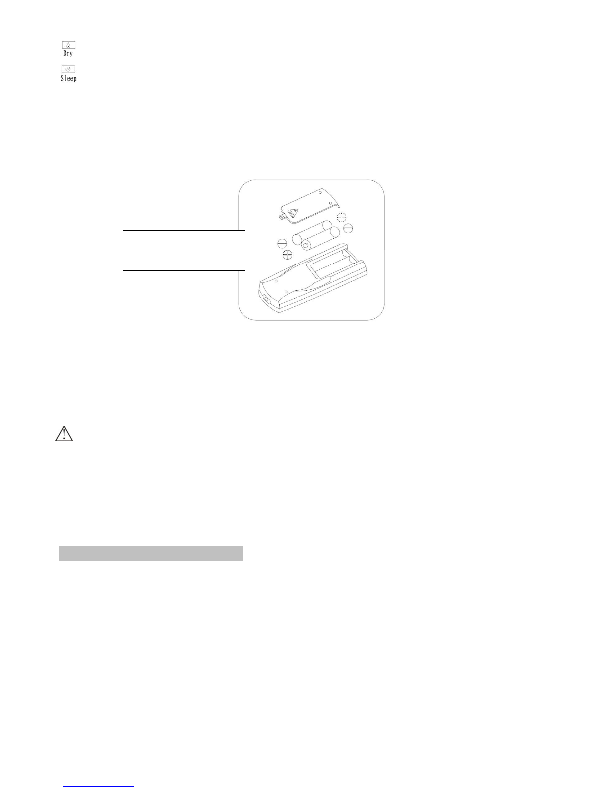
Handle
Air outlet
working, water-full mark and “FL” is flashing on LED window. You need to drain the condensate for unit
to automatically recover operation. (For more information about how to drain, r efer to the “Drainage
Instruction” please).
3. Delay protection function of compressor
This unit offers restart protection to compressor. Except that the compressor may start immediately when the
unit is energized first time, there is 3-minute delay restart protection after compressor is shut down.
Handling and Transportation
Hold the top of the air outlet in front panel with one hand and the handle at the top of back panel with another hand to
move the unit in upright position
Notes:
Do not hold the horizontal louvers by hand.
Make the unit in the upright position whatever handling or moving it.
Drain the water in the unit completely to prevent water leakage or wet the floor or carpet before handling or moving
the unit.
Installation & Adjustment
Warning:
Keep this mobile air-conditioner in upright position at least 2 hours before first installation.
Keep the unit in upright position while moving it. The air-conditioner shall be placed at flat surface.
Do not install or operate this air-conditioner in bathroom or other wet environments.
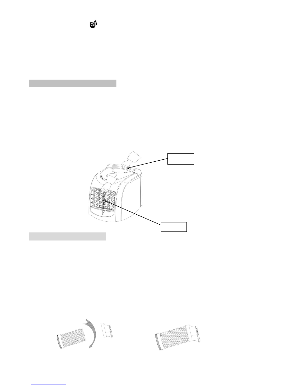
1 Installation of exhaust hose assembly.
Extend the exhaust hose, screw the round connector and adapter into exhaust hose by counter clockwise
direction.
Screw connector and adapter into right positions, at least 3 laps, to keep good connection of exhaust hose
assembly.
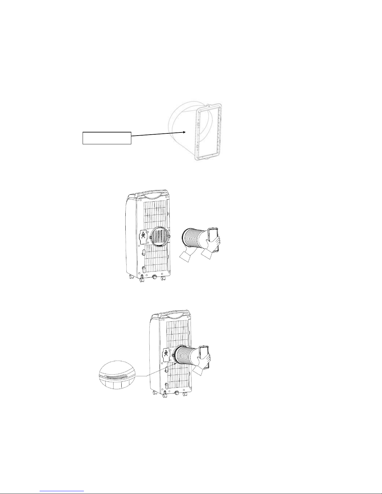
11
Slant Panel A
2 Installation of the exhaust hose assembly into unit
Determine window seal-plate position, vertical or horizontal direction.
If window seal-plate will be in horizontal position, the slant panel A of adapter should be up towards.
If window seal-plate will be in vertical position, and will be at left side of window, the slant panel A of adapter
should be at right direction
If window seal-plate will be in vertical position, and will be at right side of window, the slant panel A of adapter
should be at left direction.
Take two ends of exhaust hose and adapter assembly.
Put front end of exhaust hose onto jugged position of exhaust outlet of back panel.
Hold the unit by one hand, carry the exhaust hose assembly with another hand and push it into unit gently,
fasteners will lock automatically.
 Loading...