

Page 1
GLGBAL
WF976
CYLINDER BED
COMPOUND
LOCKSTITCH
OPERATION I INSTRUCTION I PARTS MANUAL
SEWING MACHINE
TWIN
FEED
NEEDLE,
Page 2
Content
Operation
I.
Briefintroduction
2. Main
3.
4.lnstalling
5.
6.
7.
8.
9.
I
0.
II.
12.
I 3.
I 4.
15.
16. Winding adjustment.
I 7.
I 8.
I 9.
20.
21 . Adjusting
22.
23.
24.
25.
specification
Installing
Connecting
Installing
Installing
Installing
Operation
Lubrication
Trial
run
Installing
Coordination
Threading
Adjusting
Setting
Adjusting
Function
Adjusting
Timing
Adjusting
Relationship
Removing
Instruction
....................................
....................................................................................................
the
machine
the motor.
the clutch to the pedal..
the
presser
the
bobbin
the
thread
preparation
...........................................................................................................
................................................................................................................
the
needle
among
the
needle
the
tension
the stitch length and reverse
the
pressure
of
the
safety
the lift
the
feed adjustment..
the
and
amount
position
timing
between
installing
--·············--··············································-'
...............................................................................................
..................................................................................................
............................................................................
foot lift
winder.
spool
...............................................................................................
...............................................................................................
needle,
thread
of
...............................................................................................
between
control
......................................................................................
stand
thread
.....................................................................................
bobbin
of
presser
c I utch
....................................................................................
of
presser
of
the feed
.........................................................................................
the
rotating
the
rotating
plate
..................................................................
.................................................................................
and
thread and
sewing
foot
.......................................................................
foot with
dog
.......................................................................
needle
and
hook and hook
hook
materials
rotating
................................................................
......................................................
needle
..............................................................
thread
walking
hook
separator
...........................................
presser
....... ,
foot..
...........................
......................................
........................................
I
I
2
2
2
3
3
3
.4
.4
.4
5
5
5
6
7
7
7
8
8
8
9
9
9
Parts
1.
2.
3.
4.
5. Feed
6.
7.
8.
Manual
Arm
and
Upper
Presser
Lower
shaft
Upper
Threading
Accessories
bed
.......................................................................................................
shaft
and thread take-up parts
bar
and draw bar parts
shaft
and
rotating
parts
..................................................................................................
feed and
presser
parts
..................................................................................................
........................................................................................................
..............................................................................
hook
foot lifter parts
....................................................................
parts
.....................................................................
.................................................................
I 0-11
l2-13
14-1
16-1 7
18-19
Z0-21
22-23
24-25
5
Page 3
Operation
Instruction
Page 4
1.
Brief
This
series
rotating
seam.Upper
teeth-type
lever-type
series
avoid
occurs.
compound
with
needle
weight
They
products.
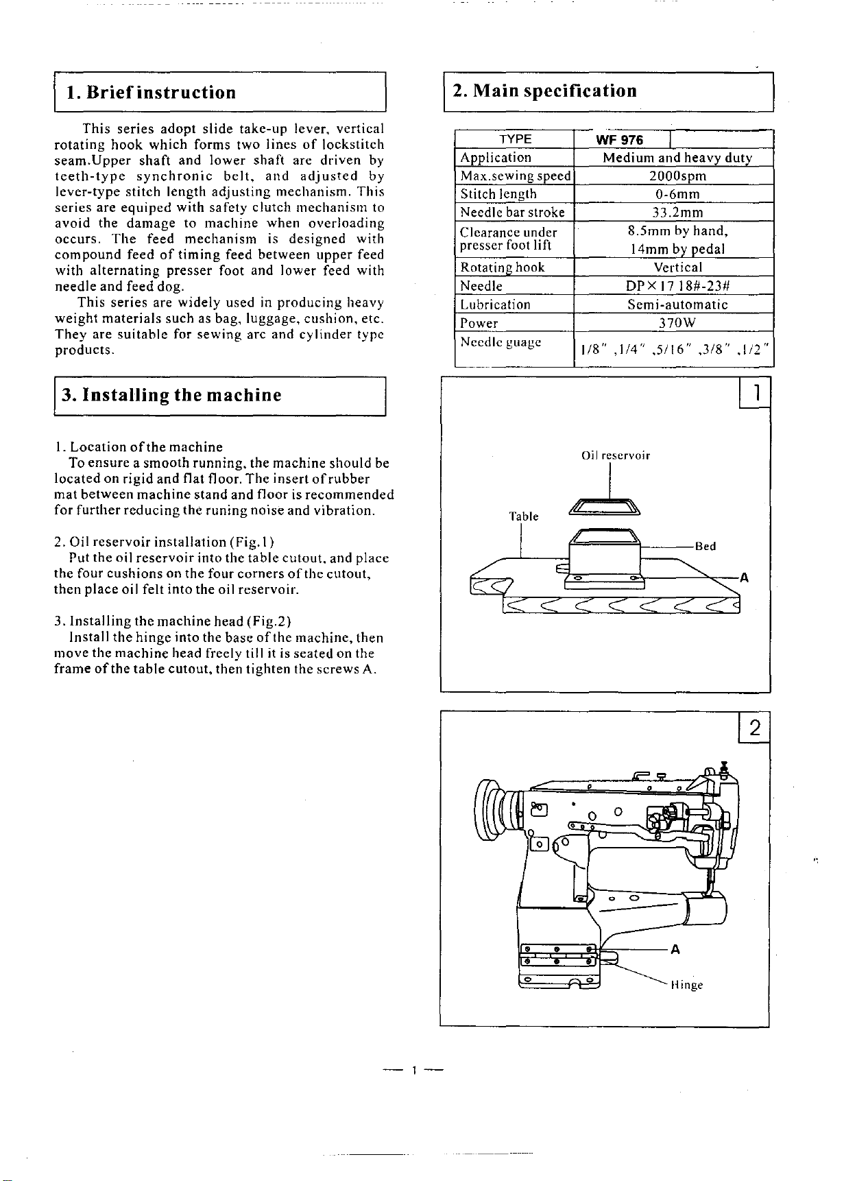
J3.
I.
To
located
mat
for
Oil
2.
Put the oil
the four
then
3.lnstalling
Install
move
frame
hook
are
the
The
alternating
and
This
series
materials
are
suitable
Installing
Location
ensure a smooth
on
between
further
reservoir
cushions
place
the
the
machine
of
the
instruction
adopt
which
shaft
synchronic
stitch length
equiped
damage
feed
feed
of
feed dog.
are
of
the
rigid
and flat floor.
machine
reducing
installation
reservoir
oil felt into the oil reservoir.
the
machine
hinge
table
slide
take-up
forms two lines
and
lower
adjusting
with safety clutch mechanism to
to
machine
mechanism
timing
presser
widely
such as bag, luggage,
for
sewing
the
machine
machine
running,
stand
the
runing
into
on the four
into the
head freely till it is
cutout,
shaft
belt,
foot and lower feed with
head
then
and
mechanism. This
when
is
designed
feed between
used in
and
(Fig. I)
the
base
producing
arc and
the machine should be
The
insert
floor is
noise
and vibration.
table
cutout,
corners
tighten
(Fig.2)
of
the
of
lever. vertical
of
lockstitch
are
driven
adjusted
overloading
upper
cushion,
cylinder
of
rubber
recommended
and
the
cutout,
machine,
seated
the screws A.
by
by
with
feed
heavy
etc.
type
place
then
on the
2. Main
Application
Max.sewing speed
Stitch length
Needle bar stroke
Clearance under
presser foot lift
Rotating hook Vertical
Needle
Lubrication
Power
Needle
specification
TYPE
guagc
1/8" , I
WF976
Medium and heavy duty
DPX
/4"
I
2000spm
0-6mm
33.2mm
8.5mm by hand,
14mm by pedal
17
18#-23#
Semi-automatic
370W
,5/16"
--
Oil
reservoir
~
/
IC
TTe
<
./
IS:
c:
E
"
0
c::
c::
...
<
.::::::: .:::::::
,3/8"
Bed
~
I ·o"
•
1.:..
lJ_
~A
<j
-1-
Page 5
A
,4.
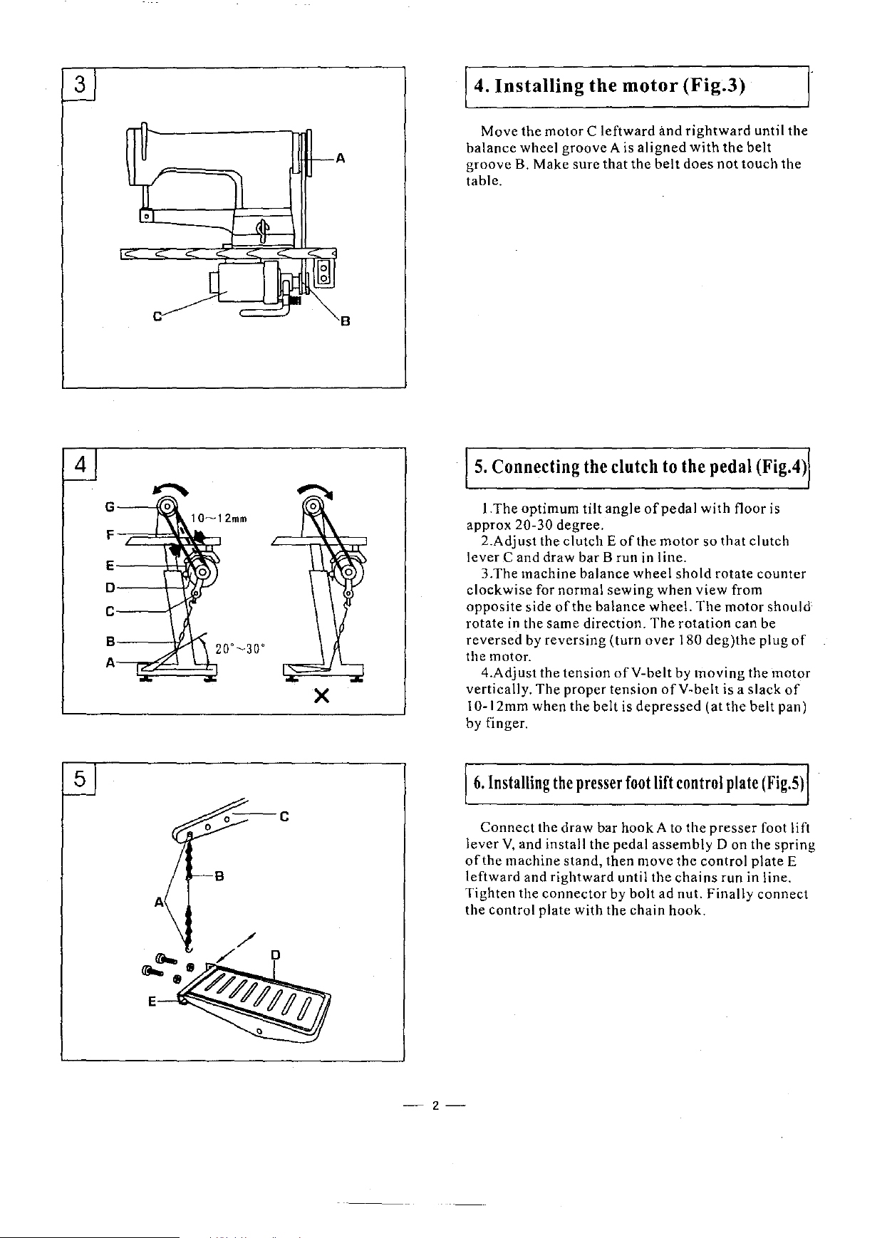
Installing
Move
the
motor
balance
groove B. Make sure that the
table.
wheel groove A is
the
motor
C leftward
aligned
and
belt
(Fig.3)
rightward
with
the
does
not
r
until the
belt
touch the
c
1
0-12mm
E---1+'~
D'---+----1-
C----1'
s.---tr...1r"\
A~~d::b
X
B
5.
Connecting
!.The
optimum
approx
lever C and draw
clockwise
opposite
rotate in the same direction.
reversed
the motor.
vertically. The proper
I 0-12mm when the
by finger.
20-30 degree.
2.Adjust the clutch E
3.The machine balance wheel
for normal
side
by
4.Adjust the tension
the
clutch
tilt
angle
of
barB
run in line.
sewing
of
the balance wheel.
reversing
(turn
ofY-belt
tension
belt
is
the
depressed
to
of
pedal
motor
shold
when
The
over
by
ofY-belt
the
pedal
with
so that clutch
rotate
view
from
The
motor
rotation
180
deg)the
moving
is a slack
(at
the
(Fig.4)
floor is
counter
should
can
be
plug
the motor
belt
of
of
pan)
5
-2-
6.
Installing
Connect
lever
V,
of
the machine
leftward and
Tighten the
the control plate
the
the draw bar hook A
and install the pedal assembly
rightward
connector
presser
stand,
with
foot
lift
control
to
then move the
until the
by bolt ad nut. Finally
the chain
chains
hook.
the
presser
control
plate
Don
run in line.
(Fig.S)
foot lift
the
spring
plate
connect
E
Page 6
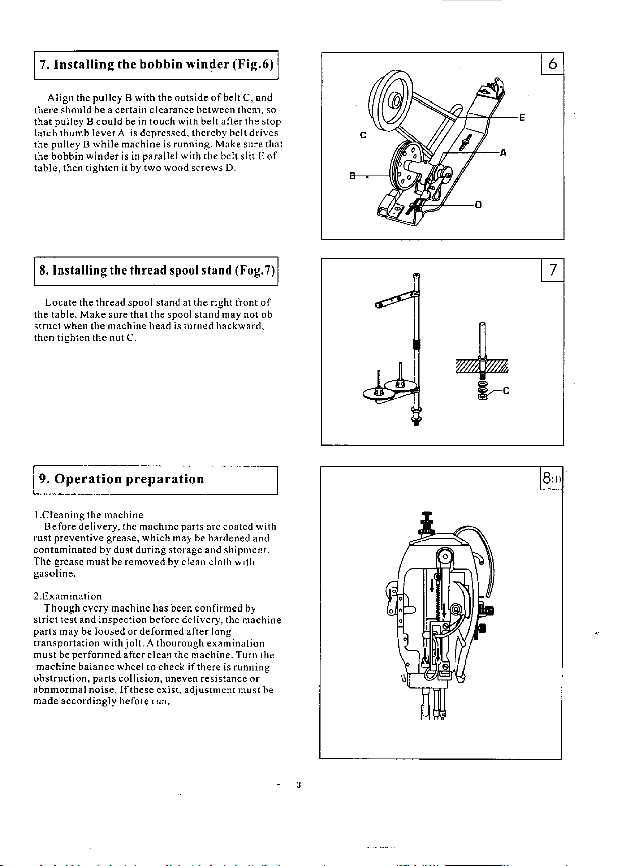
,7.
Installing
Align
the
there
should
that
pulley B could
latch
thumb
the
pulley B
the
bobbin
table,
8.
Installing the thread spool stand (Fog.
then
winder
tighten
the
bobbin
pulley B with
be a
lever
while
certain
A is
clearance
be in touch with belt
depressed,
machine
is in parallel with the
it by two
winder
the
outside
is running. Make sure that
wood
of
between
thereby
screws D.
(Fig.6)
belt
C, and
them,
after
belt
belt
slit E
so
the stop
drives
of
7)
I
6
e,~-
Locate
the
struct
then
19.
!.Cleaning
Before
rust
contaminated
The
gasoline.
the
table.
Make
when
the
tighten
Operation
the
delivery, the machine parts are
preventive
grease
must
thread
the nut C.
spool
sure
that
machine
preparation
machine
grease,
by
dust
be
removed
stand at the right front
the spool stand
head is
which may be hardened and
during
turned
storage
by
clean
may
backward,
coated
and
shipment.
cloth with
not ob
of
with
2.Examination
Though
strict
parts
transportation
must
machine
obstruction, parts
abnmormal
made
every
test
and
inspection
may
be loosed
with
be
performed
balance
noise.
accordingly
machine
wheel
collision,
If
before
has
been
before
or
deformed
jolt. A thourough
after
clean
to
check
uneven resistance or
these
exist,
run.
confirmed
delivery, the machine
after
long
examination
the
machine. Turn the
if
there
adjustment
by
is
running
must be
-3-
Page 7
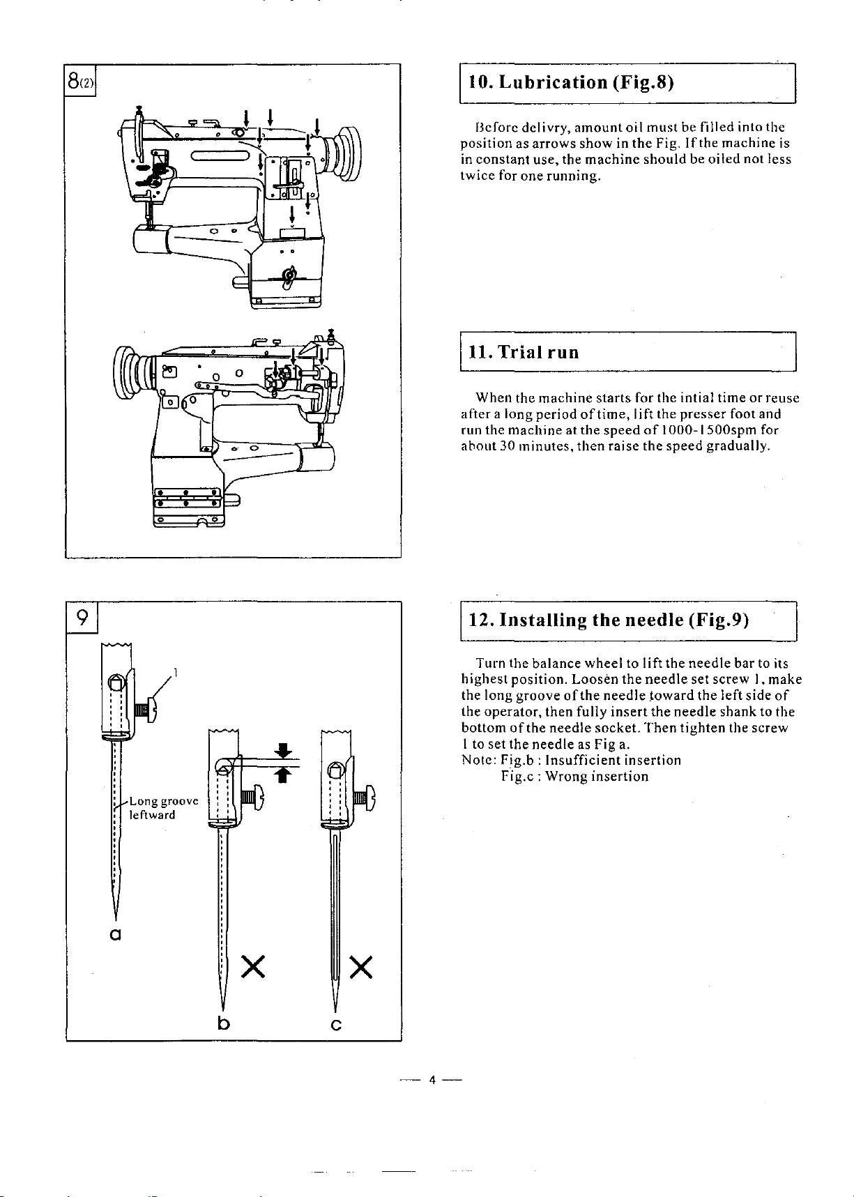
10.
Lubrication
(Fig.8)
Before dclivry,
position
in
twice
as
arrows
constant
use, the
for one running.
11. Trial run
When
the
machine
after
a long
run the
about
period
machine
30
minutes,
amount
show
machine
starts
of
time,
at the
then
oil
must
in
the
Fig.
should
for the intial time
lift
the
speed
of I 000-1500spm
raise
the
speed
be filled into the
If
the
machine
be
oiled
not less
or
reuse
presser
foot and
for
gradually.
is
9
Long groove
leftward
a
b
X
c
X
12.
Installing
Turn the
highest
the long
the
operator,
bottom
I to
set
Note:
Fig.b:
Fig.c:
balance
position.
groove
then
of
the
needle
the
needle
Insufficient
Wrong
the
wheel to
Loosen
of
the
fully
socket.
as Fig a.
insertion
needle
the
needle
insert
insertion
lift
the
needle
toward
the
needle
Then
(Fig.9)
needle
set screw I, make
tighten
bar
to its
the left side
shank
to the
the
screw
of
-4-
Page 8
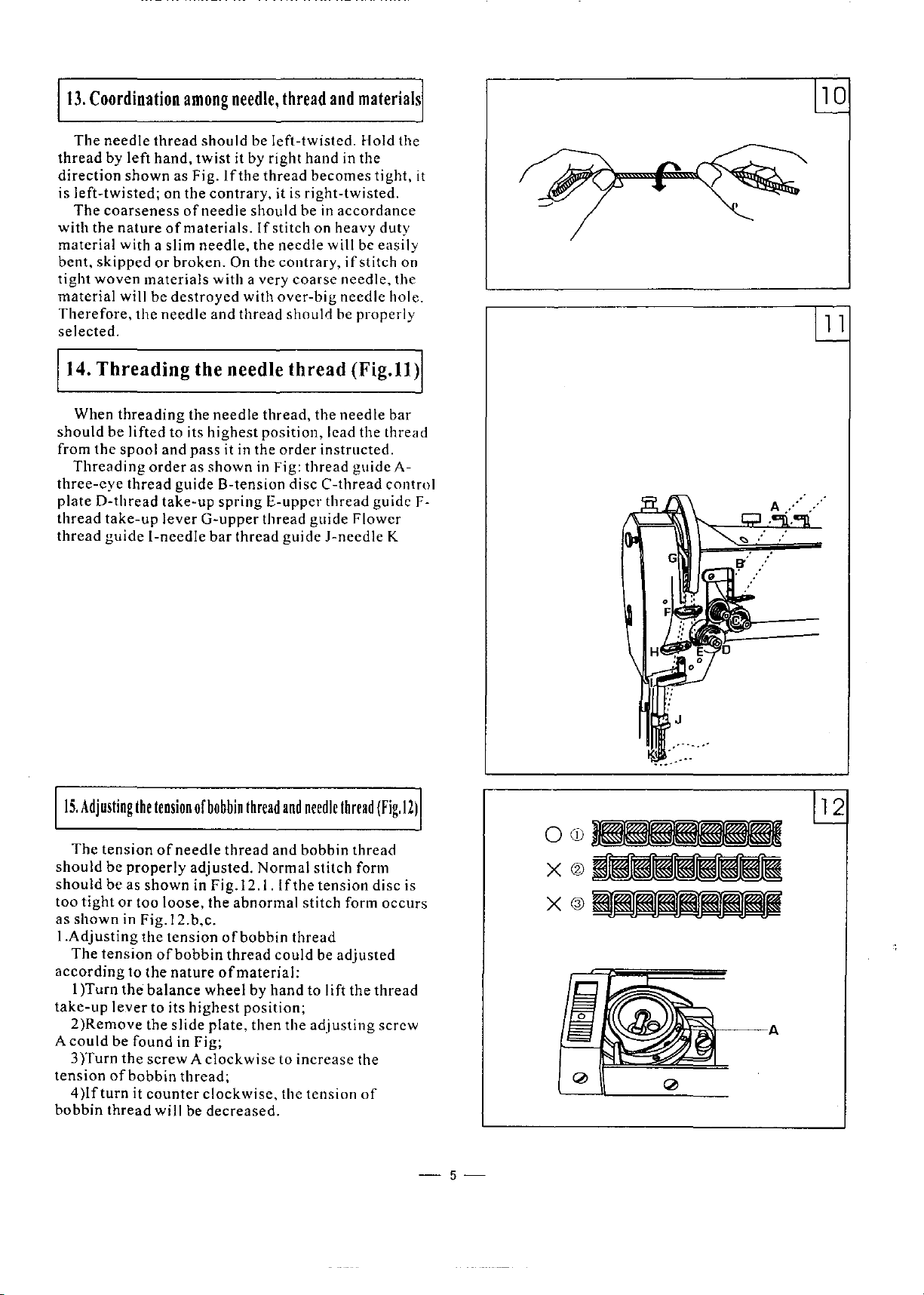
13.
Coordination
The
needle
thread
direction
is
with
material
bent,
tight
material
Therefore,
selected.
should
from
three-eye
plateD-thread
thread
thread
by
left
shown
left-twisted;
The
coarseness
the
nature
with a slim
skipped
woven
will
the
14.
Threading
When
threading
be
lifted to its
the
spool
Threading
thread
take-up
guide
materials
among
thread
hand,
as
on the contrary, it is
of
ofmaterials.
or
broken.
be
destroyed
needle
needle,
should
twist
Fig.
needle
needle,
be
it by right
If
the
should
the
On the contrary,
with a very
with
and
thread
If
the needle
the
needle
highest
and
pass
it in the
order
as
guide
take-up
lever
!-needle
shown
G-upper
bar
in Fig:
B-tension
springE-upper
thread
thread
left-twisted.
hand
thread
becomes
right-twisted.
be in
stitch
on heavy duty
needle
coarse
over-big
should
thread
thread, the
position,
order
instructed.
thread
disc
C-thread
thread
thread
guide
guide
J-needle
and
materials
Hold the
in the
tight,
it
accordance
will be
lead the thread
if
stitch on
needle,
needle
be
properly
(Fig.
needle
guide A-
guide F-
Flower
easily
the
hole.
II)
bar
control
K
1 1
15.
Adjusting
The
tension
should
should
too
as
!.Adjusting
according
take-up
A
tension
bobbin
be
be
tight
or
shown
The
tension
I )Turn
lever
2)Remove
could
be
3)Turn
of
4
)lfturn
thread
the
tension
of
bobbin
of
needle
properly
as
shown
too
in
Fig.l2.b,c.
the
to
the
found in Fig;
the
bobbin
it
adjusted.
in
Fig.l2.1.
loose,
the
tension
of
bobbin
the
nature
balance
to its
the
screw A clockwise
counter
will be
wheel
highest
slide
thread;
clockwise,
plate,
decreased.
thread
thread
Normal
abnormal
of
bobbin
thread
of
material:
by
position;
then
and
and
If
the
thread
could
hand
the
to
the
needle
thread
bobbin
stitch
tension
stitch
be
adjusted
to lift the
adjusting
increase
tension
thread
form
disc is
form
thread
the
of
(Fig.l2)
occurs
screw
-5-
12
OCD
X®
X©
Page 9
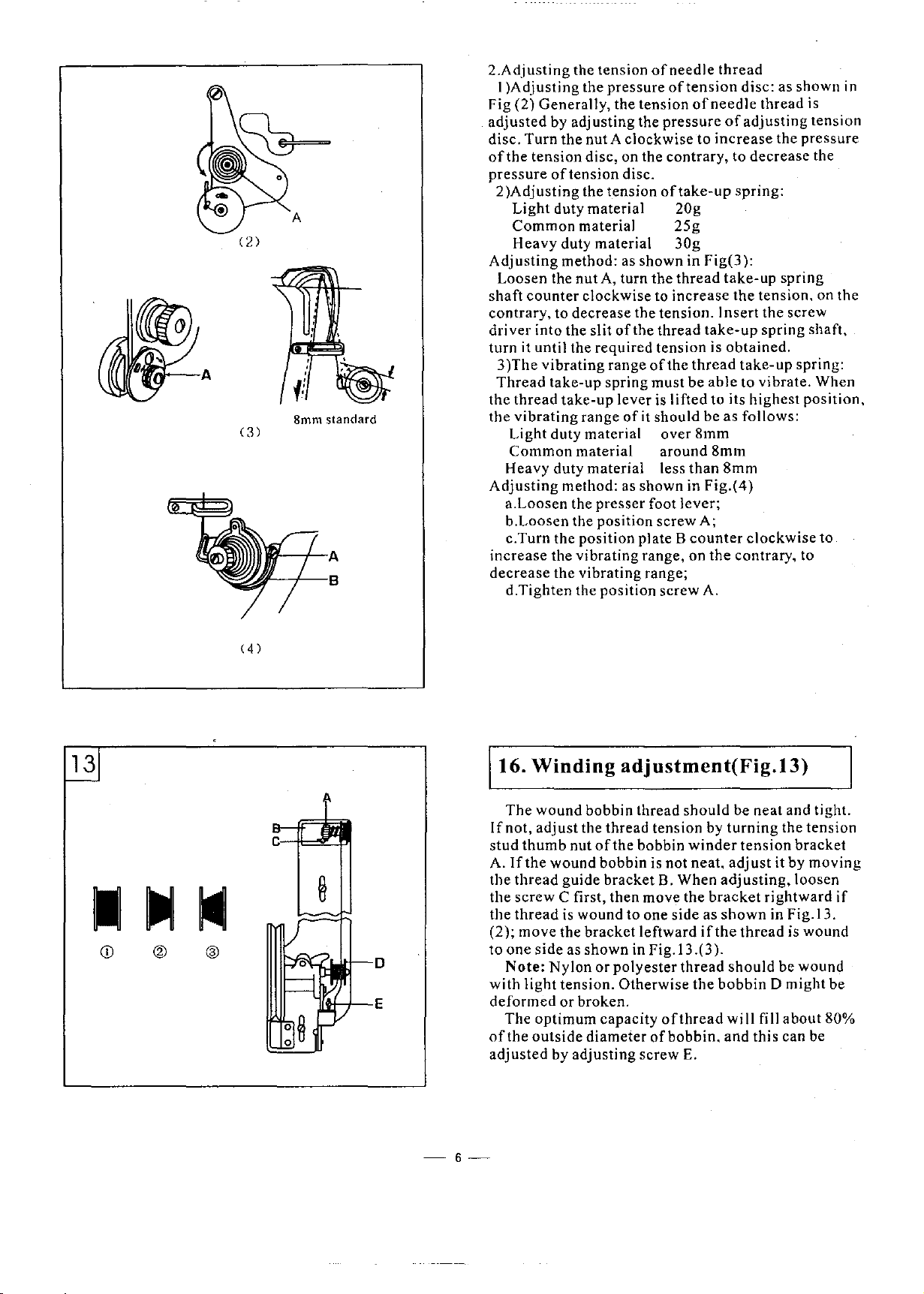
2.Adjusting
I
)Adjusting
Fig
(2)
adjusted
disc. Turn
of
the
pressure
2)Adjusting
Light
Common
Heavy duty material
Adjusting
Loosen the
shaft
counter
contrary, to decrease the tension. Insert the screw
driver
turn
it
3)The
Thread
the
thread
the
(
3)
8mm standard
vibrating
Light
Common
Heavy duty material less
Adjusting
a.Loosen
b.Loosen the position screw
c.Turn the
increase
decrease
d.Tighten the position screw A.
the tension
the pressure
Generally, the tension
by
adjusting
the
nut A clockwise to
tension
into the
until the required tension is
disc, on the contrary, to
of
tension disc.
the tension
duty material 20g
material 25g
method: as shown in
nut
A, turn
clockwise to increase
slit
vibrating
take-up spring
take-up
range
duty material over
material around 8mm
method: as shown in
the
presser
position
the
vibrating
the
vibrating
of
needle
of
tension
of
the
pressure
of
take-up
30g
Fig(3):
the
thread
of
the thread
range
of
must
lever is lifted to its
of
it
should
foot
plate B
range, on
range;
the
be
than
lever;
counter
take-up
thread
be
8mm
Fig.(4)
A;
thread
disc: as shown in
needle
increase
able
the
thread is
of
adjusting
the pressure
decrease
spring:
take-up
the
tension. on
spring
obtained.
take-up
to vibrate. When
highest
as
follows:
8mm
clockwise
contrary, to
tension
the
spring
the
shaft,
spring:
position.
to
13
CD
®
( 4 )
16.
Winding
The
wound
If
not,
adjust
stud
thumb
A.
If
the
the
thread
the
screw
the
thread
(2); move the
to
one
Note:
with
light
deformed
The
of
the
adjusted
nut
wound bobbin is not neat,
guide
C first, then move the
is wound to one
side
as
Nylon
tension.
or
optimum
outside
by
adjusting
adjustment(Fig.13)
bobbin thread
the thread tension by
of
the
bobbin
bracket
bracket
shown
broken.
diameter
in Fig. I 3
or
polyester
Otherwise
capacity
should
winder
B. When
side
leftward
thread
ofthread
of
bobbin.
screw
E.
bracket
as
if
.( 3 ).
the
be neat and tight.
turning
adjust
adjusting,
shown
the
should
bobbin
will
and
the tension
tension
it by
rightward
in Fig. I 3.
thread
is wound
be wound
D might be
fill
about
this can be
bracket
loosen
moving
if
80%
-6-
Page 10

17.
Setting
the
stitch
length
and
reverse
sewing
(Fig.l4)
14
Stitch
length
length
figure on
indicates
obtained
forward
reverse
accordance
materials
screw
pressure.
pressure
decrease
length
regulating
adjusting
feed
18.
Adjusting
Pressure
clockwise
the
the
when
sewing
to
While light materials to be sewn, turn the
regulating
the
could
be
adjusted
nut. When
position
stitch
stitch
reverse
can
lever
is released.
the
on
presser
with materials to be sewn.
be
sewn,
as
pressure.
block
length dial
length. Reverse
feed
be restored
pressure
foot is to be
turn
shown in
screw
by turning the stitch
the
scale on
is aligned with
plate,
sewing
lever
is
automatically
of
presser
adjusted
the
pressure
Fing.l5
counter
clockwise
the
stitch
some
then the figure
can be
depressed
foot
If
regulating
to increase the
and
when
(Fig.
in
heavy
to
IS)
Counter
clockwise
\
l
Clockwise
19. Function
When
the
thread
because
the
belt
load on
the
power
outside,
swtichs
hand,
balance
the
should
counter
its
synchronic
arrow on
synchronic
of
abnormal
clutch
When the arrow
center
button.
When
highest
will
wheel shaft. Turn
the
clutch.
of
the
on the
the
power
off, turn the
when
the
wheel
the
clutch
be
re-installed.
clockwise
position,
belt
the
position
belt.
of
the safety clutch (Fig.16)
is twisted into the
operation,
automatically
the
of
the
lower
clutch;
when
is stronger. When the safety clutch
balance
stop
plate
to make it switch on again, then loosen
switchs
to lift the
meanwhile,
wheel
should
plate. Then install the
get
eccentric
eccentric
shaft, it
the
arrow is
wheel
stops
off. the
First, turn the
thread
be
rotating
the
spring
off
the
pin to adjust the
pin is
indicates
toward
clockwise
the
wheel,
synchronic
balance
take-up lever to
the red arrow on the
aligned
hook
plate
bushing
aligned
the
weakest
the
by
turn the
belt
wheel
with
the
on
of
with
right
Arrow
Eccentric
l
pin
Red arrow
Position plate arrow
-7-
Page 11

17
20.
Adjusting
the
lift
amount
of
presser
foot
with
walking
presser
foot
(Fig.l1)
l
B
d>/lf'>!!',s:!-=
0.
Bmm
~l.Omm
~1.2mm
,~1.5mm
The lift
with
Loosen the wing
B between wing nut A
Shorten the
amount; widen the
lift amount.
the balance wheel
collision.
21.
When
the height from the teeth
plate should be in
When
the
duty materials, the
when sewing
about
the height
position
A,
and
then tighten the screw.
amount
presser
center
Adjusting
the
sewing
height
should
I mm, when
should
of
feed dog, first
move
of
walking
foot
can
be
nut A and
and
distance
center
After
adjustment,
slowly
the
position
feed
dog
is
accordance
heavy
common
it
duty
be
about
height
sewing
be
about
vertical1y to reach its required height,
presser
adjusted
adjust
the
presser
B to
distance
tighten
to
check
of
the
raised
materials,
to its
point
to the
with
materials
1.2mm. when
should
extra
I.Smm.
loosen
foot
as follows:
its
center
foot lift shaft.
increase
B to
decrease
the
if
there
feed
dog
highest
surface
the
materials.
such
be
about
the
height
heavy
duty
when
the feed
together
distance
the
lift
the
screw, turn
is parts
(Fig.
IS)
position,
of
needle
as leather,
sewing
adjusting
dog
light
0.8mm.
should
materials,
screw
be
the
l
B
-8-
122.
Timing
!.Standard
When the feed
needle
move downward,
and is aligned
body.
position
2.Installing the feed
cover, turn the
right hand, the front oil A
basic point, when the A is
dog two screws
plate
Adjustment
of
First, adjust the
feed
position
dog
is
just
and
begin
feeding,
close
to
with
the
needle
can
be
feed dog cam and
dog
stitch
balance
Bare
wheel
symmetrical.
adjustment
above
the
surface
the
needle
the
surface
hole on
adjusted
vibrating
length
counter
hole
on
vertically
by
to
0, open
upper
of
the
adjusting
clockwise
upward.
(Fig.19)
of
should
needle
shaft
shaft
plate
feed dog
the
crank.
the
upper
is the
feed
I
by
Page 12

23.
Adjusting
the
timing
between
needle
and
rotating
hook
(Fig.20)
2
Turn the
lowest
from its
coincided
clearance
hole
move
then
side
be
position.
lowest
is
approx
the
tighten
clearance
0-0.05mm.
24.
Relationship
balance
position,
with
the
between
2mm.
needle
the
between
between
wheel to
Then
center
hook
bar
vertically
screw
the
lower
the needle bar to its
when the
hook
point
!fit
is not, loosen the screw A.
A. when
hook
rotating
needle
point
line
of
the needle. The
and upper end
to its
adjusting,
point and
hook
and
is lifted 2.5mm
should be
required
needle
hook
separator
of
needle
position,
note that the
should
(Fig.20)
A
B
0.0511111
21
!.Remove
2.Turn
distance
A is
3.Loosen
between
(Adjust
4.After
25.
If
the
it as follows:
I.Lift
remove
2.Remove
rear
}.Release
separator
4.Release
the
between
obtained;
separator
in
accordance
adjustment,
Removing
rotating
the
the
needle;
presser
B;
D·
5.Turn the hook
6.Release
Installing
l.Install
above;
2.Note
removing
the
the
that
direction.
the
slide
balance
the
the
adjusting
and
and
installing
hook
needle
the
slide
plate
and
the
adjusting
the
screw C and
base
the
screw
rotaing
rotating
installing
plate;
wheel and stop when the
hook
separator
screw B so that
rotating
with the
tighten
the
the
is
damaged
bar to its highest position and
plate,
needle plate, front and
bobbin;
screw
remove the
E slightly and take it out;
and
take
hook:
hook
in the reverse process
direction
and
hook is
thickness
rotating
during
out the hook body
0.15mm.
adjusting
hook
sewing, replace
A,
remove
is the
same
biggest
rotating
the
clearance
of
materials);
screw B.
(Fig.22)
the
presser
with
hook
plate
F.
=
IIIII o 1111
B
D
E
0.
1511111
22
.,
-9-
Page 13

Parts
Manual
Page 14

1. Arm and
bed
32
26
JJ;-~~25
I
4
3
49
-10-
Page 15

1.
Arm
No.
and
bed
Part
number
Name
Qt.
Remark
I
2
3
4
5
6
7
8
9
10
11
12
13
14
15
16
17
18
19
20
21
22
23
24
25
26
27
28
29
30
31
32
33
34
35
36
37
38
39
40
41
42
43
44
45
46
47
48
49
50
51
52
53
9!WF2-001
91WF2-002
22WF2-003
37T4-407
22WF2-004
37T4-409
22WF2-006
37T4-411
22WF2-020 Screw
91WF2-003
89WF2-006
89WF2-005
49WFI-006
89WF2-004
91WF2-004 Safety guard I
49WF2-009 Screw 2
91WF2-005
49WF2-012
49WF2-013 Seal gasket
49WF2-014
49WF2-015 Spring
7KT2-020
49WF2-016 Column
!3WF6-008
49WF2-017 Pin
49WF2-018
49WF2-019
17T5-016
49WF2-020 Pin
49WF2-021
16WF2-038
16WF2-059
90WF2-005 Trade mark
91WF2-006
16WF2-053
I
KTI-005
91WF2-007
91WF2-008
91WF2-009
91WF2-0IO
91
WF2-0
9!WF2-012
WF2-0 13
91
91WF2-014
22WF2-007
91WF2-015
16WF2-035
91WF2-016
91 WF2-0 17
91WF2-018
22WF2-018
11
Cylinder bed
Arm
Base
Hinge 1
Screw
Connecting hook I
Connecting hook screw assembly I
Washer I
Face plate I
Face plate hinge assembly
Hinge
screw
Rubber
Spring
Upper
Screw
Oil
Washer
Screw
Spring
Column
Screw
Oil
Oil
plug I
plate
cover
window
tube
wick
Oil retainer
Screw
Trade mark
Trade mark
Rivet
Trade mark
Needle plate
Screw
Slide
plate
assembly(L)
Slide
plate
assemblyO
Right
presser
Left
presser
presser
Right
Left
presser
Screw
Connecting presser plate
Screw
Safety ring
Connecting holder
Screw
Washer
Connecting
plate (long)
plate (short)
foot (long)
foot (short)
10
pin
I
I
1
6
I
1
8
I
I
8
1
I
I
I
I
I
I
I
I
I
I
I
I
I
I
I
I
4
I
I
2
I
I
I
I
I
I
8
2
I
I
2
2
2
11/64'X32
9/64'X40
ll/64'X40
--11-
Page 16

2.
Upper
shaft
and
th
read
take
_
-up
- s
part
14
12
4 3
7
s--LPf
6
r
1'
11
8
t
0.
i
10
J
20~
rl
18
-12-
Page 17

2.
Upper
shaft
No.
1
49WF!-003
2 49WF!-004
3
4
91WF!-002
5 215029
6
7
l6WFl-011
8 16WF!-Ol5
9 16WF1-016
10
16WFI-017
I I
12
13
14
15
16
17
16WF1-0IR
16WF1-019
16WF1-020
16WFI-021
16WF1-022
22WF1-005
18
19 103565
20 16WF1-025
21
22
22WF1-006
16WF1-004
23 16WF1-026
24
25
22WF1-047
22WF1-048
26
27
16WF1-029
28 22WF1-043
29
30
31
22WFI-011
22WF1-045
22WF1-046
32 037473
33
13WF
34 13WFl-078
35
16WF1-040
36 91WF1-017
37 22WF1-041
38 16WF1-019
39
22WF1-042
and
Part
1-077
thread
number
take-up
----
cad
Thr
Scr
Oil
Thr
Sli
Oil
Ne
Ne
Pos
Scr
Oil
Ne
Pos
Scr
Spa
Scr
Up
Oil
Fro
Oil
Mi
Scr
Re
Re
Scr
Rc
Ret
Syn
Scr
Scr
Scr
Bal
Scr
Scr
Scr
Syn
Mi
Scr
Nut
take-up
ew
wick
cad
take-up
de
blcok
wick
edle
bar
edlc
bar
ition
screw
ew
wick
cd]c bar crank
it
ion
screw
cw
ccr
ew
per
shaft
wick
nt
bushing
felt
ddle
bushing
ew
arbushing
ar
bushing
ew
ar
bushing
awmg
chronic
ew
ew
(short)
ew
(long)
a
nee
wheel
ew
ew
ew
chronic
ddle
bushing
ew
parts
Name
link
crank
gasket
bearing
ring
belt
belt
lever
lever
pin
wheel
gasket
pin
sh
aft
------
-
Qt.
Remark
1
1
1
1
I
1
1
1
1
I
1
1
1
1
I
1
I
1
I
:l
1
2
I
1
2
I
I
1
1
I
I
1
I
I
I
1
1
1
1
I
··13~
Page 18

3.
Presser
bar
and
draw
bar
parts
30
·---·---·-··
-·------------------~
~~
r
26 25
0
2
u--··---
------14
---13
24
29--
--"@""'
28
--14-
---
Page 19

3.
Presser
bar
and
draw
bar
pat"ts
No.
1-----1-----------11-·~---
I
2
3
4
5
6
7
8
9
IO
I 1
12
13
14
15
16
17
18
Part number
I6WF4-00I
I6WF4-002
22WF3-00I
I6WF3-059
22WF3-002
22WF3-003
22WF3-004
I6WF4-009
I6WF4-023
I6WFI-009
16WF4-00R
037522
22WF3-005
16WF4-027
22WF3-006
16WF3-025
I6WF3-025
16WF4-021
Name
Presser
Presser foot lift
Spring
Screw
Presser
Screw
Nut
Spring
Spring
Screw
Screw
Screw
Presser bar
Presser
Presser bar
Screw
Screw
Guide bracket
foot lift
foot
lift
bracket
bar
upper
lower
lever
lever
bar
hushing
hushing
sha ft
Qt.
Remark
1
1
I
1
I
1
2
I
I
1
I
1
1
1
I
2
1
1
19 16WF4-022
20
21
22
23
24
25
16WF4-020
22WF3-007
16WF2-033
22WF3-008
22WF3-00\J
22WF3-0IO
26 22WF3-0 l l
27
22WF3-012
28
22WF3-0I3
29 22WF3-0I4
30 22WF3-015
Screw
Guide shaft
Guide
bracket
Screw
Spring
Presser
Presser
Screw
Presser plate pin
foot lift
plate
Preser foot
Screw
Position
plate
releasing
plate
1
I
1
1
1
I
I
I
I
I
I
1
'-----'-----~------
-----
---15--
Page 20

4.
Lowers
41-~
haft
~
and
ro
tating
------
hoo
k
a •·ts
P
---
------
I
~~~l',
I
I
~~~~i
I
13
2
-
---16
---
11
12
~
;-14
~----
~10
9
Page 21

4.
Lower
shaft
No.
I
90WFI-002
91WFI-003
2
3
4
5
6
22WFI-010
16WFI-013
22WFI-OII
22WFI-012
22WFI-013
7 22WFI-014
8
9
10
11
12
13
22WFI-015
22WFI-016
22WFI-017
22WFI-018
22WFI-019
ZZWFI-020
14
I 5
16
91WF1-001
22WFJ-022
I 7 380637
18
22WF4-046
19
20
21
22
23
24
25
26
27
28
29
30
31
91WFI-005
21WFI-043
91WFI-006
22WF1-005
91WFI-007
50WFI-046
91WFI-008
91WFI-009
91WFI-OIO
16WFI-059
91WFI-011
9IWFI-Ol2
32 91WF1-013
33 91WFI-018
34
22WFI-050
35 ZZWFI-036
36
37
38
39
22WFI-037
91WFI-OI4
91WFI-020
91WFI-0\5
40 9IWFI-016
41
42
43
44
88WF2-0I2
9\WFI-019
16WF3-016
22WFI-039
45
46 22WFI-040
47
48
16WFI-054
16WF1-053
and
Part
rotating
number
hook
. -
-------
Lower
shaft
Lower
Synchronic
Retainer
Bushing
Screw
Spring
Spring
Eccentric
Stop
Connecting
Stop
Pin
Screw
Split
Front
Screw
Screw
Rear
Oil felt
Lower
Lower
Screw
Collar
Screw
Gear
Gear
Screw
Screw
Rotating
Rotating
Slide
Slide
Set
Set
Adjusting screw
Adjusting
Eccentric plate
Eccentric
Screw
Screw
Rotating
Rotating
Screw
Screw
Washer
Washer
Oil
Oil
Rotating
Rotating
Screw
Screw
Washer
Washer
Rotating
Rotating
Bobbin
Bobbin
Button
Spring
Stop
Split
Button
Screw
Screw
shaft
plate
plate
plate
pin
hush
bushing
shaft
shaft
block
block
plate
plate
felt
felt
wheel
pin
bushing
parts
----·
Name
--
-- - -
belt
wheel
shaft
pin
piece
in~
gear
gear
hook
separator
hook
separator
assembly
assembly
screw
plate
hook
bracket
hook
bracket
hook
bracket
hook
bracket
hook
hook
---
-
(left)
(right)
bushing
bushing
Qt
1
I
3
I
2
I
I
I
I
I
I
1
2
I
1
I
l
1
I
2
1
1
2
2
2
2
2
2
2
2
4
I
I
1
4
2
2
2
2
2
2
I
I
I
I
I
I
I
Remark
I I 4 X
32
KRTS-IlL
--
17
-··
Page 22

5. Feed
shaft
------=~
1-'P
1
• arts
~-~1
"'8
@~@I
40
c:;---<-.
~--
~---48
47
---42
49
0
I
2
11
-
···-
18
--
Page 23

5.
Feed
No.
I
2
3
4
5
6
7
8
9
10
11
12
13
14
15
16
17
18
19
20
21
22
23
2ft
25
26
27
28
29
30
31
32
33
34
35
36
:17
38
39
10
41
12
43
44
45
46
47
48
49
50
51
52
53
54
55
56
57
shaft
parts
22WF4-00I
22WF1-002
91WF4-001
22WF4-004
22WF1-005
22WF4-006
22WF4-007
22WF4-00B
22WF4-009
91WF4-002
22WF1-012
16WF2-025
91WF4-00:l
16WF2-020
91WF4-004Al
91WF4-004A2
91WF4-004A3
16WFI-O
91WF4-005
91WF4-006
91
wr-i-007
91WF1-00R
91WF4-009
91WF4-0IO
91Wf4-0ll
22WF4-021
22Wr4-022
22WF4-02:l
91WF1-012
22WF4-025
22WF4-026
22WF1-027
22WF4-028
13WF1-027
22WF1-0:JO
91WF4-013
22WF1-032
91WF1-011
22WF4-031
22WF4-035
22WF4-036
22WF4-037
22WF4-038
22WF4-039
22WF1-040
91WF4-015
22WF4-020
22WF4-042
22WF1-023
]0.0.81
91WF1-006
22WF1-005
Part number
-·--··
59
-
---
--
---
-
Feed
Sere
Cam
Sere
Sere\
Feed
Sere
Oil
Conn
Feed
Oil f
Sere
Feed
Sere
Feed
Feed
Press
Sere
Conn
Sere
Colu mn
Colu1
Sere
Sere w
Sprin
Sprin
Split
Cont
Bolt
Sere
Posit
Nut
Revc
Sere w
Sprin g
Sprin g
Stitcl 1 length dial
Sere
Feed
Stitc h length adju
Oil f
Sere
Felt
Slide
Oil f
Sprin
Feed
Sere
Conn
Oilw
Feed
Sere
Colla
Sere
Nam
eccentric
w
w
v
crank
w Sere
w
wick
ccting
connecting
nut
cit
w
dol(
w
dog support
dog support
cr
plate
w
cit Oil f
ecting
w
1111
w
brack
p1n
cr Wash
g
g hook
ptn
rol block
w
ion hlock
rsc
feed I eve
ball
w
link
cit
w
block
cit
g
shaft
w
ecting pin
ick
shaft
bushit
w
r
w
--
c
w
heel
shaft
bracket
ct
r
sting block
lg
·-----
...... -
Qt.
Remark
1
2
1
1
1
1
2
1
1
1
1
1
1
1
1
1
1
I
2
1
1
2
1
1
1
1
1
1
1
1
1
1
I
I
I
I
2
I
I
I
4
1
1
2
2
1
1
1
1
1
1
I
I
1
1
1
1
----·
19-
Page 24

6.
Upper
37
feed
42
and
presser
foot
l"ft 1
cr
parts
38
40
4 5
48--
SJ"e
~
,~-50
--47
.eJ~--
49
8 1
15
13
~
20---
Page 25

6.
Upper
feed
No.
1
2
3
4
5
6 215120
7
8
9
10
11
12 91WF5-002
13
14
15
16
17
18
19
20
21
22
23
24
25
26
27
28
29
30
31
32
33
34
35
36
37
38
39
40 22WF5-029
41
42
43 22WF5-031
44
45
46
47
48
49
50
51
52
53
and
presser
Part number
91WF5-00l
22WF5-002
16WF1-0ll
!WF5-009
!WF5-010
foot
liftct·
Needle
Pin
Screw
Guide plate
Screw
bar
vibrating
Name
Guide rail
16WF1-059
22WF5-001
22WF5-005
22WF6-006
22WF1-020
Screw
Needle
Slide
Slide
Screw
bar
vibrating
block
block shaft
Crank
22WF3-0
11
215121
91WF5-003
22WF5-011
22WFJ-0042
Screw
Slide block
Needle
Screw
Nut
bar
vibrating
Oil wick
22WF5-0!2
22WF5-013
22WF5-014
22WF5-015
22WF5-016
22WF5-017
16WF3-030
22WF5-018
16WF2-023
22WF5-019
22WF5-020
22WF5-021
22WF5-022
22WF5-023
22WF5-021
22WF4-002
22WF5-026
22WF5-027
22WF5-028
Presser foot I ift shaft
Bushing
Link
Screw
Nut
Crank I
Screw
Screw
Washer
Gasket
Wing
nut
Eccentric
Eccentric
link
link
Eccentric wheel
Screw
Collar
Screw
Presser foot lift vibrating plate
Screw
Link
Oil wick
Presser
bar
Oil wick
22WF5-030
Spring
Spring bar
91WF5-004 WalKing
presser
22WF5-033 Screw
49WF5-009
Screw
88WF2-002 Needle bar
88WF2-001 Needle clamp
22WF!-003 Screw
!6WFJ-007 Screw
!F-009
91WFJ-OO!
16WF!-009
Needle
Needle
Screw
Oil
wick
bar
connector
pa.-ts
--~-
-----~--
bearing
foot
bracket
shaft
link
Qt.
1
l
2
I
I
2
1
2
2
2
2
2
I
l
1
1
1
1
I
I
1
I
l
l
I
1
1
I
1
1
I
1
l
l
I
I
1
I
1
1
1
I
1
1
1
1
1
1
1
I
I
1
Remark
.,
DPX17
--
-21---
Page 26

7.
Threading
r------------------
parts
------------------------,
27
-'-
~-31
10
9
8
!_
________________________________
---
22
---
~
Page 27

7.
Threading
parts
No.
f----f---------·
1
2
3
4
5
6
7
8
9
10 037536
II
12
13
14
15
16
17
18
19
20
21
22
23
24
25
26
27 16WF2-049
28
29
30 13WF2-067
31
Part
number
25057
16WF2-013
16WF2-014
16WF2-015
89WF2-017
25WF2-009AI
16WF2-046AI
16WF2-016A2
16WF2-046A3
153029
16WF2-046A5
16WF2-046A6
19WF2-014
16WF2-046A8
1WF1-010RI
25WF2-009A2
16WF2-046All
16WF2-046AI2
19WF2-0ll
19WF2-012
115955
16WF2-046AI4
16WF2-046AI5
103723
16WF2-020
13WF2-008
16WF2-050
13WF2-066
49WF2-022
Name
·-----·-····-···-··
Upper
Lower
Felt
Screw
Thread
Set
Set
Screw
Screw
Nut
Nut
Stop
Stop
Spring
Spring
Thread
Thread
Thread
Thread
Thread
Thread
Thread
Screw
Thread
Nut
Thread
Pin
Thread
Thread
Thread
Screw
Thread
Screw
Screw
Position
Screw
Thread
Screw
Three-eye
thread
thread
guide
plate
plate
plate
plate
releasing
releasing
tension
tension
take-up
control
control
take-up
separatine
(long)
releasing
releasing
erecting
releasing
plate
guide
thread
guide
guide
plate
plate
plate
plate
spring
assembl
assemhl
springs
pin (sl
pin
plate
bar
finger
pin
(lo
y
y
haft
wrt)
ng)
Qt
Remark
I
I
I
3
I
I
2
2
2
2
2
4
I
2
I
I
I
I
I
I
I
I
2
I
I
1
1
I
2
2
--
--
23---
Page 28

8.
Accessories
,--------==----------------·-------------,
15-----1
--18
~r---24
23 22
~-B
9
20
14-
---i
~
T--25
®---26
©---27
29-~11\
2
7
31
1
34
--24-
Page 29

8.
Accessories
No.
2
3
4
5
6
7
8
9
10
II
12
13
14
15
16
17
18
19
20
21
22
23
24
25
26
27
28
29
30
31
32
33
34
35
Part number
91WF6-00J
91WF6-002
91WF6-003
36WF5-003
2KT2-026
21WF1-036
88WF2-012
91WF6-004
1F-014
S14420020
33TF-Ol7
33TYF-018
1F-009
33TF-011
33TF-012
33TF-OJ3
33TF-014
22WF2-008
16WF3-005
22TZ-004
Safety
Safety
gua
gua
Connectin
Screw
Nut
Washer
Arrow
mar
Bobbin
Bobbin
Box wrcnc
Double
en
Spanner
Spanner
Spanner
Needle
Thread
spo
Bobbinwi
Screw
Washer
Oil
tank
Oil pot
Scrcwdriv
Screwdriv
Screwdriv
Accessory
Screw
Washer
Spring
Pedal
was
ass em
Chain
Chain
hook
Cover
V-belt
Oil
rcservo
Screw
Screw
Name
rd
(I)
rd (2)
gplate
k
h
ded
spanner
ol
stand
ndcr
assembly
cr
(big)
er
(medium)
er
(small)
bag
her
bly
tr
assembly
Qt.
-
1
I
2
2
2
2
1
12
J
I
I
I
I
I
6
I
OX
S=3mm
S=2.
S=l.
DPX
J
2
2
I
I
J
I
I
1
M8X75GB68-85
4
GB96-85-8
4
GB93-87-8
4
1
I
2
1
I
1
I
I
Remark
11
5mm
5mm
17
22#
-·-
25
-·-
Page 30

TABLE
OF
GAUGE
PARTS
inch
1):
1/8"
I
1/4"
5/16"
3/8"
1/2"
STANDARD
GAUGE
SIZE
mm
3. 2
6. 4
7. 9
9.
1 2. 7
0
~
NEEDLE
CLAMP
88WF2-001A
88WF2-001 91WF5-004
88WF2-001D
5
88WF2-001E
88WF2-001G 91WF5-004D 91WF3-001D
GAUGE
SIZE:1/4"
[
WALKING
FOOT
91WF5-004A 91WF3-001A 91WF2-007A 91WF4-003A
91WF5-004B 91WF3-001B 91WF2-007B 91WF4-003B
91WF5-004C 91WF3-001C 91WF2-007C 91WF4-003C
I~
~--=
PRESSER
FOOT
91WF3-001 91WF2-007 91WF4-003
~
NEEDLE
PLATE
91WF2-007D
tf!!!!!i!_
~
FEED
DOG
91WF2-013A 91WF2-014A
91WF2-011B 91WF2-012B
91WF2-013B 91WF2-014B
91WF2-011C 91WF2-012C
91WF2-013C 91WF2-014C
91WF4-003D
91WF2-011D 91WF2-012D
91WF2-013D 91WF2-014D
tJ!!!!!!
~
PRESS
PLATE(L)
91WF2-011A
91WF2-011 91WF2-012
91WF2-013 91WF2-014
~
PRESS
PLATE(R)
91WF2-012A
~
SLIDE
PLATE(L)
91WF2-009A
91WF2-009
91WF2-009B
91WF2-009C
91WF2-009D
~
SLIDE
PLATE(R)
91WF2-010A
91WF2-010
91WF2-010B
91WF2-010C
91WF2-010D
 Loading...