

43-TV-33-61 iss.4 GLO Jan 21 UK 1
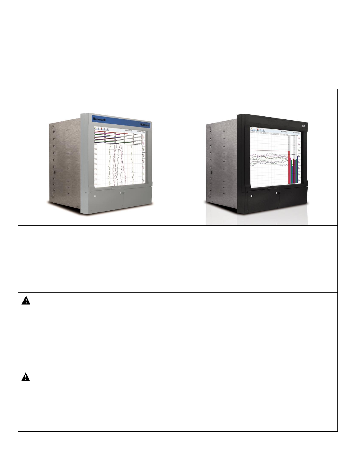
Multitrend GR and SX recorders
Installation Instruction
Transmitter Power Supply Board
Multitrend GR Multitrend SX
This Installation Instruction sheet is intended as a guide for replacing or installing hardware and for setting up
functionality in the recorder. Refer to the User manual for detailed operational requirements.
The Multitrend GR and SX recorders are designed for ease of assembly with minimal disturbance to the rest of the unit.
If unsure, please return the unit to your supplier for repair or upgrade.
Removing the case and opening the back of the recorder should only be performed under the following circumstances:
When an item of hardware requires individual replacement.
When an item of hardware is to be retrospectively fitted.
In all other instances it is recommended that the complete unit be returned to an authorised agent or service centre.
For Agency Approved recorders the product needs to be upgraded or repaired by an Authorized Repair facility
WARNING
HAZARDOUS VOLTAGES
Disconnect all power to the recorder before removing the case and attempting any maintenance procedures.
SAFETY TESTS
Upon completion of service procedures detailed in this manual two basic safety tests should be performed in order to
ensure continued safe operation of the instrument.
Earth Resistance; 25 VDC applied between case and protective earth, bonding resistance should be < 0.1 Ohm.
Insulation Resistance; 500Vdc applied between the earth terminal, and the live and neutral terminal shorted together,
insulation resistance to be >2.0 MOhm. (Mega Ohm, NOT milli Ohm)
Failure to comply with these instructions could result in death or serious injury
CAUTION
OBSERVE ANTI-STATIC PRECAUTIONS
Refer to BS EN61340-5-1: 2001. Basic specification. Protection of electrostatic sensitive devices.
Full anti-static precautions MUST be observed when in contact with the electronics of your recorder.
SAVE DATA, SETUPS AND LAYOUTS
Removal of PCBs and battery back-up will result in the loss of all non-volatile data.
Ensure all data and set-ups are saved.
Failure to comply with these instructions may result in product damage.
43-TV-33-61 iss.4 GLO Jan 21 UK 2
Prerequisite
Before attempting to repair or upgrade a recorder, it is advisable to clear a sufficient work space so components such as
the front panel can be rested on the work surface without getting scratched or damaged.
Panel Mounting
The Transmitter Power Supply Board can be removed, replaced or added to the recorder without removing it from its
mounting panel. If you require the recorder to be removed from the panel, loosen the mounting clamp screws, slide the
clamp towards the rear of the recorder and remove the clamps and the recorder.
Removing the Rear Panel
Removal of the rear panel is necessary for replacement or fitting of the transmitter Power supply card.
To remove the rear panel of the recorder, loosen and remove the two screws (M4 x 8) at the top corners of the rear
panel, taking care to retain both the shake-proof washer and the screw.
Inside the Unit
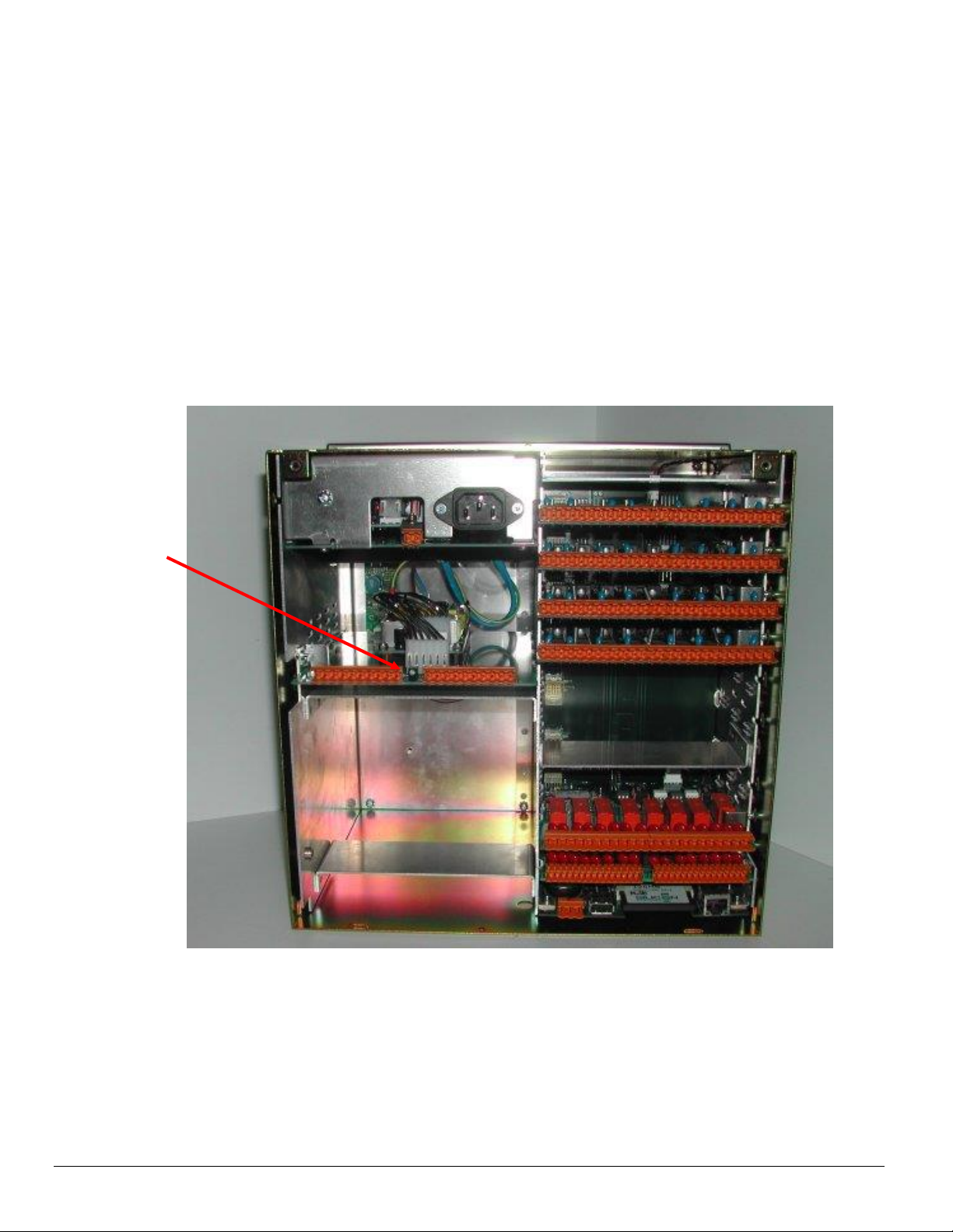
Refer to Figure 1 for the position of the Power Supply Board
Figure 1: Multitrend Transmitter Power Supply board
Transmitter
Power
Supply
Board
43-TV-33-61 iss.4 GLO Jan 21 UK 3
Transmitter Power Supply Boards
This particular option kit is only fitted to the SX Multitrend recorder and GR Multitrend recorder. The board can only be
fitted to a mains powered recorder.
The board supplies 24Vdc at up to 1Amp. The board has an LED that shows the power supply is active when lit.
Connections
All the connections on the 24V connector and the 0V connector are connected together.
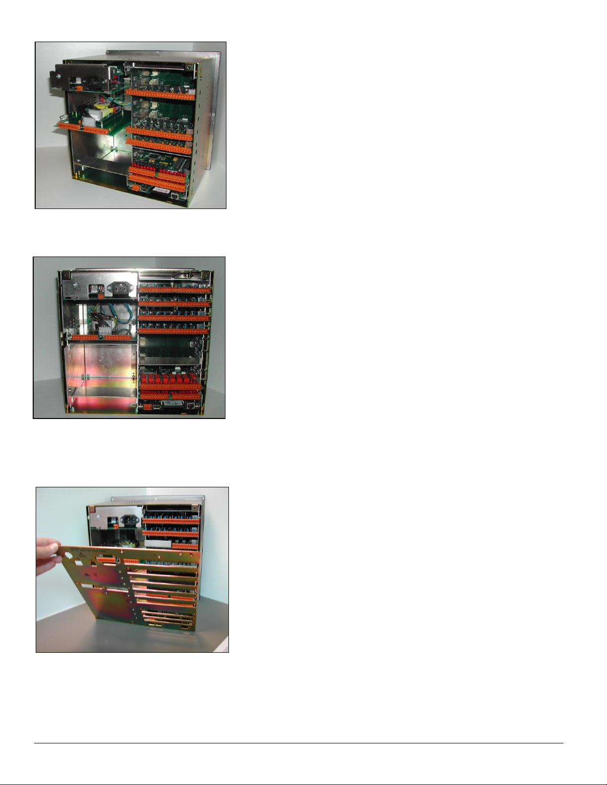
Fitting the Transmitter Power Supply Board
To fit the transmitter power supply board the recorder’s mains power supply board first has to be removed. To remove
the power supply locate and remove the M3 x 8 earth screw from the side of the unit,
Grip the back of the board and gently pull to release the card from its connection to the mother board at the front of the
unit. Remove the card and retain both the screw and the shake-proof washer.
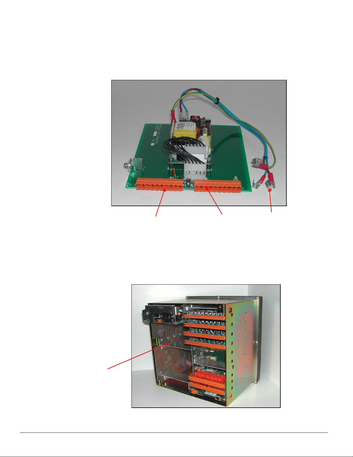
Figure 3 –
TXP board location
Figure 2
Transmitter Power Supply
and lead
24V output
0V output
Loom

43-TV-33-61 iss.4 GLO Jan 21 UK 4
Note which colour wire is connected to which terminal.
Remove the power board and carefully remove the crimp terminals
from the back of the filter as shown.
Connect the lead attached to the transmitter power supply
board to the filter.
The lead should be connected such that the spade terminals for the
bottom two connectors point down, the spade on the top connector
points up. Note position of wire colours
Reconnect the wires removed from the filter, ensuring the wire
colours match and that the crimps are pushed fully home.
Ensure the cables are fitted in the area next to the connector to
ensure they don’t get trapped when board is pushed in.
43-TV-33-61 iss.4 GLO Jan 21 UK 5
Replace both the boards, ensuring they are both in the correct position
using the board guides in the case. Slide the cards carefully back into the
case, until the fixing bracket on the side of the cards is in line with the
fixing holes on the side of the case. Ensure the cards are pushed fully
home.
Replace/fit the M3 x 8 earth screws and shake-proof washers, on the side
of the case, to secure the cards.
Re-assembling the Unit
Remove or add any relevant plastic blanking plates (safety cover) on the
rear panel, by pushing out the push rivets from behind.
To replace the rear panel, angle the rear panel as shown to line up two
location points with the floor of the recorder’s case.
Reposition the shake-proof washers and replace and tighten two screws
(M4 x 8) at the top corners of the rear panel.
If the recorder has been removed from the panel, refit the mounting
clamps to the case in two opposite positions (Nema 4 positions) and
secure into the panel.
Torque setting should be 0.5 - 0.70Nm/4.4 - 6.2lbf-in
Copyrighted Materials. For more information please contact your supplier.
 Loading...