

Page 1
- Low input impedance
- Phase sequence testing
- Dangerous voltage alarm
- 4.5-digit 6000 count LCD resolution
- Peak voltage capture mode
- Hold voltage reading mode
- High accuracy true RMS readings
CAT IV 300V
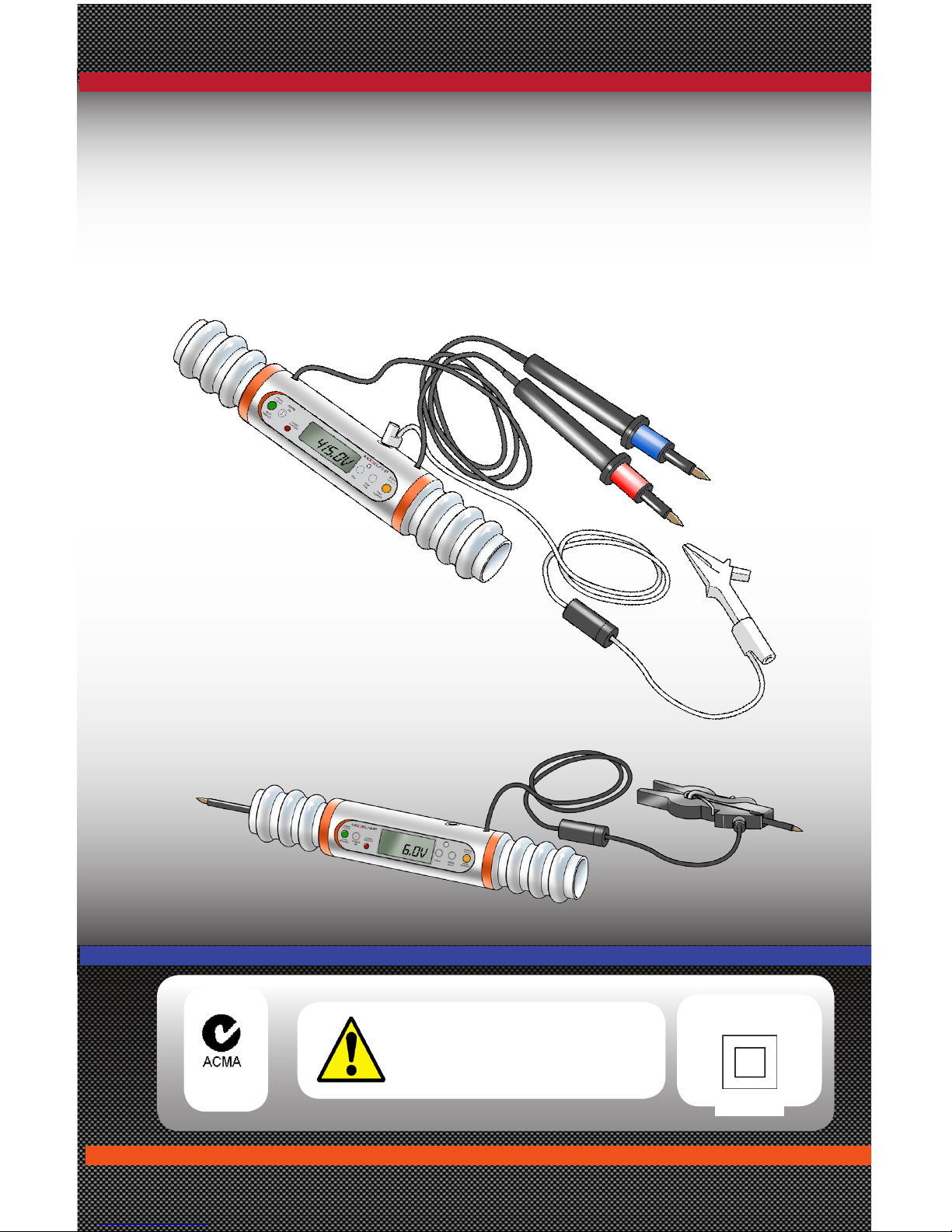
ModieLamp
Digital lamp and phase
Sequence meter
CAUTION
:
Ensure only Phase to
Neutral connection
PENDING
PENDING
Page 2
GL McGavin ModieLamp Manual
Page : 2
SAFETY INFORMATION
• Ensure that user is competent, qualied and authorised to carry
out the required work.
• Avoid working alone.
• Do not use the ModieLamp in wet conditions, or around explosive
gas or vapour.
• Use the ModieLamp only as specied in this manual.
• When using test leads or probes keep your ngers behind the
nger guards.
• Only use leads and probes supplied with the unit.
• Use extreme caution when working around bare conductors or
busbars. Contact with conductors can result in both electric shock
and possible electrocution.
• Use caution with voltages above 30VAC RMS. This voltage poses a
shock hazard.
• Comply with local and national safety requirements when working
in hazardous locations.
• Use only the replacement fuse specied or the protection may be
impaired.
• Always check ModieLamp prior to use.
Safety Information
To ensure safe operation and service of the ModieLamp, please follow these
instructions. Failure to observe warnings can result in severe injury or death.
THE MANUFACTURER DISCLAIMS ALL LIABILITY FOR LOSS
OR DAMAGE SUFFERED AS A RESULT OF:
(A) USE OF THIS UNIT BY UNTRAINED PERSONNEL.
(B) UNAUTHORISED ALTERATION OF THIS UNIT.
(C) USE OF THIS UNIT OTHER THAN SPECIFIED IN
DOCUMENTATION.
Page 3
GL McGavin ModieLamp Manual
Page : 3
Description
The ModieLamp comprises of three sections:
• A test lamp set.
• A specially designed digital voltmeter (DVM), and
• A phase sequence indicator.
Features:
• Low input impedance DVM providing immunity to 'phantom' voltages.
• Phase sequence testing.
• Dangerous voltage alarm, (inception voltage and alarm mark/space ratio can
be factory adjusted to meet customer requirements).
• 4.5-digit 6000 count LCD resolution.
• Advanced electronic chip-set providing high accuracy true RMS readings.
• Peak voltage capture mode.
• Hold voltage reading mode.
• Immune to DC voltage components.
• Multiple lead and probe combinations available. Can be further tailored to
meet customer requirements.
• LCD back-light option.
Intended Use:
• Modielamp’s intended use is as a set of test lamps for low voltage neutral
and phase identication (polarity testing) on three phase (3ø) and single
phase (1ø) systems, overhead lines and underground cables, and for general
electrical installation testing and fault-nding.
• The digital voltmeter (DVM) can test voltage from 0.0VAC to 600.0VAC true
RMS.
• Phase sequence on 415VAC 3ø systems can be identied by connecting a
fused third lead (provided) to the unit.
Page 4
GL McGavin ModieLamp Manual
Page : 4
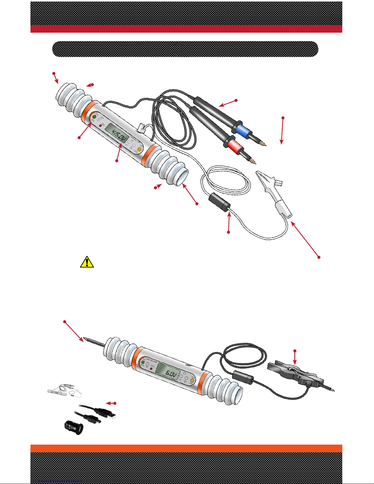
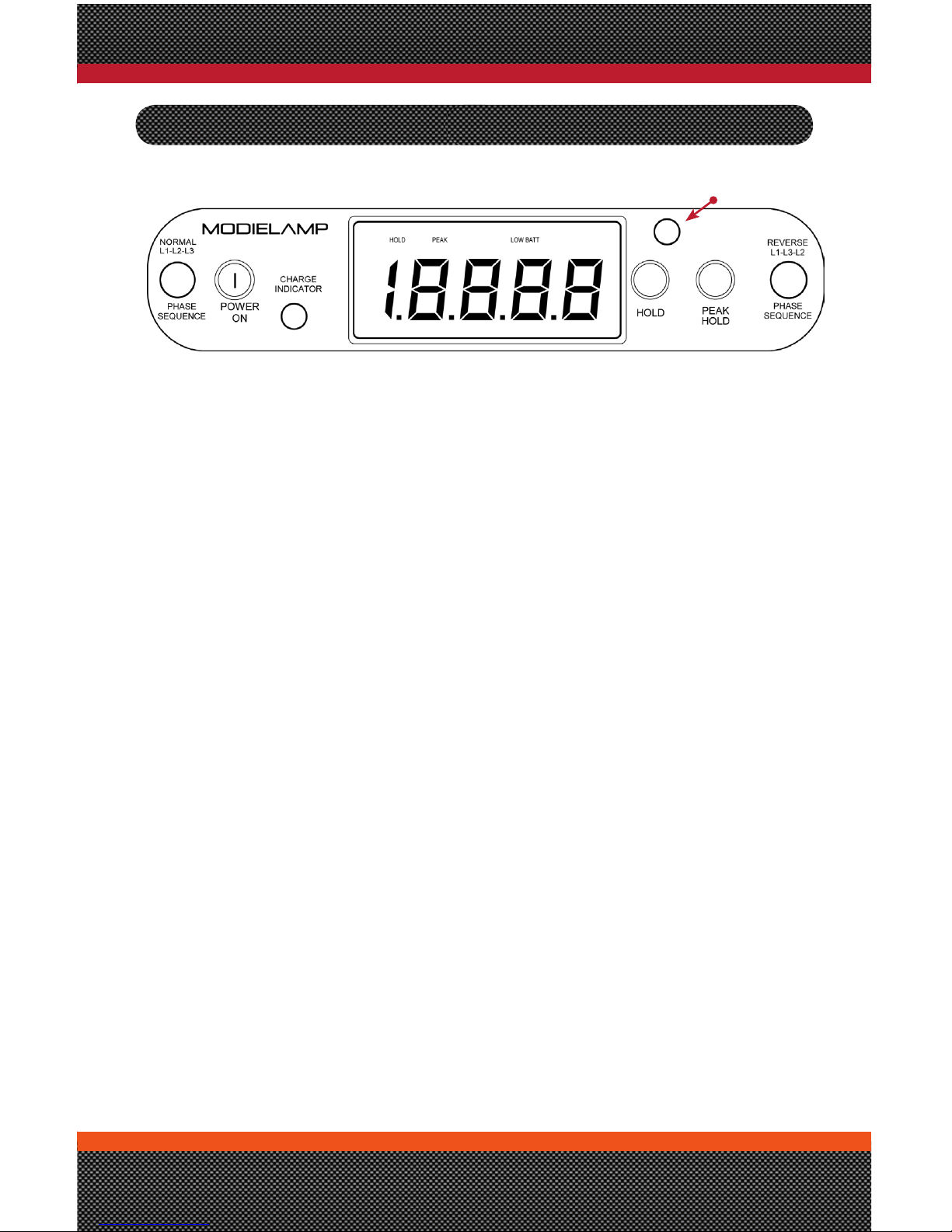
Part identification
Fixed Probe
(Options)
Flat Spike or Round point
Charging Kit (option)
• 240VAC to USB 5VDC
• 12VDC to 5VDC
• USB Lead 700mm Long
Lamp cover
Warning :
Do not open Fuse Cap with power on and leads
connected. Disconnect unit before removing
cap.
LCD
Display
(Option) Peg clip
CAT IV 300V
Flying probes (Fused)
Variable tip congurations
Phase connection Lead
4mm Banana plug with
Alligator Clip CAT IV 300
Inline Fuse holder
Lamp cover
Incandescent
Lamp 25W
Phase Sequence
Indicators
Incandescent
Lamp 25W
Fuse :500mA 500VAC HRC
Very Fast Acting Ceramic fuse
(50kA@AC 500vAC)
SIBA 7012540-0.5
Page 5
GL McGavin ModieLamp Manual
Page : 5
1. Activate the DVM by depressing the POWER ON button. Allow 6 seconds for
unit to self test and calibrate. The unit is ready for testing when the 0.0V
reading is displayed.
2. LOW BATT indicates a battery voltage of less than 2.048VDC. If this is
displayed, the ModieLamp must be recharged using the charger provided, or
via a computer or vehicle USB port.
3. Place the ModieLamp test probes on to the test points.
4. The voltage between the test points will be displayed on the LCD.
5. To enable the test voltage to be temporarily held and displayed following
removal of the test probes from the test point, press HOLD. Pressing HOLD
again returns the unit to its normal metering mode.
6. To enable the peak value of voltage to be captured, press PEAK HOLD. The
maximum value will be constantly displayed and only updated if a higher
value occurs. To deactivate this feature, press PEAK HOLD again.
7. DVM auto switch off occurs after 5 minutes (factory set to user
requirements)
8. Backlight:
• Evaluation model: Backlight automatically switches on when unit
powers up.
• Production model: Backlight will be automatically activated when
ambient light falls below a factory set level via a light sensitive sensor
adjacent to the display. Backlighting can be activated if required
during high ambient lighting levels by covering the light sensitive
sensor opening with a nger or thumb.
Digital voltmeter operation
Light Sensor
Page 6

GL McGavin ModieLamp Manual
Page : 6
GENERAL OPERATING INSTRUCTIONS
Important Note:
Ensure only appropriately trained and qualied personnel use the ModieLamp.
Standard Test-Lamp Usage:
The ModieLamp can be used as a standard set of test-lamps with 480VAC,
415VAC, 240VAC and Load-Glow being readily identiable from the brightness of
the incandescent lamps.
• 480VAC: Full Glow ++ (Rare but occasionally still found in Australia)
• 415VAC: Full Glow (Phase - Phase)
• 240VAC: Half Glow (Phase - Neutral/Earth)
• Load Glow: Ruby Red (Usually apparent when testing across a service
fuse holder with the fuse removed). The supply feeds any connected
load (including the electricity meter voltage coil) via the test lamps.
The level of glow depends on the impedance of the load. The lower the
impedance, the brighter the glow.
General Instructions:
1. Always check the ModieLamp before use.
a. Check leads for any damage to the cables, probes and inline fuse-holder.
b. Check for rm connections between probes, inline fuse-holders and end-
plugs
c. Check for clean and corrosion free test probes.
d. Make sure there are no dangerous cracks or chips.
2. Check the ModieLamp using the Modieprove proving unit.
ModieProve
a. If the ModieProve needs to be tested, there is provided a dummy test
load that can be plugged into the test-points to indicate that the
ModieProve is serviceable.
b. Connect the ModieLamp probes to the ModieProve terminal sockets.
c. If the ModieLamp is serviceable, an LED and a sounder will activate. If
the ModieProve does not activate then the ModieLamp is faulty. It should
be tagged unserviceable and the appropriate authority informed for
repair and replacement.
Page 7

GL McGavin ModieLamp Manual
Page : 7
POLARITY TESTING (GENERAL)
3. The test item connection points should be clean and free from corrosion to
ensure a good contact between the test probe and the test connection point.
4. Use the ModieLamp probes to make contact at the test points.
5. Should the ModieLamp fail to indicate the presence of voltage, it is essential
to test the ModieLamp with the Modieprove proving unit immediately. If the
Modielamp proves serviceable, proceed to next step, otherwise it should be
tagged unserviceable and the appropriate authority informed for repair and
replacement.
6. If upon re-connection to the testing point the unit still does not indicate,
then the test points tested can be considered de-energised.
3ø and 1ø polarity testing can be readily carried out using the ModieLamp.
Most utility companies have their own preferred method of performing the test
depending on location of test and the testing conditions.
In lieu of a preferred company work method, the following procedure can be
adopted to carry out a basic polarity test at a consumer mains switchboard.
Polarity Test of Mains at a Consumer
Switchboard:
1. Turn OFF the main switch/s and any circuit breakers or remove all fuse
carriers.
2. Conrm that bonding conductor to a service support is not connected and
that main neutral is still disconnected from MEN link.
3. Connect supply.
4. Test between the main neutral conductor and the line terminal/s of the main
switch/s. On a multiphase installation, between phases.
a. On a single phase installation the test lamps should light up showing
half-glow, proving that the test lamps are in order and that the required
supply is available.
b. On a three phase installation the test lamps should light up showing full
glow between any two phases and half glow between any phase and
neutral.
5. Test between the main neutral conductor and an independent earth
electrode. The test lamps should not light.
6. Test between an independent earth electrode and the line terminal/s of
main switch/s. The test lamps should light.
Page 8

GL McGavin ModieLamp Manual
Page : 8
NOTE: Failure of the test lamps to light during this test indicates
that the resistance between the independent electrode and the
general mass of earth is too high. If this is the case (and a better
earth cannot be established), disconnect the ModieLamp from the
testing points, unscrew and remove one of the lamps from the lamp
socket, and re-attach the ModieLamp to the test points. The digital
voltmeter (DVM) will now measure the Line to Earth voltage. This
should be equal to the nominal Phase-Neutral voltage.
7. Test between the main neutral conductor and both line and load side of all
circuit protective devices. The test lamps should not light, proving there
is no supply at the circuit protective devices with the main switch/s in the
"OFF" position.
8. Replace the main neutral conductor and main earthing conductor into the
neutral link.
9. Turn the main switch ON.
NOTE: A similar polarity test sequence is required for sub-mains.
NOTE: Replacement of the main earth and neutral into the neutral
link at this time is to minimise the possibility of a potential rise
on the earthing system during tests and causing others on site to
receive a shock.
10. Test between the main neutral conductor and the line side of all circuit
protective devices (CPD's) – proves supply at CPD's (half glow).
11. Test between the phases of circuit protective devices (line side) on a
multiphase installation (full glow).
12. Test between the main neutral conductor and the load side of any circuit
breakers. Test lamps should not light proving the CBs turn off (no-glow).
13. Turn on all CBs and test the load side of all CBs. Lamps should light proving
CBs turn on (half glow).
14. Reinstate any service bonding conductor that was removed.
Page 9

GL McGavin ModieLamp Manual
Page : 9
1. Connect the ModieLamp to any 2 phases. Ensure that both the green and
orange phase rotation indicator neon lamps light up.
2. Connect lead provided to 4mm socket labelled L2. Connect all 3 connections
in the appropriate sequence, e.g.. L1 to Aø (Red phase)ø, L2 to Bø (White
phase), L3 to Cø (Blue phase).
A Green indication shows normal (correct) phase sequence.
An Orange indication shows reversed (incorrect) phase sequence
Using the ModieLamp for Continuity Testing:
If a purpose built continuity tester is not readily available, the ModieLamp
together with the ModieProve can be used together as a Continuity Tester by
connecting them in series as shown. If continuity is established, the ModieProve
LED and audible alarm will activate.
MODIEPROVE
MODIELAMP
DE-ENERGISED
CIRCUIT UNDER TEST
Phase sequence testing
Continuity testing
NORMAL (CORRECT) PHASE SEQUENCE
L1-L2-L3
REVERSED (INCORRECT) PHASE SEQUENCE
L1-L3-L2
Page 10

GL McGavin ModieLamp Manual
Page : 10
USER MAINTENANCE
The only user maintenance permitted by the manufacturer is cleaning the
ModieLamp outer shell and the replacement of the fuse and lamps with the
recommended types.
Any other maintenance performed will invalidate the warranty.
Lamp Replacement:
Lamp type: 25W 240VAC E14 Edison screw
1. Using a small at blade screw driver undo
locking screw (keep safe).
2. Unscrew lamp cover anti-clockwise.
3. Unscrew lamp.
4. Replace lamp.
5. Replace light cover Match screw hole
positions.
6. Replace screw.
Fuse Replacement
Fuse type: SIBA7012540-0.5, 6.3x32
Very Quick-Acting 500VAC, 500mA or similar.
Flying probe Probe:
1. Unscrew handle anticlockwise.
2. Remove fuse.
3. Replace with new fuse.
4. Screw handle back together
rmly.
CAUTION :
• Disconnect all Cables from any source before removing lamp cover.
• If lamp is broken use caution when removing lamp base.
CAUTION :
• Disconnect all Cables from any source before unscrewing cover.
• Do not replace with incorrect fuse type. Always contact the
manufacturer if in doubt.
Page 11

GL McGavin ModieLamp Manual
Page : 11
Inline Fuse carrier:
1. Using at blade screw driver undo locking screw (keep safe).
2. Unscrew two halves.
3. Remove fuse from
holding clips.
4. Place new fuse in
fuse clips.
5. Screw back together
6. Replace locking
screw.
Charging Unit
1. When the LCD display indicated LOW BATT, the unit has approximately 30
minutes battery life remaining. Recharge is recommended.
2. To charge Battery.
1. Remove sealing plug from charge socket.
2. Plug USB mini plug into charge socket.
3. Attach USB plug to any USB 5VDC 500mA supply.
• USB port on computer (Laptop).
• 240VAC to 5VDC power adaptor (optional).
• 12VDC to 5VDC car adaptor (optional).
4. A RED charge light will indicate unit is charging (unit will automatically
turn off).
3. When ModieLamp fully charged, the RED charge light will turn off.
4. Remove lead and replace sealing plug.
Cleaning:
Clean unit with damp cloth. May use house hold surface spray on cloth,(do not
direct spray).
Do not Submerge in any liquid.
Page 12

GL McGavin ModieLamp Manual
Page : 12
supPlement
Instructions for using the ModieLamp
referencing AS4741: 2010
SECTION 4 TESTING PROCEDURES
PART 4.2 ACCEPTABLE NEUTRAL VOLTAGE CRITERIA
ModieLamp can be used to measure the voltage between the Neutral conductor
and an independent Earth, following removal of the customer multiple earthed
neutral (MEN) link. The acceptance criterion according to this Australian
Standard stipulates Neutral voltage levels of 6V, 15V and 32V in Sect: 4.2. The
ModieLamp resolution and accuracy for these voltage measurements are as
quoted.
PART 4.3 POLARITY TEST
Can be performed as shown in Figure A1 of the standard .
Note: If the authority or user has a concern regarding the livening
up of an installation's earthing system as a result of the low
internal impedance of the test lamps combined with high earth
resistance, the user may remove one lamp from the ModieLamp and
use it as a digital voltmeter. The procedure is then identical, except
instead of half-glow and no-glow, the user will be looking for a
nominal 240VAC (or 230VAC) and 0VAC.
PART 4.4 NEUTRAL INTEGRITY TEST
1. Neutral Integrity Test Procedure according to AS4741 APPENDIX B: B2
VOLTAGE METHOD:
a. Remove customer MEN link
b. Connect a suitable test load to the supply between Phase and Neutral
conductors.
c. Measure the Neutral Conductor Voltage with respect to an Independent
Earth conductor. Note this value. Assess its value with respect to the
voltage level criteria given in AS4741 Sect: 4.2.
(*IMPORTANT NOTE: In high resistivity soils such as sand or gravel, or
in rocky areas, the user should remove one lamp in order to facilitate a
high input impedance digital voltmeter reading.)
d. On completion of test, replace the MEN link securely.
e. Leave work area tidy and safe.
2. Neutral Integrity Test Procedure according to AS4741 APPENDIX B: B3 LOOP
Page 13

GL McGavin ModieLamp Manual
Page : 13
Chart 1: Neutral and Loop Impedance Values
Instructions: Find value of measured
Neutral-Earth Voltage on horizontal
scale of chart. Find the Neutral
Impedance Zn on the left vertical axis.
The Loop Impedance can be found
on the right vertical axis under the
conditions stated.
* Only valid if Zp=Zn
where:
Zp=Phase Line Impedance
and
Zn=Return Path Impedance
IMPEDANCE METHOD:
Using a ModieLoad unit (available together with, or as a separate item to,
the ModieLamp) as a suitable test load between incoming Phase and Neutral
conductors following the methodology as for (1) above, the user can obtain
an accurate measure of Neutral Impedance by using Chart 1 or Table 1. Loop
Impedance can be obtained under the conditions stated.
Vn [Volts] Zn [Ohms] Zloop*[Ohms]
0 0.00 0.00
1 0.10 0.20
2 0.20 0.41
3 0.31 0.61
4 0.41 0.82
5 0.51 1.02
6 0.61 1.22
7 0.71 1.43
8 0.82 1.63
9 0.92 1.84
10 1.02 2.04
1 1.12 2.24
12 1.22 2.45
13 1.33 2.65
14 1.43 2.86
15 1.53 3.06
Page 14

GL McGavin ModieLamp Manual
Page : 14
TECHNICAL SPECIFICATIONS
Test voltage range: 0.0VAC - 600.0VAC @ 50Hz
Input impedance: 600Ω nominal (Lamps OFF), 7kΩ nominal
(Lamps ON), 640kΩ (Lamp/s removed)
Resolution: 4.5 digits (6000 count)
Accuracy: +/- (1% +1) Least Signicant Digit
Crest factor (CF) error: <0.5% for 1<CF<10
Auto switch off range: Factory set 3min to 30min (user Dened)
Audible alarm inception voltage: (Can be
tailored to meet customer requirements)
Factory Set at 32VAC
Audible alarm mark-space ratio: 80db @ 10cm (1sec ON 5sec OFF)
Data conversion rate: 5Hz
LCD update rate: 2.5Hz
Current at 240VAC: 70 mA (100mA @ 415)
Phase sequence indication parameters: 415VAC @50Hz
Lamps: 2 x 25W 240VAC E14 Edison screw
Operating temperature range: 0ºC - 70ºC
Designed to (environmental conditions):
AS61010 -1 2003 (Awaiting Approval)
IP rating: IP56 (awaiting approval)
Certied safety rating: AS61010 CAT IV 300V (awaiting approval)
PART 4.5 PHASE ROTATION TEST
Phase sequence should be recorded prior to disconnection. Re-connection should
be in accordance with the previously recorded direction of phase rotation.
Modielamp kit a
1 * Modielamp (Any Model)
1* ModieProve (Lamp Tester)
• 1 * Prove test
1 * Recharge Kit
• USB lead (700mm Long)
• 240VAC to USB 5VDC Adaptor
• 12DC to USB 5VDC Car Adaptor
1 * ABS Hard case foam lled
Testing Awaiting approval for AS61010-1 2003, AS/NZS 60529 &
AS/NZS 61000-6-3 from Austest Lab Reference Number GLM130731
Page 15

GL McGavin ModieLamp Manual
Page : 15
Equipment maintenance
This product has been manufactured in Australia by:
Please contact the manufacturers for all repairs, calibrations, spare parts and
technical advice.
Do not replace with incorrect fuse type. Consult manufacturers if in doubt.
Fuse type(user replaceable):
SIBA7012540-0.5, 6.3x32 Very Quick-acting 500V, 500mA or similar.
GL McGAVIN PTY. LTD.
ABN 73 383 170 955
MANUFACTURERS OF ELECTRICAL TESTING
AND MEASUREMENT
Delivery Address: 43-45 Orlando Road
Lambton NSW 2299
Australia
Postal Address: P.O. Box 83
Lambton NSW 2299
Australia
Phone: 02 4952 6304
Phone Int: +61 2 4952 6304
Fax: 02 4956 1054
Fax Int: +61 2 4956 1054
Email: sales@dn.eng.com.au
Web: www.glmcgavin.com.au
CAUTION :
Do not open Fuse Cap with power on and leads connected. Deactivate Unit as
per procedure before removing cap.
Cleaning:
Clean Unit With damp Cloth. May use House hold surface spray on Cloth,(do not
direct spray).
Do not Submerge in any liquid.
Australian Made
Page 16

ModieLamp Manual version 4 20130814
© Copyright 2013 GL McGavin Pty. Ltd.
Delivery Address:-
43-45 Orlando Road
Lambton NSW 2299
Australia
Postal Address:-
P.O. Box 83
Lambton NSW 2299
Australia
Phone: 02 4952 6304
Phone Int: +61 2 4952 6304
Fax: 02 4956 1054
Fax Int: +61 2 4956 1054
Email: sales@dn.eng.com.au
Web: www.glmcgavin.com.au
GL Mcgavin pty. Ltd.
ABN 73 383 170 955
Quality
ISO 9001
QEC29835
 Loading...