

GLI International PRO-E3 Operating Manual

OPERATING MANUAL
PRO-series Model E3
Electrodeless Conductivity
Transmitter
(for conductivity, % concentration, and TDS measurement)
Worldwide Headquarters and Sales:
GLI International, Inc.
9020 West Dean Road
Milwaukee, Wisconsin 53224
U.S.A.
In the interest of improving and updating its equipment, GLI reserves the right to alter specifications to equipment at any time.
Rev. 0-201 PRO-series Model E3 Electrodeless Conductivity Transmitter
Phone:
Fax:
E-mail:
Web:
Represented By:
[414] 355-3601
[414] 355-8346
info@gliint.com
www.gliint.com
Viridor Instrumentation
A company
1
This operating manual and other GLI operating manuals
are available on GLI’s web site at gliint.com. when viewed
using Adobe’s free Acrobat reader. To get this reader, link
to Adobe through GLI’s web site or visit Adobe’s web site
at adobe.com.
PRO-series Model E3 Electrodeless Conductivity Transmitter Rev. 0-201
2

IMPORTANT SAFETY INFORMATION
This transmitter is compliant with safety standards as outlined in:
FMRC Class Numbers 3600, 3611, and 3810 (U.S.A.)
CSA C22.2 No. 142 and C22.2 No. 213 (Canada)
EN 61010-1 (European Community)
Please read and observe the following:
•
The transmitter (not intrinsically safe) must always be located in a safe (non-hazardous) area.
•
Since the transmitter is powered by only low DC voltage, it is completely safe to handle.
•
Wiring or repairs should only be performed by qualified personnel, and only when transmitter is unpowered.
•
Whenever it appears that transmitter safety is questionable, disable the transmitter to ensure against
any unintended operation. For example, an unsafe condition is likely when:
1) The transmitter appears visibly damaged.
2) The transmitter fails to operate properly or provide the intended measurements.
3) The transmitter has been stored for long periods at temperatures above 158°F (70°C).
•
Install this transmitter in accordance with relevant local codes and instructions contained in this oper-
ating manual. Also, note and comply with the transmitter’s technical specifications and ratings.
HELPFUL IDENTIFIERS
In addition to information on installation and operation, this instruction manual may contain
WARNINGS pertaining to user safety, CAUTIONS regarding possible instrument malfunction,
and NOTES on important, useful operating guidelines.
WARNING:
A WARNING LOOKS LIKE THIS. IT WARNS YOU OF THE
POTENTIAL FOR PERSONAL INJURY.
CAUTION:
A CAUTION LOOKS LIKE THIS. IT ALERTS YOU TO POSSIBLE
INSTRUMENT MALFUNCTION OR DAMAGE.
☞
NOTE: A note looks like this. It alerts you to important operating
information.
Rev. 0-201 PRO-series Model E3 Electrodeless Conductivity Transmitter
3

WARRANTY
GLI International, Inc. warrants the PRO-series Model E3 to be free from defects
in material or workmanship for a period of 2 years (24 months) from the date of
shipment of this product from our facility. A warranty claim will not be honored if
defects are not reported within the warranty period, or if GLI International determines that defects or damages are due to normal wear, misapplication, lack of
maintenance, abuse, improper installation, alteration, or abnormal conditions.
GLI International’s obligation under this warranty shall be limited to, at its option,
replacement or repair of this product. The product must be returned to GLI International, freight prepaid, for examination. The product must be thoroughly
cleaned and any process chemicals removed before it will be accepted for replacement or repair. GLI International’s liability shall not exceed the cost of the
product. Under no circumstances will GLI International be liable for any incidental or consequential damages, whether to person or property. GLI International
will not be liable for any other loss, damage or expense of any kind, including
loss of profits, resulting from the installation, use, or inability to use this product.
PRO-series Model E3 Electrodeless Conductivity Transmitter Rev. 0-201
4
CONDENSED OPERATING INSTRUCTIONS
This manual contains details for all operating aspects of the instrument. The following condensed instructions are provided to assist you in getting the instrument started up and operating as quickly as
possible.
tion.
These condensed instructions only pertain to basic conductivity measurement
To measure % concentration or TDS, or to use specific features of the instrument, refer to the
appropriate sections in this manual for instructions.
A. CONNECTING SENSOR/CONFIGURING TEMPERATURE ELEMENT TYPE
1. After properly mounting the transmitter (PART TWO, Section 2), connect the GLI electrodeless
conductivity sensor, matching wire colors to terminals as indicated:
Sensor Wire Colors Connect To TB2
White Terminal 1
Blue Terminal 2
Inner and Outer Shield Wires Terminal 3
Red Terminal 4
Yellow Terminal 5
No connection (not used) Terminal 6
Green Terminal 7
2. The transmitter is supplied factory-set for automatic temperature compensation using the Pt
1000 ohm temperature element built into GLI electrodeless conductivity sensors. For fixed
MANUAL temperature compensation, you must change the temperature element type (see
PART THREE, Section 3.2, subheading “Select TEMP ELEMENT Type”).
opera-
B. CONNECTING DC POWER
Refer to PART TWO, Section 3.2, 3.3, 3.4 or 3.5 to connect DC power to the transmitter.
C. CALIBRATING THE TRANSMITTER
The transmitter must be calibrated so that measured values will correspond to actual process values.
Preferably, use the “COND CAL” calibration method to enter the known value of a properly prepared
conductivity reference solution. (When using a sample of the process to calibrate, use the “SAMPLE
CAL” method to enter its known value determined by laboratory analysis or a comparison reading.)
Calibration Tip!
Each electrodeless conductivity sensor has a unique zero point and span. Consequently, when calibrating a sensor for the first time, always zero it according to step 1. Zeroing
provides the best possible measuring accuracy.
NOTE: An in-progress calibration can always be aborted by pressing the ESC key. After the
“ABORT: YES?” screen appears, do one of the following:
•
Press ENTER key to abort. After the “CONFIRM ACTIVE?” screen appears, press ENTER key
again to return the analog output to its active state (MEASURE screen appears).
•
Use
×
or
Ø
key to choose “ABORT: NO?” screen, and press ENTER key to continue calibration.
×
Ø
1. Zero the sensor if it is being calibrated for the first time. If not, disregard this step and perform
steps 2 through 13.
Zeroing Tip!
press
ENTER key
If at any time during zeroing, the “ZERO: CONFIRM FAILURE?” screen appears,
×
to confirm. Then, use the
×
or
Ø
to select between “CAL: EXIT” or
key
Ø
“CAL: REPEAT” and do one of the following:
Rev. 0-201 PRO-series Model E3 Electrodeless Conductivity Transmitter
(continued on next page)
5
CONDENSED OPERATING INSTRUCTIONS
C. CALIBRATING THE TRANSMITTER -- (continued)
•
With the “ZERO? (CAL: EXIT)” screen selected, press
CONFIRM ACTIVE?” screen appears, press
its active state (MEASURE screen appears).
•
With the “ZERO? (CAL: REPEAT)” screen selected, press
A. Make sure that the sensor is dry before zeroing.
B. Press
C. Press
D. Press
E. Press
F. Press
G. With the dry sensor
H. After the “ZERO: CONFIRM ZERO OK” screen appears, press
MENU key
showing, use
ENTER key
ENTER key
Ø
key
Ø
ENTER key
zeroing, the analog output is automatically “held” at the last measured value.)
to display a “MAIN MENU” screen. If the screen is not
×
Ø
or
×
twice to display
key
Ø
to display it.
to display
again to display
to display the “ZERO: IN DRY AIR?” screen.
held in air, press
ENTER key
.
.
ENTER key
again to start automatic zeroing. (During
ENTER key
again to return the analog output to
ENTER key
.
ENTER key
. After the “ZERO:
to repeat zeroing.
to end zeroing.
I. After the “ZERO: CONFIRM ACTIVE?” screen appears, press
analog output to its active state (MEASURE screen appears).
2. Prepare a reference solution that has a conductivity value within the measuring range that you
set for the transmitter. For best accuracy, the conductivity reference solution value should be
near the typical measured process value. In PART THREE, Section 4.3, subsection “COND CAL
Method,” refer to step 1 and Table E for solution preparation details.
3. Thoroughly rinse the clean sensor in de-ionized water. Then immerse the sensor in the prepared
reference solution.
pending on their temperature differences, this may take up to 30 minutes.
Important: Allow the sensor and solution temperatures to equalize.
ENTER key
to return the
De-
NOTE: Suspend the sensor to prevent it from touching the container. Simply laying it into the
container will produce calibration error.
Calibration Tip!
screen appears, press
“CAL: EXIT” or “CAL: REPEAT” and do one of the following:
•
With the “COND? (CAL: EXIT)” screen selected, press
CAL: CONFIRM ACTIVE?” screen appears, press
to its active state (MEASURE screen appears).
•
With the “COND? (CAL: REPEAT)” screen selected, press
of the point.
If at any time during calibration, the “COND CAL: CONFIRM FAILURE?”
×
ENTER key
(continued on next page)
to confirm. Then, use the
ENTER key
ENTER key
ENTER key
Ø
or
×
key
Ø
to select between
. Then, after the “COND
to return the analog output
to repeat calibration
PRO-series Model E3 Electrodeless Conductivity Transmitter Rev. 0-201
6
CONDENSED OPERATING INSTRUCTIONS
C. CALIBRATING THE TRANSMITTER -- (continued)
4. Press
5. Press
6. Press
7. Press
MENU key
ENTER key
ENTER key
ENTER key
temperature to match the desired reference temperature, if other than 25°C, and press
key
to enter the value.
to display
to display
again to display
again to display
.
.
.
arrow keys
. Use
to adjust the displayed
NOTE: During calibration, the analog output is automatically “held” at the last measured value.
8. After the screen appears, use
value to match the known slope of the reference solution, and press
arrow keys
to adjust the displayed % per °C
ENTER key
to enter value.
NOTE: Measured values are normally compensated using the configured temperature compen-
sation method. While using the “COND CAL” method to calibrate, the measured
reference solution is linearly compensated by these entered reference temperature and
slope values.
9. With the sensor in solution and the screen displayed, press
confirm. This active
tion value.
screen appears showing the measured reference solu-
ENTER key
ENTER
to
10. Wait for the reading to stabilize which may take up to 30 minutes. Then press
“PLEASE WAIT” screen may appear if the reading is still too unstable. After the reading has sta-
bilized, this static
11. Use the
ence solution, and press
CAL OK?” screen appears).
12. Re-install the sensor into the process.
13. Press
put status screen. When the reading corresponds to the actual typical process value, press
ENTER key
This completes “COND CAL” calibration. The transmitter is now ready to measure conductivity.
arrow keys
ENTER key
again to return the analog output to its active state (MEASURE screen appears).
to adjust the displayed value to exactly match the known value of the refer-
ENTER key
to display the active measurement reading on the “CONFIRM ACTIVE?” out-
screen appears showing the “last-measured” value.
to enter the value and complete calibration (“CONFIRM
ENTER key
NOTE: To change MEASURE screen display format, for example from 0-2000 µS/cm to 0-2.000
mS/cm, refer to PART THREE, Section 3.2, subheading “Select DISPLAY FORMAT.”
D. COMPLETING TRANSMITTER CONFIGURATION
To further configure the transmitter to your application requirements, use the appropriate
CONFIGURE screens to make selections and “key in” values. Refer to PART THREE, Section 3 for
complete configuration details.
. The
Rev. 0-201 PRO-series Model E3 Electrodeless Conductivity Transmitter
7

PRO-series Model E3 Electrodeless Conductivity Transmitter Rev. 0-201
8
TABLE OF CONTENTS
PART ONE - INTRODUCTION
SECTION 1 GENERAL INFORMATION
1.1 Capability Highlights ........................................................................13-14
1.2 Transmitter Safety .................................................................................14
1.3 Retained Configuration Values .............................................................14
1.4 Transmitter Serial Number ....................................................................14
1.5 EMI/RFI Conformance...........................................................................14
SECTION 2 SPECIFICATIONS
....................................................................................15-16
PART TWO - INSTALLATION
SECTION 1 UNPACKING
SECTION 2 MECHANICAL REQUIREMENTS
2.1 Location................................................................................................. 17
2.2 Wall and Pipe Mounting ........................................................................18
2.3 Panel Mounting .....................................................................................19
2.4 Integral Sensor Mounting ...................................................................... 20
SECTION 3 ELECTRICAL CONNECTIONS
3.1 GLI Electrodeless Conductivity Sensor ............................................21-22
3.2 Two-wire Hookup ..................................................................................23
3.3 Three-wire Hookups (load sinking or load sourcing
with or without RS-485 serial communication) .............................23-25
3.4 Four-wire Hookups (with or without RS-485
serial communication) ..................................................................25-26
3.5 Monitor Mode Hookups (without current loop and
with or without RS-485 serial communication) ..................................27
.................................................................................................17
PART THREE - OPERATION
SECTION 1 USER INTERFACE
1.1 Display .................................................................................................. 28
1.2 Keypad .............................................................................................28-29
1.3 MEASURE Screen (normal display mode) ............................................30
SECTION 2 MENU STRUCTURE
2.1 Displaying Main Branch Selection Screens ..........................................31
2.2 Displaying Top-level Menu Screens...................................................... 32
2.3 Displaying Submenu Screens ...............................................................33
2.4 Adjusting Edit/Selection Screen Values ................................................33
2.5 Entering (Storing) Edit/Selection Screen Values/Choices..................... 33
Rev. 0-201 PRO-series Model E3 Electrodeless Conductivity Transmitter
9

TABLE OF CONTENTS (continued)
SECTION 3 TRANSMITTER CONFIGURATION
3.1 Selecting LANGUAGE to Operate Transmitter......................................34
3.2 Configuring Sensor Characteristics:
SELECT MEASURE (conductivity, concentration or TDS) .........34-35
Select DISPLAY FORMAT..........................................................35-36
Select Temperature COMPENSATION.......................................36-37
CONFIG CONC or CONFIG TDS Measurement
(not needed for conductivity) .................................................37-41
CONFIG LINEAR or CONFIG T-TABLE Temp. Comp. (con-
figuration not needed for other compensation methods) .......42-45
SET FILTER Time............................................................................ 45
ENTER NOTE (top line of MEASURE screen) ..............................45-46
Select TEMP ELEMENT Type ....................................................46-47
SET T FACTOR (sensor’s GLI-certified “T” factor) .....................47-48
3.3 SET °C OR °F (temperature display format) ......................................... 48
3.4 Configuring Analog Output:
SET PARAMETER (representation) ................................................ 49
SET 4 mA and 20 mA VALUES (range expand) .........................49-50
SET FILTER Time............................................................................ 50
SET FAIL LEVEL Mode (off, 4 mA or 20 mA) ..................................50
3.5 SET PASSCODE (feature enabled or disabled) ................................... 51
3.6 Configuration Setting Summary (ranges/choices and defaults) .......52-53
SECTION 4 TRANSMITTER CALIBRATION
4.1 Important Information .......................................................................54-55
4.2 ZERO Procedure (first-time sensor calibration only)........................55-56
4.3 Conductivity Calibration:
COND CAL Method.....................................................................56-58
SAMPLE CAL Method.................................................................59-60
4.4 % Concentration Calibration:
CONC CAL Method.....................................................................60-62
COND CAL Method..........................................................................62
4.5 TDS Calibration................................................................................62-64
4.6 Analog Output Calibration ................................................................64-65
SECTION 5 TEST/MAINTENANCE
5.1 STATUS Checking (transmitter and sensor) ....................................66-67
5.2 HOLD OUTPUT.....................................................................................67
5.3 OUTPUT Test Signal........................................................................67-68
5.4 Firmware (EPROM VERSION) Checking ..............................................68
5.5 SELECT SIM Measurement .............................................................68-69
5.6 SIM SENSOR Setting............................................................................69
5.7 RESET CONFIGURE Values to Factory Defaults............................69-70
5.8 RESET CALIBRATE Values to Factory Defaults ..................................70
PRO-series Model E3 Electrodeless Conductivity Transmitter Rev. 0-201
10

TABLE OF CONTENTS (continued)
PART FOUR - SERVICE AND MAINTENANCE
SECTION 1 GENERAL INFORMATION
...........................................................................71
SECTION 2 PRESERVING MEASUREMENT ACCURACY
2.1 Keeping Sensor Clean ..........................................................................71
2.2 Keeping Transmitter Calibrated ............................................................71
2.3 Avoiding Electrical Interference............................................................. 71
SECTION 3 TROUBLESHOOTING
3.1 Checking Electrical Connections........................................................... 72
3.2 Verifying Sensor Operation ...................................................................72
3.3 Verifying Transmitter Operation ............................................................72
3.4 Verifying Sensor Interconnect Cable Integrity....................................... 72
SECTION 4 TRANSMITTER REPAIR/RETURN
4.1 Customer Assistance.............................................................................73
4.2 Repair/Return Policy .............................................................................73
Rev. 0-201 PRO-series Model E3 Electrodeless Conductivity Transmitter
11

TABLE OF CONTENTS (continued)
ILLUSTRATIONS
Figure 1-1
Figure 2-1
Figure 2-2
Figure 2-3
Figure 2-4
Figure 2-5
Figure 2-6
Figure 2-7
Figure 2-8
Figure 2-9
Figure 2-10
Figure 2-11
Figure 2-12
Figure 2-13
Figure 2-14
EMI/RFI Immunity Diagram ............................................................................................. 14
Wall and Pipe Mounting Details....................................................................................... 18
Panel Mounting Details.................................................................................................... 19
Integral Sensor Mounting Details ..................................................................................... 20
Transmitter Terminal Designations .................................................................................. 21
Connecting GLI Electrodeless Conductivity Sensor ......................................................... 22
Two-wire Hookup............................................................................................................. 23
Three-wire Hookup -- Load Sinking.................................................................................. 24
Three-wire Hookup -- Load Sinking with RS-485 Serial Communication .......................... 24
Three-wire Hookup -- Load Sourcing ............................................................................... 25
Three-wire Hookup -- Load Sourcing with RS-485 Serial Communication ........................ 25
Four-wire Hookup without RS-485 Serial Communication ................................................ 26
Four-wire Hookup with RS-485 Serial Communication..................................................... 26
Monitor Mode Hookup (without Current Loop) -- without RS-485 Serial Communication .. 27
Monitor Mode Hookup (without Current Loop) -- with RS-485 Serial Communication ....... 27
Figure 3-1
Table A
Table B
Table C
Table D
Table E
Transmitter Keypad ......................................................................................................... 29
TABLES
BUILT-IN Chemical Concentration Tables ....................................................................... 38
Values for USER-DEFINED Concentration Table ............................................................ 39
Values for TEMP TABLE ................................................................................................. 44
Transmitter Configuration Settings (Ranges/Choices and Defaults) ............................ 52-53
Conductivity Reference Solutions.................................................................................... 57
PRO-series Model E3 Electrodeless Conductivity Transmitter Rev. 0-201
12
PART ONE - INTRODUCTION SECTION 1 - GENERAL INFORMATION
PART ONE - INTRODUCTION
ECTION
1.1 Capability Highlights
Sensor Input
S
GENERAL INFORMATION
The transmitter can be used with any GLI Model 3700E-series
electrodeless conductivity sensor. These sensors have a builtin Pt 1000 RTD temperature compensator element.
1
MEASURE Screen
Passcode-protected
Access
Calibration Methods
The MEASURE screen (normal display mode) can provide
different readouts of measured data. With the MEASURE
ÕÕ or
screen displayed, press
•
Measured conductivity, % concentration or TDS
•
Measured temperature (°C or °F)
•
Measured conductivity, % concentration or TDS and temperature
•
Measured analog output value (mA)
•
Measured uncompensated conductivity v alue corresponding to
concentration readout (only available when transmitter is set up
to measure concentration)
ÖÖ key to show:
For security, you can enable a passcode feature to restrict access to configuration and calibration settings to authorized
personnel only. See PART THREE, Section 3.5 for details.
Each sensor has a unique zero point and span. Therefore,
always ZERO the sensor in air if it is being calibrated for the
first time (PART THREE, Section 4.2). Specific methods to
calibrate for sensor span are available and dependent on
the transmitter’s configured measurement (conductivity, %
concentration or TDS). For calibration details, refer to Section 4.3, 4.4 or 4.5 respectively. The analog output loop can
also be calibrated (Section 4.6).
Analog Output
Rev. 0-201 PRO-series Model E3 Electrodeless Conductivity Transmitter
The transmitter’s isolated 4-20 mA analog output can be
assigned to represent one of these measurements:
•
Measured conductivity, % concentration or TDS
•
Measured temperature
Parameter values can be entered to define the endpoints at
which the 4 mA and 20 mA analog output values are desired (range expand). For output setup details, see PART
13
PART ONE - INTRODUCTION SECTION 1 - GENERAL INFORMATION
THREE, Section 3.4.
1.2 Transmitter Safety
1.3 Retained
Configuration Values
1.4 Transmitter
Serial Number
☞
NOTE: During calibration, the analog output is automati-
cally held at the last measured value and, upon
completion, returned to its active state.
The transmitter is completely safe to handle. Only low DC
voltage is present.
WARNING:
ALWAYS LOCATE THE TRANSMITTER IN A SAFE
AREA. IT IS NOT DESIGNED INTRINSICALLY SAFE.
All user-entered configuration values are retained indefinitely, even if power is lost or turned off. The non-volatile
transmitter memory does not require battery backup.
A label with the transmitter model number, serial number,
and build date is located on its enclosure.
1.5 EMI/RFI Conformance
The transmitter is designed to provide protection from most
normally encountered electromagnetic interference. This
protection exceeds U.S. standards and meets European
IEC 801-series testing for electromagnetic and radio frequency emissions and susceptibility. Refer to Figure 1-1
and the specifications in Section 2.1 for more information.
EMISSIONS
SUSCEPTIBILITY
PRO-series Model E3 Electrodeless Conductivity Transmitter Rev. 0-201
FIGURE 1-1 EMI/RFI Immunity Diagram
14

PART ONE - INTRODUCTION SECTION 2 - SPECIFICATIONS
ECTION
S
2
SPECIFICATIONS
2.1 Operational
Display....................................... Two-line by 16 character LCD
NOTE:
Measurement Ranges
Conductivity ..........................µS/cm: 0-200.0 or 0-2000
% Concentration ................... 0-99.99% or 0-200.0%
TDS ...................................... 0-9999 ppm
Temperature .........................-20.0 to +200.0°C or -4.0 to 392.0°F
Analog Output....................... 4.00-20.00 mA
Ambient Conditions:
Operation.............................. -4 to +140°F (-20 to +60°C); 0-95% relative
Storage................................. -22 to +158°F (-30 to +70°C); 0-95% relative
Temperature Compensation ....... Automatic from 14.0 to 392.0°F (-10.0 to
NOTE:
The measured value (conductivity, % concentration or TDS) and temperature can be displayed separately or shown together on a single
screen. The corresponding 4-20 mA analog output value can also be
shown. When the transmitter is set for concentration measurement, a
useful readout of uncompensated conductivity is provided.
mS/cm: 0-2.000, 0-20.00, 0-200.0 or 0-2000
S/cm: 0-2.000
humidity, non-condensing
humidity, non-condensing
+200.0°C) with selection for Pt 1000 ohm
RTD temperature element, or manually fixed
at a user-entered temperature
The selected measurement (conductivity, % concentration or TDS)
determines which of the following temperature compensation
methods are available:
Linear % per °C slope, built-in natural water temperature properties table, user-entered temperature table, or no compensation
Sensor-to-Transmitter Distance .. Maximum cable length is a function of the
measuring range and allowable non-linearity.
The following schedule is recommended:
Full-scale Range Max. Length
200 to 2000 µS/cm................ 200 ft. (61 m)
2000 to 2,000,000 µS/cm ...... 300 ft. (91 m)
NOTE:
Power Requirements:
Two-wire Hookup .................. 16-30 VDC
Three-wire Hookup ................ 14-30 VDC (16 VDC min. with RS-485 comm.)
Four-wire Hookup.................. 12-30 VDC (16 VDC min. with RS-485 comm.)
Calibration Methods:
Sensor ZERO........................ With the dry sensor in air, press keys to
(all measurements) initiate automatic system zeroing
Conductivity Measurement:
When measuring % concentration, convert the transmitter full-scale
value to conductivity to determine the maximum distance.
COND CAL ...................... Enter compensation reference temperature,
linear % per °C slope, and one known
reference solution value
SAMPLE CAL .................. Enter one sample value (determined by
laboratory analysis or a comparison
reading)
Rev. 0-201 PRO-series Model E3 Electrodeless Conductivity Transmitter
15

PART ONE - INTRODUCTION SECTION 2 - SPECIFICATIONS
Concentration Measurement:
CONC CAL ...................... Enter one sample value (determined by labo-
ratory analysis or a comparison reading)
COND CAL ...................... Enter compensation reference temperature,
linear % per °C slope, and one known reference solution value
TDS Measurement:
TDS CAL ......................... Enter one sample value (determined by labo-
ratory analysis or a comparison reading)
Analog Output ............................ Isolated 4-20 mA output with 0.004 mA
(12-bit) resolution
2.2 Transmitter Performance
(Electrical, Analog Outputs)
NOTE:
The output can be assigned to represent the selected measurement
(conductivity, % concentration or TDS) or temperature. Parameter
values can be entered to define the endpoints at which the 4 mA and
20 mA output values are desired (range expand). During calibration,
the output is automatically held at the last measured value and, upon
completion, returned to its active state.
Maximum Loop Load.................. Dependent on power supply voltage,
transmitter hookup arrangement, and wire
resistance (see load resistance charts for
respective hookup diagrams in PART TWO,
Section 3.2, 3.3 or 3.4)
Memory (non-volatile)................. All user settings are retained indefinitely with-
out battery backup
EMI/RFI Conformance................ Exceeds US and meets European standards
for conducted and radiated emissions and
immunity; certified CE compliant for applications as specified by EN 50081-2 for
emissions and EN 50082-2 for immunity
Electrical Certifications:
General Purpose (pending) ..... UL, C-UL, FM, and CENELEC
Class 1, Div. 2 (pending)......... UL, C-UL, and FM: Groups A, B, C, D, F, and G
Accuracy*................................... ± 0.1% of span
Sensitivity* ................................. ± 0.05% of span
Repeatability*............................. ± 0.05% of span
Temperature Drift*...................... Zero and Span: ± 0.02% of span per °C
Response Time .......................... 1-60 seconds to 90% of value upon step
change (with sensor filter setting of zero)
2.3 Mechanical
PRO-series Model E3 Electrodeless Conductivity Transmitter Rev. 0-201
*These typical performance specifications are:
1. Based on 25°C with conductivity of 500 µS/cm and higher. Consult
GLI for applications in which conductivities are less than 500 µS/cm.
2. Derated above 100°C to the maximum displayed temperature of
200°C. Consult GLI for details.
Enclosure................................... Polycarbonate; NEMA 4X general purpose;
choice of included mounting hardware
Mounting Configurations............. Panel, wall, pipe or integral sensor mounting
Dimensions ................................ With Back Cover:
3.75 in. W x 3.75 in. H x 2.32 in. D
(95 mm W x 95 mm H x 60 mm D)
Without Back Cover for Panel Mount:
3.75 in. W x 3.75 in. H x 0.75 in. D
(95 mm W x 95 mm H x 19 mm D)
Net Weight ................................. 10 oz. (280 g) approximately
16
PART TW O - INSTALLATION SECTION 1 - UNPACKING
PART TWO - INSTALLATION
ECTION
S
UNPACKING
After unpacking, it is recommended to save the shipping
carton and packing materials in case the instrument must be
stored or re-shipped. Inspect the equipment and packing
materials for signs of shipping damage. If there is any evidence of damage, notify the transit carrier immediately.
ECTION
S
MECHANICAL REQUIREMENTS
1
2
2.1 Location
☞
1. It is recommended to locate the transmitter as close as
possible to the installed sensor. The maximum allowable distance between an installed sensor and the
transmitter depends upon the full-scale value you set
for the transmitter measuring range:
200-2000 µS/cm
Full-scale Value
200 feet (61 m) max. 300 feet (91 m) max.
NOTE: When measuring % concentration, convert the
transmitter full-scale value to conductivity to
determine the maximum distance.
ALWAYS LOCATE THE TRANSMITTER IN A SAFE
(NON-HAZARDOUS) AREA. THE TRANSMITTER
IS NOT INTRINSICALLY SAFE.
2. Mount the transmitter in a location that is:
➥
Clean and dry where there is little or no vibration.
2000-2,000,000 µS/cm
Full-scale Value
WARNING:
Rev. 0-201 PRO-series Model E3 Electrodeless Conductivity Transmitter
➥
Protected from corrosive fluids.
➥
Within ambient temperature limits (-4 to +140°F or
-20 to +60°C).
CAUTION:
EXPOSING THE TRANSMITTER TO DIRECT
SUNLIGHT MAY INCREASE THE OPERATING
TEMPERATURE ABOVE ITS SPECIFIED LIMIT,
AND DECREASE DISPLAY VISIBILITY.
17
PART TW O - INSTALLATION SECTION 2 - MECHANICAL REQUIREMENTS
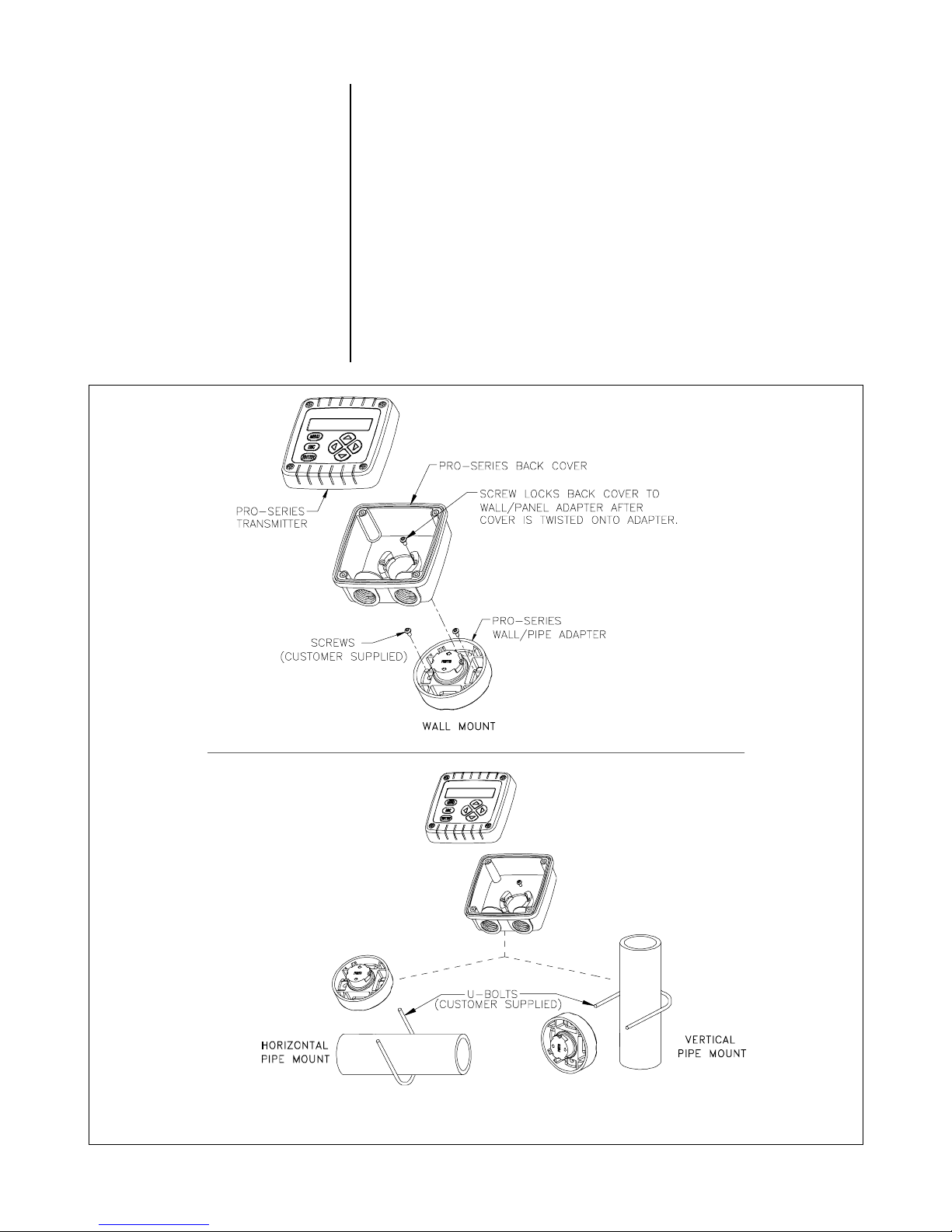
2.2 Wall and Pipe
Mounting
Figure 2-1 illustrates how to wall or pipe mount the transmitter using the supplied GLI hardware kit. Determine the
mounting method, and attach the hardware as shown.
1. Fasten the wall/pipe adapter to the wall or pipe.
2. Using a blunt tool, open both cable entry knockout
holes in the back cover.
3. Insert-and-twist the back cover onto the installed
wall/pipe adapter, and tighten its screw to lock back
cover onto adapter.
4. Attach transmitter to back cover using its four captive screws.
FIGURE 2-1 Wall and Pipe Mounting Details
PRO-series Model E3 Electrodeless Conductivity Transmitter Rev. 0-201
18
PART TW O - INSTALLATION SECTION 2 - MECHANICAL REQUIREMENTS
2.3 Panel Mounting
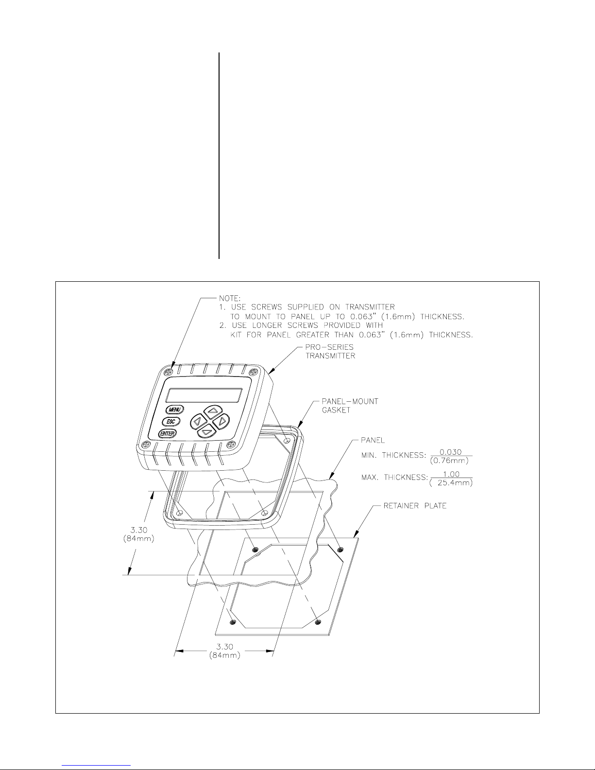
☞
Figure 2-2 illustrates how to panel mount the transmitter
using the supplied GLI panel mount hardware kit.
1. Cut a 3.30-inch (84 mm) square cutout hole in panel.
2. Position panel-mount gasket over cutout in front of
panel, and place retainer plate behind panel with its
four threaded inserts facing away from back of panel.
3. Attach transmitter to retainer plate using its four captive
screws.
NOTE: If panel is too thick, remove captive screws
from transmitter, and use longer screws provided in hardware kit.
Rev. 0-201 PRO-series Model E3 Electrodeless Conductivity Transmitter
FIGURE 2-2 Panel Mounting Details
19
PART TW O - INSTALLATION SECTION 2 - MECHANICAL REQUIREMENTS
2.4 Integral Sensor
Mounting
☞
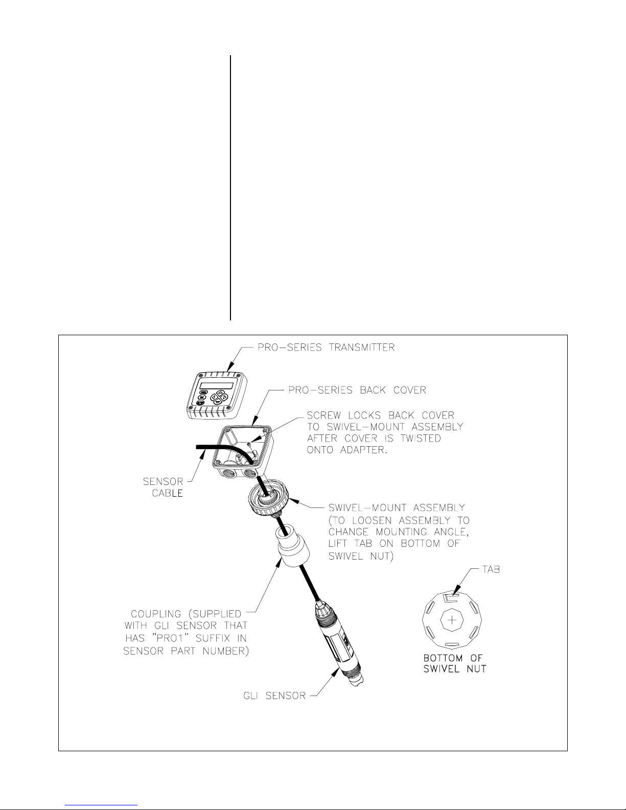
Figure 2-3 illustrates how to integrally mount the transmitter
onto a sensor using the supplied GLI mounting hardware kit.
1. Using a blunt tool, open knockout hole in bottom of
swivel ball for routing the sensor cable.
2. Attach swivel-mount assembly onto back end of sensor
using coupling provided with GLI sensor (only sensors
with “PRO1” suffix in their part number) or an appropriate-sized coupling that you provide.
3. Insert-and-twist back cover onto installed swivel-mount
assembly, and tighten its screw to lock back cover onto
swivel-mount assembly.
NOTE: To change mounting angle, loosen swivel-mount
assembly by lifting tab on bottom of swivel nut. Position to desired angle and re-tighten swivel nut.
4. Attach transmitter to back cover using its four captive screws.
FIGURE 2-3 Integral Sensor Mounting Details
PRO-series Model E3 Electrodeless Conductivity Transmitter Rev. 0-201
20
PART TW O - INSTALLATION SECTION 3 - ELECTRICAL CONNECTIONS
y
(
)
(
)
(Sig
)
(
)
(-)
(+)
(
(
)
ECTION
S
3
ELECTRICAL CONNECTIONS
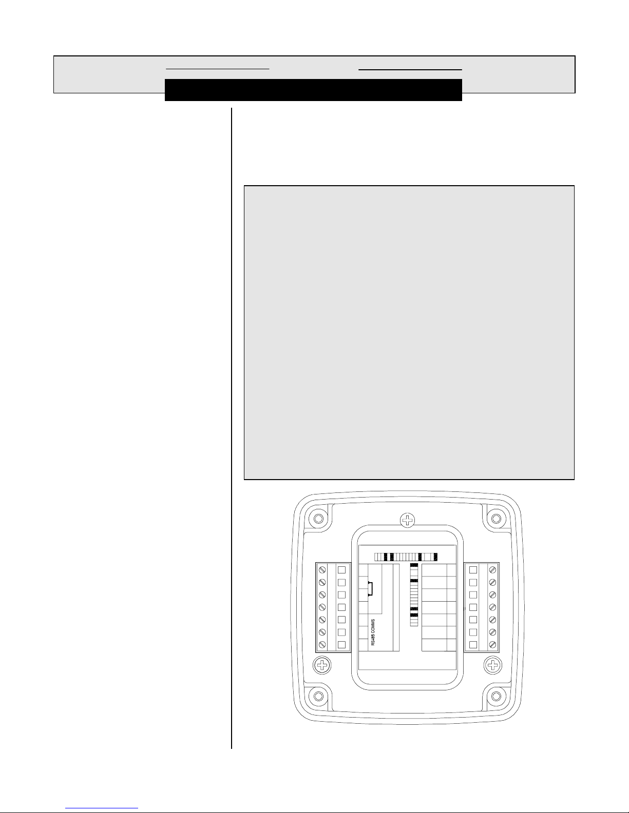
Figure 2-4 shows the terminal block arrangement and
terminal designations for the transmitter.
NOTE: All terminals are suitable for single wires up to 14
☞
AWG (2.5 mm2).
☞
Wiring Tip!
To comply with European Community (CE) electromagnetic
compatibility requirements, follow these general wiring guidelines:
1. Locate transmitter as far as possible from motors and other nonCE certified devices with excessive electromagnetic emissions.
2. Use GLI-specified ferrites and cables. Failure to do so may eliminate compliance. Locate all ferrites as close as possible to the
transmitter.
3. Loop these cables through the specified ferrite using the required
number of loops:
◆
DC Power Supply Cable (GLI 1W0980 two-conductor plus
shield): Connect cable shield to earth ground at the supply
end. Loop cable 4 times through ferrite (Fair-Rite Corp.
#2643102002 or equivalent).
◆
Sensor Cable: Keep cable shield as short as possible and
connect it to the SHIELD terminal. Loop cable 3-1/2 times
through ferrite (Fair-Rite Corp. #2643804502 or equivalent).
◆
Analog mA Output Cable (four-wire hookup only -- GLI
1W0980 two-conductor plus shield): Connect cable shield to
earth ground at the supply end. Loop cable 4 times through
ferrite (Fair-Rite Corp. #2643102002 or equivalent).
Rev. 0-201 PRO-series Model E3 Electrodeless Conductivity Transmitter
TB1 TB2
PRO-E-ESP: 0E Conductivit
Serial #: 47474747479
1
2
3
2-Wire Connection
4
5
6
7
14-30 VDC
(See manual for 3, 4 Wire Connections)
White
Drive
Blue
Drive0
Shield
Ground
Red
Temp
Yellow
Ground
NC
Green
nal
1
2
3
4
5
6
7
FIGURE 2-4 Transmitter Terminal Designations
21

PART TW O - INSTALLATION SECTION 3 - ELECTRICAL CONNECTIONS
)
)
(
)
)
(Sig
)
3.1 GLI Electrodeless
Conductivity Sensor
☞
☞
Refer to Figure 2-5 and connect the sensor (or interconnect) cable wires to Terminals 1 through 5 and to Terminal
7 on TB2, matching colors as indicated. (Terminal 6 is unused.)
Wiring Tip!
Route the sensor cable in 1/2-inch,
grounded metal conduit to protect it from moisture,
electrical noise, and mechanical damage.
For installations where the distance between sensor and
transmitter exceeds the sensor cable length, indirectly
connect the sensor to the transmitter using a junction box
and interconnect cable.
NOTE: Do not route the sensor cable in any conduit con-
taining AC or DC power wiring (“electrical noise”
may interfere with the sensor signal). Also, always
re-calibrate the system when the cable length between sensor and transmitter changes.
SENSOR
Depending on how transmitter is mounted, route the sensor
(or interconnect) cable into the transmitter as follows:
•
Wall/Pipe-mounted Transmitter: Route cable through left
side cable entry knockout hole in the back cover.
•
Panel-mounted Transmitter: Route cable behind panel to
the exposed TB2 terminal strip.
•
Integral Sensor-mounted Transmitter: Route cable
through swivel ball knockout hole and center hole in the
back cover. (Do not open left side cable entry knockout
hole in the back cover.)
White
Blue
Inner and
Outer Shields
Red
Yellow
Green
1 White (Drive-
2 Blue (Drive+
3 Shield
4 Red
5 Yellow (Ground
6
7 Green
Temp
nal
FIGURE 2-5 Connecting GLI Electrodeless Conductivity Sensor
PRO-series Model E3 Electrodeless Conductivity Transmitter Rev. 0-201
22
 Loading...