

GLI International F53 Operating Manual

OPERATING MANUAL
Model F53
Flow Monitor/Totalizer
(Universal-mount 1/2 DIN style)
Worldwide Headquarters and Sales:
GLI International, Inc.
9020 West Dean Road
Milwaukee, Wisconsin 53224
U.S.A.
In the interest of improving and updating its equipment, GLI reserves the right to alter specifications to equipment at any time.
Rev. 1-201 Model F53 Flow Monitor/Totalizer (universal-mount 1/2 DIN)
Phone:
Fax:
E-mail:
Web:
Represented By:
[414] 355-3601
[414] 355-8346
info@gliint.com
www.gliint.com
Viridor Instrumentation
A company
1
This operating manual and other GLI operating manuals
are available on GLI’s web site at gliint.com. when viewed
using Adobe’s free Acrobat reader. To get this reader, link
to Adobe through GLI’s web site or visit Adobe’s web site
at adobe.com.
Model F53 Flow Monitor/Totalizer (universal-mount 1/2 DIN) Rev. 1-201
2

IMPORTANT SAFETY INFORMATION
This analyzer is compliant with safety standards as outlined in:
FMRC Class Numbers 3600, 3611, and 3810 (U.S.A.)
CSA C22.2 No. 142 and C22.2 No. 213 (Canada)
EN 61010-1 (European Community)
Please read and observe the following:
•
Opening the analyzer door exposes you to line power voltage, if present, at terminals on TB2 and TB3
inside the enclosure. This may be hazardous. Always remove line power before entering this area in
the analyzer. However, the analyzer door assembly contains only low voltage and is completely safe
to handle.
•
Wiring or repairs should only be performed by qualified personnel and only to an unpowered analyzer.
•
Whenever it appears that analyzer safety is questionable, disable the analyzer to ensure against any
unintended operation. For example, an unsafe condition is likely when:
1) The analyzer appears visibly damaged.
2) The analyzer fails to operate properly or provide the intended measurements.
3) The analyzer has been stored for long periods at temperatures above 158°F (70°C).
•
This analyzer must be installed by personnel specially trained in accordance with relevant local codes
and instructions contained in this operating instruction manual. Observe the analyzer’s technical
specifications and input ratings. If one line of the line power mains is not neutral, use a double-pole
mains switch to disconnect the analyzer.
HELPFUL IDENTIFIERS
In addition to information on installation and operation, this instruction manual may contain
WARNINGS pertaining to user safety, CAUTIONS regarding possible instrument malfunction, and
NOTES on important, useful operating guidelines.
WARNING:
A WARNING LOOKS LIKE THIS. IT WARNS YOU OF THE POTENTIAL
FOR PERSONAL INJURY.
CAUTION:
A CAUTION LOOKS LIKE THIS. IT ALERTS YOU TO POSSIBLE
INSTRUMENT MALFUNCTION OR DAMAGE.
☞
NOTE: A note looks like this. It alerts you to important, useful operating
information.
Rev. 1-201 Model F53 Flow Monitor/Totalizer (universal-mount 1/2 DIN)
3
Definition of Equipment Symbols
This symbol
means CAUTION
and alerts you to possible danger or
instrument malfunction. Refer to this manual before proceeding.
This symbol
means that this is a protective ground terminal
alerts you to connect an earth ground to it.
This symbol
means that there is alternating current present
alerts you to be careful.
and
and
GLI International, Inc. warrants the Model F53 to be free from defects in material
or workmanship for a period of 2 years (24 months) from the date of shipment of
this product from our facility. A warranty claim will not be honored if defects are
not reported within the warranty period, or if GLI International determines that
defects or damages are due to normal wear, misapplication, lack of maintenance, abuse, improper installation, alteration, or abnormal conditions. GLI
International’s obligation under this warranty shall be limited to, at its option, replacement or repair of this product. The product must be returned to GLI
International, freight prepaid, for examination. The product must be thoroughly
cleaned and any process chemicals removed before it will be accepted for replacement or repair. GLI International’s liability shall not exceed the cost of the
product. Under no circumstances will GLI International be liable for any incidental or consequential damages, whether to person or property. GLI International
will not be liable for any other loss, damage or expense of any kind, including
loss of profits, resulting from the installation, use, or inability to use this product.
Model F53 Flow Monitor/Totalizer (universal-mount 1/2 DIN) Rev. 1-201
WARRANTY
4
CONDENSED OPERATING INSTRUCTIONS
This manual contains details for all operating aspects of the instrument. The following condensed instructions are provided to assist you in getting the instrument started up and operating as quickly as
possible.
sensor.
These condensed instructions are only for basic operation using a
To obtain a calculated measurement, use a non-GLI flow sensor or specific features of the in-
strument, refer to the appropriate sections in this manual for instructions.
A. CONNECTING SENSOR(S)
After properly mounting the analyzer (PART TWO, Section 2), connect up to four GLI impeller flow
sensor(s), matching wire colors to terminals as indicated:
GLI impeller flow
Sensor A Wire Colors
Red Terminal #10 on TB1 Red Terminal #14 on TB1
Black Terminal #11 on TB1 Black Terminal #15 on TB1
Cable shield Grounding strip lug Cable shield Grounding strip lug
Sensor B Wire Colors
Red Terminal #12 on TB1 Red Terminal #16 on TB1
Black Terminal #13 on TB1 Black Terminal #17 on TB1
Cable shield Grounding strip lug Cable shield Grounding strip lug
Connect To
Connect To
Sensor C Wire Colors
Sensor D Wire Colors
Connect To
Connect To
B. CONNECTING LINE POWER
Important:
Follow instructions in PART TWO, Section 3.5 to connect line power to the analyzer.
C. ADJUSTING DISPLAY CONTRAST
Ambient lighting conditions may make it necessary to adjust display contrast to improve visibility.
With the MEASURE screen displayed, press and hold
×
Ø
×
or
until attaining the desired contrast.
key
Ø
ENTER key
the
and simultaneously press the
The following flow rate and volume readout instructions configure Sensor A.
Set up other sensors in the same way using their respective menu screens.
D. SETTING FLOW RATE READOUT (multiplier, decimal, and measurement unit annunciator)
Displayed flow rates are always shown with a user-set multiplier.
Select measured flow rates to
be whole numbers or decimals (XXX.X or XX.XX), and choose the measurement unit annunciators.
1. Press
2. Use
Rev. 1-201 Model F53 Flow Monitor/Totalizer (universal-mount 1/2 DIN)
MENU key
Ø
to select the “CONFIGURE” line, and press
key
Ø
to display
&21),*8 5(
7(670$ ,1 7
(;,7
(continued on next page)
5
.
ENTER key
to display
.
CONDENSED OPERATING INSTRUCTIONS
D. SETTING FLOW RATE READOUT -- (continued)
Ø
key
3. Use
Ø
to select the “SENSOR A” line, and press
ENTER key
to display
.
4. With the “SET MULTIPLIER” line selected, press
Ø
. Use
Ø
With the desired choice displayed press
5. After the “SENSOR A” screen re-appears, use
ENTER key
press
to display a screen like
and
×
keys
×
to view the choices (x1, x10, x100, x1000, or x10000).
ENTER key
Ø
Ø
choices (XXXX, XXX.X, or XX.XX). With the desired choice displayed, press
ENTER key
to display a screen like
to enter this selection.
key
to select the “SET DECIMAL” line, and
. Use
Ø
Ø
and
×
keys
×
to view the
ENTER key
this selection.
Ø
key
6. After the “SENSOR A” screen re-appears, use
ENTER key
press
to display a screen like
choices. With the desired choice displayed, press
Ø
to select the “FLOW UNITS” line, and
ENTER key
Ø
. Use
Ø
to enter this selection.
and
×
keys
×
to view all
E. SETTING VOLUME READOUT (volume unit annunciator and totalizer reset mode)
Unlike flow rate, volume is shown only as a whole number without a multiplier.
Choose from a
variety of volume measurement unit annunciators. The totalizer is factory-set for auto reset, which
resets the displayed volume to zero after reaching its maximum limit. After automatically resetting,
the totalizer starts a new count. Conversely, the totalizer can be set to a manual reset mode to preserve the total volume. In the manual reset mode, the totalizer can be manually reset back to zero at
any time by using the “RESET VOL” function in the TEST/MAINT menu.
to enter
1. With the
ENTER key
press
to display a screen like
choices. With the desired choice displayed, press
2. After the “SENSOR A” screen re-appears, use
and press
ENTER key
both choices (AUTO RESET or MANUAL RESET). With the desired choice displayed, press
ENTER key
Model F53 Flow Monitor/Totalizer (universal-mount 1/2 DIN) Rev. 1-201
to enter this selection.
screen displayed, use
to display a screen like
(continued on next page)
6
Ø
key
Ø
to select the “VOLUME UNITS” line, and
Ø
. Use
ENTER key
Ø
key
Ø
to select the “TOTALIZER MODE” line,
to enter this selection.
Ø
. Use
and
Ø
and
Ø
×
keys
×
×
×
to view all
keys
to view
CONDENSED OPERATING INSTRUCTIONS
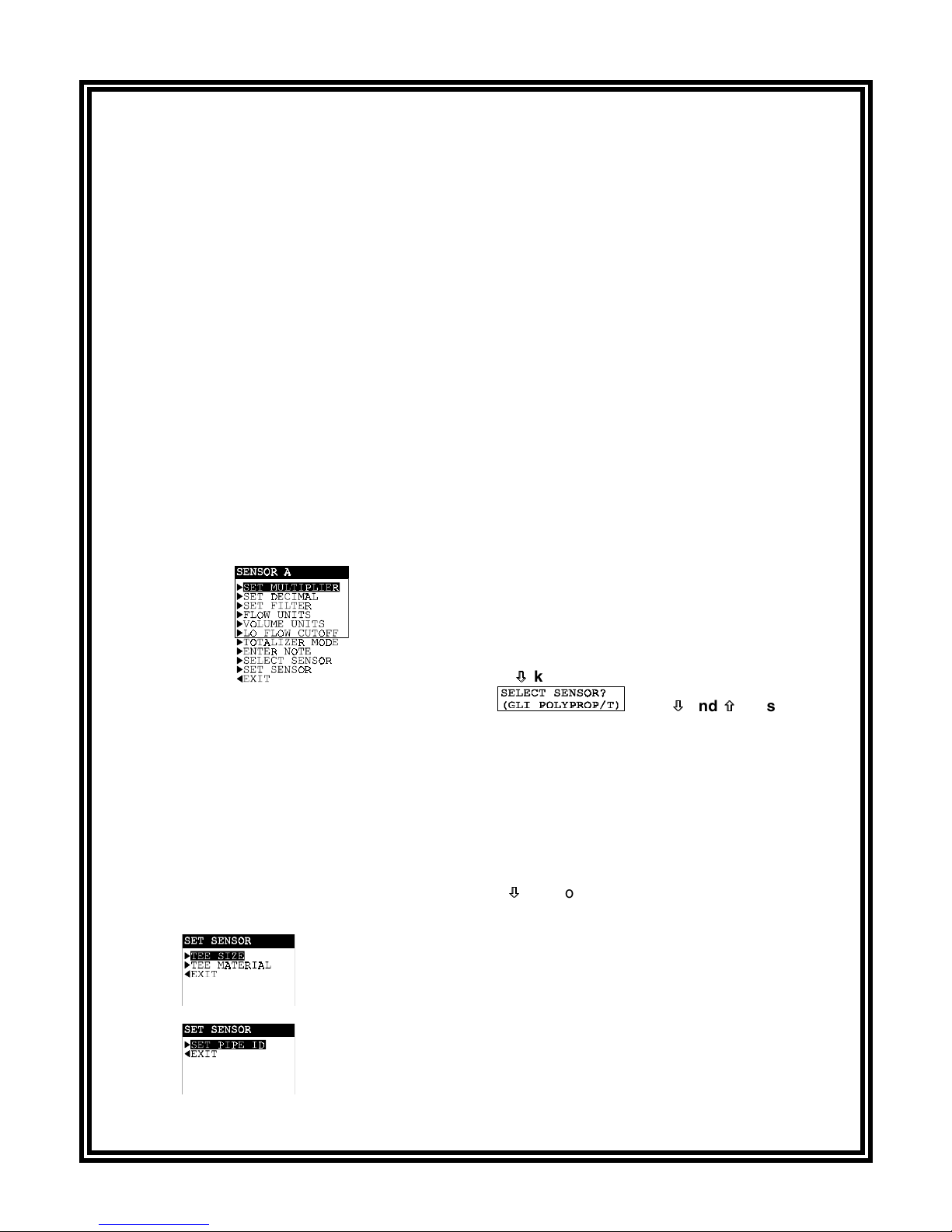
F. SELECTING SENSOR TYPE/ENTERING SENSOR DATA (calibration)
To configure/calibrate the analyzer so that measured values will accurately represent actual values,
you must select the sensor type and enter specific sensor-related data. This is a normal part of the
initial setup. The data you enter depends on the sensor being used:
•
GLI sensor mounted in tee:
•
GLI sensor mounted in pipe (using weldolet, pipe saddle or ball valve assembly):
the inside diameter of the pipe (SET PIPE ID).
•
Non-GLI sensor (any mounting):
OFFSET).
After entering appropriate sensor data, the analyzer is calibrated. Anytime thereafter, you can linearly offset measured flow readings by using the CALIBRATE menu.
only be considered when analyzer readings need to match a user-supplied “qualified reference” flow instrument.
See PART THREE, Sections 5.1 and 5.2 for complete adjustment details.
NOTE: The following configuration/calibration procedure is only for Sensor A and only for
GLI sensors. Configure/calibrate other sensors in the same way using their respective menu
screens. (To enter specific data for non-GLI sensors, see PART THREE, Section 4.2, subsection “SET SENSOR Data” under the “Non-GLI Sensor Setup” category.)
Enter the TEE SIZE and TEE MATERIAL.
Enter a slope value (SET SLOPE) and an offset value (SET
Calibration adjustment should
Enter
Ø
key
1. With the screen displayed, use
and press
ENTER key
to display a screen like
Ø
the type of GLI sensor and mounting arrangement you are using:
•
GLI PIPE MOUNT--------for sensor mounted in pipe using weldolet, pipe saddle or ball valve
•
GLI POLYPROP/T -------for polypropylene sensor mounted in tee
•
GLI PVDF/T ---------------for PVDF sensor mounted in tee
•
GLI 316SS/T --------------for stainless steel-sleeved sensor with 2-inch NPT hex adapter mounted in tee
•
GLI BRASS/T -------------for brass-sleeved sensor with 2-inch NPT hex adapter mounted in tee)
2. With the appropriate choice displayed, press
3. After the “SENSOR A” screen re-appears, use
pending on the selected sensor, pressing
ENTER key
Ø
key
Ø
ENTER key
displays:
when “GLI POLYPROP/T,” “PVDF/T,” “316SS/T” or “BRASS/T” was selected.
when “GLI PIPE MOUNT” was selected.
to select the “SELECT SENSOR” line,
. Use
Ø
Ø
and
×
keys
×
to select
to enter this selection.
to select the “SET SENSOR” line. De-
Rev. 1-201 Model F53 Flow Monitor/Totalizer (universal-mount 1/2 DIN)
(continued on next page.)
7
CONDENSED OPERATING INSTRUCTIONS
F. SELECTING SENSOR TYPE/ENTERING SENSOR DATA -- (continued)
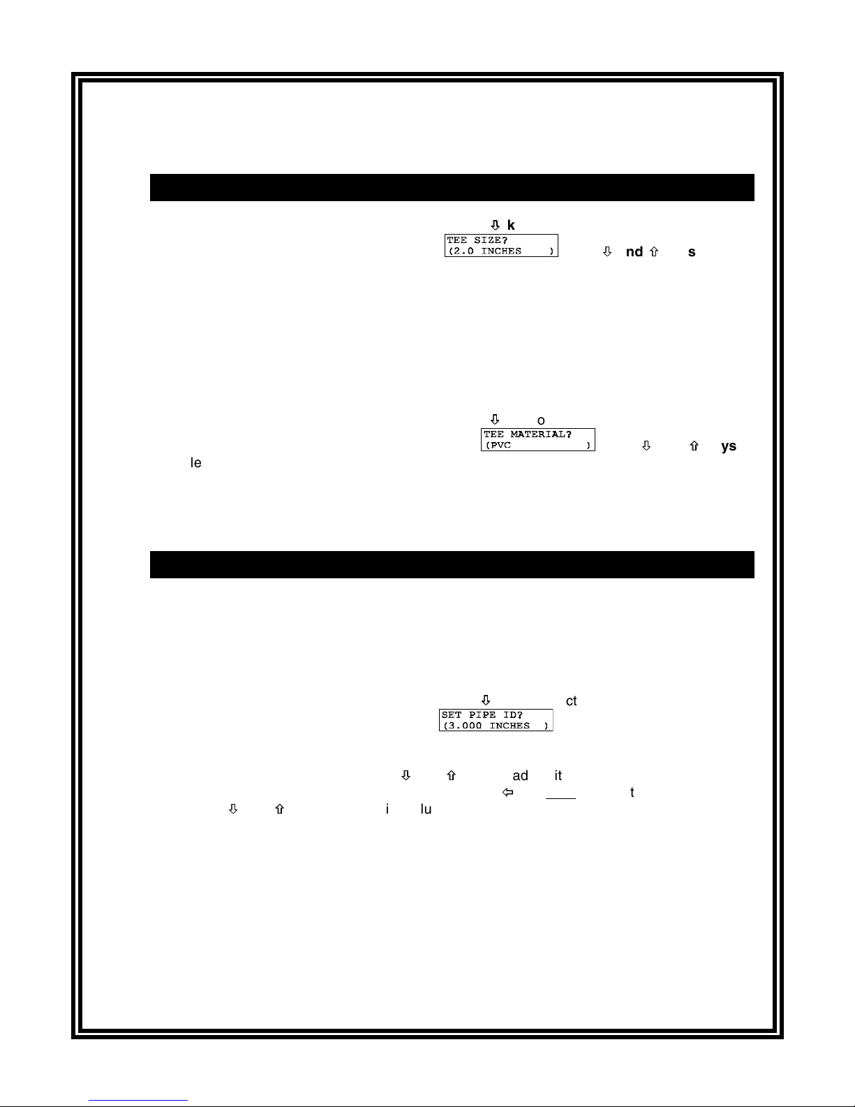
GLI Tee Mount Sensor Setup (select TEE SIZE and TEE MATERIAL)
Ø
key
A. With the “SET SENSOR” screen displayed, use
Ø
to select the “TEE SIZE” line and
press
ENTER key
to display a screen like
. Use
Ø
Ø
and
×
keys
×
to select
the tee size in which the sensor is mounted:
0.5 INCHES
•
0.75 INCHES
•
1.0 INCHES
•
1 IN. MHF15L2*
•
*Select only when using a GLI PVC 1-inch MHF15L2 tee for higher flow range (up to 65 GPM).
B. With the appropriate tee size displayed, press
C. After the “SET SENSOR” screen re-appears, use
and press
ENTER key
to display a screen like
select the tee material, and press
1.25 INCHES
•
1.5 INCHES
•
2.0 INCHES
•
2.5 INCHES
•
ENTER key
3.0 INCHES
•
4.0 INCHES
•
ENTER key
Ø
Ø
to enter this selection.
key
to select the “TEE MATERIAL” line
Ø
and
. Use
Ø
×
keys
×
to
to enter this selection. (Selected tee size de-
termines available tee materials.)
This completes GLI tee mount sensor data entry/calibration. The analyzer is now ready to measure Sensor A flow/volume.
GLI Pipe Mount Sensor Setup (SET PIPE ID)
A. Determine actual inside pipe diameter. Actually measure it or refer to an appropriate table.
NOTE: Pipe IDs for commonly-used Schedule 40 and Schedule 80 pipes are listed in Ta-
bles A and B in PART THREE, Section 4.2 under the “SET SENSOR Data”
subheading.
B. With the “SET SENSOR” screen displayed, use
ENTER key
press
C. Adjust the displayed value to exactly match the actual pipe ID (inside diameter). Starting with
the extreme right blinking digit, use
pressed, the faster the value changes.) Then press
use the
Ø
Ø
and
×
keys
×
played, and press
This completes GLI pipe mount sensor data entry/calibration. The analyzer is now ready to measure
Sensor A flow/volume.
G. COMPLETING ANALYZER CONFIGURATION
To further configure the analyzer to your application requirements, use the appropriate CONFIGURE
screens to make selections and “key in” values. Refer to PART THREE, Section 4 for complete configuration details.
Model F53 Flow Monitor/Totalizer (universal-mount 1/2 DIN) Rev. 1-201
Ø
key
Ø
to select the “SET PIPE ID” line and
to display a screen like
Ø
and
Ø
×
×
keys
to adjust its value. (The longer the key is
Õ
Õ
.
once to select the next digit, and
key
to adjust its value. Repeat this procedure until desired value is dis-
ENTER key
to enter it.
8

TABLE OF CONTENTS
PART ONE - INTRODUCTION
SECTION 1 GENERAL INFORMATION
1.1 Capability Highlights ........................................................................15-17
1.2 Modular Construction ............................................................................17
1.3 Retained Configuration Values .............................................................18
1.4 Analyzer Serial Number ........................................................................18
1.5 EMI/RFI Immunity..................................................................................18
SECTION 2 SPECIFICATIONS
....................................................................................19-20
PART TWO - INSTALLATION
SECTION 1 UNPACKING
SECTION 2 MECHANICAL REQUIREMENTS
2.1 Location................................................................................................. 21
2.2 Mounting...........................................................................................21-23
2.3 Conduit Hole Requirements ..................................................................23
SECTION 3 ELECTRICAL CONNECTIONS
3.1 Flow Sensor(s) .................................................................................25-26
3.2 Analog Outputs.................................................................................26-27
3.3 Relay Outputs...................................................................................27-28
3.4 Pulsed Outputs (contact closure) ..........................................................28
3.5 Closed Contact TTL Input .....................................................................28
3.6 Line Power ............................................................................................29
.................................................................................................21
PART THREE - OPERATION
SECTION 1 USER INTERFACE
1.1 Display .............................................................................................30-31
1.2 Keypad .............................................................................................31-32
1.3 MEASURE Screen (normal display mode).......................................32-33
SECTION 2 MENU STRUCTURE
2.1 Displaying Main Branch Selection Screen ............................................34
2.2 Displaying Top-level Menu Screens.................................................34-35
2.3 Displaying Submenu Screens ...............................................................35
2.4 Adjusting Edit/Selection Screen Values ................................................36
2.5 Entering (Storing) Edit/Selection Screen Values/Choices..................... 36
Rev. 1-201 Model F53 Flow Monitor/Totalizer (universal-mount 1/2 DIN)
9

TABLE OF CONTENTS (continued)
SECTION 3 ADJUSTING DISPLAY CONTRAST
SECTION 4 ANALYZER CONFIGURATION
4.1 Selecting LANGUAGE to Operate Analyzer.......................................... 37
4.2 Configuring Sensors (A, B, C, and D):
SET MULTIPLIER (for displayed flow rate).................................38-39
SET DECIMAL (for displayed flow rate)........................................... 39
SET FILTER Time.......................................................................39-40
Select FLOW UNITS (for displayed flow rate) ............................40-41
Select VOLUME UNITS (for displayed volume)...............................41
Set LO FLOW CUTOFF Limit ..........................................................42
Select TOTALIZER MODE (auto or manual reset) .....................42-43
ENTER NOTE (top line of MEASURE screen).................................43
SELECT SENSOR Type.............................................................43-44
SET SENSOR Data:
GLI Tee Mount -- Select TEE SIZE and TEE MATERIAL......44-45
GLI Pipe Mount -- SET PIPE ID..................................................46
Non-GLI Sensor -- SET SLOPE and SET OFFSET Values......47-48
4.3 Configuring CALCULATION Measurement:
SET VARIABLE X ............................................................................ 49
SET VARIABLE Y ............................................................................ 50
SET FORMULA (X/Y, X-Y, X+Y, or [X/Y] x 100) .............................. 50
Select DISPLAY FORMAT (decimal and multiplier)....................51-52
4.4 Configuring Analog Outputs (1 and 2):
SET PARAMETER (representation) ...........................................53-54
SET 0/4 mA and 20 mA VALUES................................................54-55
SET FILTER Time............................................................................ 55
Select SCALE 0 mA/4 mA (low endpoint) ........................................ 55
4.5 Configuring Relays (A, B, C, and D):
SET PARAMETER (representation) ...........................................56-57
SET FUNCTION Mode (alarm, control or status)............................. 57
ACTIVATION (configuration values) ...........................................58-59
4.6 Configuring Pulse Outputs (A and B):
SET PARAMETER (representation) ................................................60
SET VOLUME Increment ............................................................60-61
Set PULSE DURATION ...................................................................61
4.7 SET PASSCODE (feature enabled or disabled) ................................... 62
4.8 Configuration Setting Summary (ranges/choices and defaults) .......63-65
.............................................................36
SECTION 5 ANALYZER CALIBRATION
5.1 Important Information ............................................................................66
5.2 OFFSET BY or SET TO Calibration Adjustment ..............................67-68
5.3 Analog Outputs (1 and 2) Calibration...............................................68-69
Model F53 Flow Monitor/Totalizer (universal-mount 1/2 DIN) Rev. 1-201
10

TABLE OF CONTENTS (continued)
SECTION 6 TEST/MAINTENANCE
6.1 STATUS Checking (analyzer, sensors, and relays) .........................70-71
6.2 RESET VOL (A, B, C, and D) ................................................................72
6.3 HOLD OUTPUTS ..................................................................................72
6.4 OVERFEED RESET (relay timers)........................................................ 73
6.5 OUTPUT (1 and 2) Analog Test Signals ..........................................73-74
6.6 RELAY (A, B, C, and D) Operating Test................................................74
6.7 PULSE (A and B) Operating Test..........................................................75
6.8 EPROM VERSION Checking ................................................................75
6.9 SELECT SIM Measurement .................................................................. 76
6.10 SIM Setting............................................................................................ 77
6.11 RESET CONFIGURE ............................................................................78
SECTION 7 RELAY OVERFEED TIMER FEATURE
7.1 Why Use an Overfeed Timer.................................................................79
7.2 Relay Overfeed Timer Setup Guidelines...............................................79
7.3 Overfeed Timer “Timeout” Operation .................................................... 79
7.4 Resetting Overfeed Timers ...................................................................79
7.5 Interactions with Other Analyzer Functions......................................79-80
SECTION 8 HART OPTION
8.1 Introduction ...........................................................................................81
8.2 Analyzer Operating Modes for HART Network.................................82-83
8.3 SINGLE MODE (Point-to-Point) Wiring Arrangement ...........................83
8.4 MULTI-DROP Wiring Arrangement .......................................................84
8.5 HART Preferences Setup:
Changing Polling Address ...............................................................85
Viewing Number of Required Preambles ....................................85-86
8.6 Device Preferences Setup:
Viewing Final Assembly Number .....................................................86
Viewing Model Number...............................................................86-87
Viewing Manufacturer ...................................................................... 87
Assigning a Tag ............................................................................... 87
Assigning a Descriptor .....................................................................88
Assigning a Message....................................................................... 88
Assigning User-defined Date ......................................................88-89
Viewing Identification (ID) ................................................................ 89
Viewing Revisions............................................................................ 89
8.7 “Master Reset” Function........................................................................90
8.8 “Refresh” Function ................................................................................ 90
8.9 Protocol Command Set for PC Programming ........................................90
Rev. 1-201 Model F53 Flow Monitor/Totalizer (universal-mount 1/2 DIN)
11

TABLE OF CONTENTS (continued)
PART FOUR - SERVICE AND MAINTENANCE
SECTION 1 GENERAL INFORMATION
1.1 Inspecting Sensor Cables .....................................................................91
1.2 Replacing Fuse(s) .................................................................................91
1.3 Replacing Relays ..................................................................................91
SECTION 2 PRESERVING MEASUREMENT ACCURACY
2.1 Keeping Sensor(s) Clean ......................................................................92
2.2 Avoiding Electrical Interference............................................................. 92
SECTION 3 TROUBLESHOOTING
3.1 Checking Electrical Connections...........................................................92
3.2 Verifying Sensor Operation ...................................................................92
3.3 Verifying Analyzer Operation ...........................................................92-93
3.4 Verifying Interconnect Cable Integrity ...................................................93
SECTION 4 ANALYZER REPAIR/RETURN
4.1 Customer Assistance.............................................................................94
4.2 Repair/Return Policy .............................................................................94
PART FIVE - SPARE PARTS AND ACCESSORIES
......................................................................................................................95
Model F53 Flow Monitor/Totalizer (universal-mount 1/2 DIN) Rev. 1-201
12

TABLE OF CONTENTS (continued)
ILLUSTRATIONS
Figure 1-1
Figure 2-1
Figure 2-2
Figure 2-3
Figure 2-4
Figure 2-5
Figure 2-6
Figure 2-7
Figure 2-8
Figure 3-1
Figure 3-2
Figure 3-3
Figure 3-4
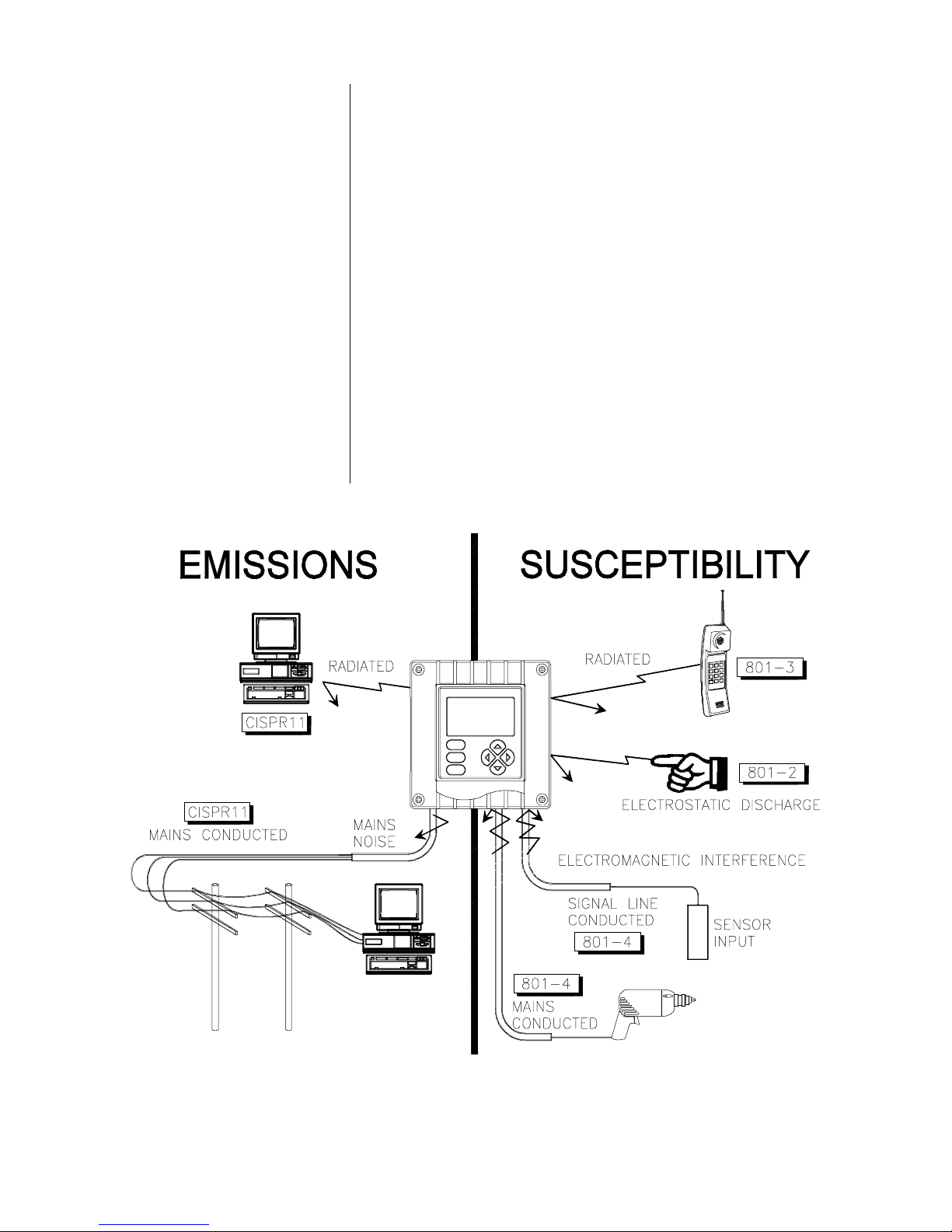
EMI/RFI Immunity Diagram..............................................................................................18
Analyzer Mounting Arrangements ....................................................................................22
Analyzer Installation Dimension Details............................................................................23
Analyzer Terminal Block Designations .............................................................................25
Connecting Flow Sensor(s) ..............................................................................................26
Connecting Control/Alarm Device(s) to Electromechanical Relay(s).................................28
Connecting 115 Volt Single Phase Line Power (90-130 VAC)...........................................29
Connecting 230 Volt Single Phase Line Power (180-260 VAC).........................................29
Connecting 230 Volt Split Phase Line Power (180-260 VAC)............................................29
Analyzer Keypad..............................................................................................................31
Location of SINGLE MODE/MULTI-DROP Switch (HART-equipped analyzers only) ........83
HART SINGLE MODE (Point-to-Point) Wiring Arrangement (for single analyzer).............83
HART MULTI-DROP Wiring Arrangement (for multiple analyzer network)........................84
Table A
Table B
Table C
Table D
Table E
Rev. 1-201 Model F53 Flow Monitor/Totalizer (universal-mount 1/2 DIN)
Schedule 40 Pipe IDs.......................................................................................................46
Schedule 80 Pipe IDs.......................................................................................................46
Relay Configuration Settings............................................................................................58
Analyzer Configuration Settings (Ranges/Choices and Defaults) .................................63-65
Relay Overfeed Timer Interactions with Other Analyzer Functions...................................80
TABLES
13

Model F53 Flow Monitor/Totalizer (universal-mount 1/2 DIN) Rev. 1-201
14
PART ONE - INTRODUCTION SECTION 1 - GENERAL INFORMATION
PART ONE - INTRODUCTION
ECTION
1.1 Capability Highlights
Sensor Inputs
S
GENERAL INFORMATION
The analyzer has four sensor inputs to independently measure
up to four flow rates/volumes. Each input can accept:
•
Any GLI IMPELLER flow sensor
•
A NON-GLI SENSOR with a 0-2000 Hz. output
(paddle wheel, turbine, vortex, etc.). However, its
slope and offset values must be determined and
entered to calibrate the analyzer.
1
MEASURE Screen
Depending on the number of sensors used, the MEASURE
screen (normal display mode) can show up to 8 separate
sensor readouts, 8 combined data readouts, and a calcu-
ÕÕ or
lated value (if configured) by pressing
Separate Sensor Readouts
1. SENSOR A flow rate with multiplier
2. SENSOR B flow rate with multiplier
3. SENSOR C flow rate with multiplier
4. SENSOR D flow rate with multiplier
5. SENSOR A volume (no multiplier)
6. SENSOR B volume (no multiplier)
7. SENSOR C volume (no multiplier)
8. SENSOR D volume (no multiplier)
Combined Data Readouts
1. Sensor A flow rate and volume
2. Sensor B flow rate and volume
3. Sensor C flow rate and volume
4. Sensor D flow rate and volume
5. Sensor A and Sensor B flow rates
6. Sensor A and Sensor B volumes
7. Sensor C and Sensor D flow rates
8. Sensor C and Sensor D volumes
CALCULATED* Measurement Readout*
Calculation can be X-Y, X+Y, X/Y, or [X/Y] x 100 with selectable X and Y
variables representing specific sensor flow rates and volumes
ÖÖ key:
Rev. 1-201 Model F53 Flow Monitor/Totalizer (universal-mount 1/2 DIN)
*Calculated measurement can only be provided when two sensors are
used and analyzer has been correctly configured for CALCULATION.
The bottom auxiliary display line, shown in reverse video on
the MEASURE screen, can be changed by pressing the
and
×× keys to show analog output 1 and 2 mA values.
15
Ø
Ø

PART ONE - INTRODUCTION SECTION 1 - GENERAL INFORMATION
Passcode-protected
Access
Calibration
For security, you can enable a passcode feature to restrict access to configuration and calibration settings to authorized
personnel only. See PART THREE, Section 4.7 for details.
Calibration is actually achieved by independently configuring each sensor, which is a normal part of the initial setup.
First, select the type of sensor being used:
•
GLI PIPE MOUNT -------for sensor mounted in pipe using weldolet, pipe
saddle or ball valve assembly
•
GLI POLYPROP/T ------- for polypropylene sensor mounted in tee
•
GLI PVDF/T ---------------for PVDF sensor mounted in tee
•
GLI 316SS/T --------------for stainless steel-sleeved sensor with 2-inch NPT
hex adapter mounted in tee
•
GLI BRASS/T -------------for brass-sleeved sensor with 2-inch NPT hex
adapter mounted in tee
•
NON-GLI Sensor---------for sensor with 0-2000 Hz. output (any mounting)
For GLI PIPE MOUNT, enter the internal diameter of the
pipe in which the sensor will be installed. When using a GLI
tee-mounted sensor, enter the tee size and tee material. For
a NON-GLI SENSOR, determine and enter appropriate
SLOPE and OFFSET values.
Analog Outputs
The CALIBRATE menu enables you to linearly offset measured flow readings one of two ways by using the:
•
OFFSET BY method to enter a “+” or “-” offset value.
•
SET TO method to enter a known measured value.
See PART THREE, Sections 5.1 and 5.2 for details. Also,
the mA values for each analog output can be calibrated
(Section 5.3).
The analyzer provides two isolated analog outputs (1 and
2). Each output can be set to be 0-20 mA or 4-20 mA, and
assigned to represent one of these
•
Sensor A flow rate
•
Sensor B flow rate
•
Sensor C flow rate
•
Sensor D flow rate
•
Sensor A volume
*An analog output can only represent the calculated measurement when two sensors
are used and the analyzer has been correctly configured for CALCULATION.
•
Sensor B volume
•
Sensor C volume
•
Sensor D volume
•
Calculated measurement*
measurements
:
Model F53 Flow Monitor/Totalizer (universal-mount 1/2 DIN) Rev. 1-201
Parameter (or calculated measurement) values can be entered to define the endpoints at which the minimum and
maximum analog output values are desired. For analog output setup details, refer to PART THREE, Section 4.4.
16

PART ONE - INTRODUCTION SECTION 1 - GENERAL INFORMATION
Relays
☞
The analyzer has four electromechanical relays with SPDT
contacts. Each relay can be set to function as a CONTROL,
ALARM or STATUS relay. CONTROL and ALARM relays
can be assigned to be driven by one of these:
•
Sensor A flow rate
•
Sensor B flow rate
•
Sensor C flow rate
•
Sensor D flow rate
•
Sensor A volume
*A relay can only be driven by the calculated measurement when two sensors
are used and the analyzer has been correctly configured for CALCULATION.
•
Sensor B volume
•
Sensor C volume
•
Sensor D volume
•
Calculated measurement*
NOTE: When a relay is set to function as a STATUS relay,
it is no longer configurable. Instead, it becomes a
dedicated system diagnostic-only alarm relay that
automatically energizes when the “WARNING
CHECK STATUS” message flashes on the
MEASURE screen. This occurs when the analyzer
detects a “fail” diagnostic condition. See PART
THREE, Section 6.1 for more details.
Pulsed Outputs
1.2 Modular Construction
For relay setup details, refer to PART THREE, Section 4.5.
The analyzer provides two SPDT pulsed contact closure
outputs (A and B) for remote use such as counting or
pumping. Each pulsed output can be assigned to represent
any measured volume, and set to activate at a desired volume increment for a preset time duration. Refer to PART
THREE, Section 4.6 for setup details.
The modular construction of the analyzer simplifies field
servicing and provides electrical safety. The front door/
keypad assembly uses voltages no greater than 24 VDC,
and is completely safe to handle.
Opening the analyzer door accesses terminals inside the
enclosure for electrical connections. Line power must be
connected to specifically designated terminals on TB3.
Rev. 1-201 Model F53 Flow Monitor/Totalizer (universal-mount 1/2 DIN)
WARNING:
REMOVE LINE POWER BEFORE NEARING THIS AREA
TO PREVENT ELECTRICAL SHOCK.
17
PART ONE - INTRODUCTION SECTION 1 - GENERAL INFORMATION
1.3 Retained
Configuration Values
1.4 Analyzer
Serial Number
1.5 EMI/RFI Immunity
All user-entered configuration values are retained indefinitely, even if power is lost or turned off. The non-volatile
analyzer memory does not require battery backup.
A label with the analyzer model number, serial number,
build date, and other items is located on top of the enclosure.
The analyzer is designed to provide protection from most
normally encountered electromagnetic interference. This
protection exceeds US standards and meets European
IEC 801-series testing for electromagnetic and radio frequency emissions and susceptibility. Refer to Figure 1-1
and the specifications in Section 2.1 for more information.
Model F53 Flow Monitor/Totalizer (universal-mount 1/2 DIN) Rev. 1-201
FIGURE 1-1 EMI/RFI Immunity Diagram
18

PART ONE - INTRODUCTION SECTION 2 - SPECIFICATIONS
ECTION
S
2
SPECIFICATIONS
2.1 Operational
Display....................................... Graphic dot matrix LCD, 128 x 64 pixels with
LED backlighting; 1/2 inch (13 mm) main
character height; 1/8 inch (3 mm) auxiliary
information character height; menu screens
contain up to six text lines
Measurement Selectable Ranges
Flow Rate (all sensors).......... 0-9999, 0-999.9 or 0-99.99 with selectable
flow rate units and multiplier
Volume (all sensors) ............. 0-999,999,999 with selectable volume units
Calculation (X and Y are selectable):
X-Y: Flow.......................... 0-9999, 0-999.9 or 99.99 w/selected multiplier
Volume..................... 0-999,999,999 in preset volume units
X+Y: Flow.......................... 0-9999, 0-999.9 or 99.99 w/selected multiplier
Volume..................... 0-999,999,999 in preset volume units
X/Y (flow or volume) .......... 0-9999, 0-999.9 or 99.99 (no units)
[X/Y] x 100......................... 0-999% pass ratio
Analog Outputs (1 and 2) ...... 0.00-20.00 mA or 4.00-20.00 mA
Ambient Conditions:
Operation.............................. -4 to +140°F (-20 to +60°C); 0-95% relative
humidity, non-condensing
Storage................................. -22 to +158°F (-30 to +70°C); 0-95% relative
humidity, non-condensing
Relays: Types/Outputs .................Four electromechanical relays; SPDT (Form C)
contacts; U.L. rated 5A 115/230 VAC, 5A @ 30
VDC resistive
Operational Mode ......... Each relay (A, B, C, and D) can be assigned
to be driven by one of these measurements:
•
Sensor A flow rate
•
Sensor B flow rate
•
Sensor C flow rate
•
Sensor D flow rate
•
Sensor A volume
Function Modes:
Control.................... Settings for high/low phasing, setpoint, dead-
band, overfeed timer, off delay, and on delay
Alarm .........................Settings for low alarm point, low alarm point
deadband, high alarm point, high alarm point
deadband, off delay, and on delay
Status.........................Not configurable; relay only activates when a
sensor or analyzer “fail” diagnostic WARNING
condition exists
Indicators.........................Relay A, B, C, and D annunciators indicate
respective relay status
Sensor-to-Analyzer Distance:
GLI Impeller Sensors ............ 2000 ft. (610 m) maximum
Non-GLI Sensors .................. 300 ft. (91 m) maximum
•
Sensor B volume
•
Sensor C volume
•
Sensor D volume
•
Calculated measurement
Rev. 1-201 Model F53 Flow Monitor/Totalizer (universal-mount 1/2 DIN)
Power Requirements .................. 90-130 VAC, 50/60 Hz. (10 VA max.) or
180-260 VAC, 50/60 Hz. (10 VA max.)
19

PART ONE - INTRODUCTION SECTION 2 - SPECIFICATIONS
Calibration Adjust: Offset By ..... Enter a “+” or “-” offset value that is respec-
tively added to or subtracted from
measured flow readings for a linear offset
Set To ......... Enter measurement value (derived from
qualified reference instrument reading) to
linearly offset measured flow reading
NOTE:
Calibration is actually achieved by independently configuring each
sensor, which is a normal part of the initial setup.
Analog Outputs .......................... Two isolated 0/4-20 mA outputs; each with 0.004
mA (12-bit) resolution and capability to drive up
to 600 ohm loads; each output can be assigned
to represent one of these measurem ents:
•
Sensor A flow rate• Sensor B volume
NOTE:
•
Sensor B flow rate
•
Sensor C flow rate• Sensor D volume
•
Sensor D flow rate
•
Sensor A volume
Parameter (or calculated measurement) values can be entered to
•
Sensor C volume
•
Calculated measurement
define the endpoints at which the minimum and maximum mA output
values are desired (range expand).
Pulsed Outputs .......................... Two SPDT contact closures; each pulsed
output can represent a selected measured
volume, and activate at a user-set volume
increment for a desired time duration
Communication: RS-232 ........... Enables configuration and retrieval of measured
data for one analyzer using IBM-compatible PC
and optional GLI software tool kit
HART.............. Enables configuration and retrieval of measured
data for multiple analyzers over a communication link using appropriate hand-held terminal or
data system with HART software
2.2 Analyzer Performance
(Electrical, Analog Outputs)
2.3 Mechanical
Memory Backup (non-volatile) .... All user settings are retained indefinitely in
memory (EEPROM)
EMI/RFI Conformance................ Exceeds US and meets European standards
for conducted and radiated emissions and
immunity; certified CE compliant for applications as specified by EN 50081-1 for
emissions and EN 50082-2 for immunity
Electrical Certifications:
General Purpose (pending) ..... UL, C-UL, FM, and CENELEC
Class 1, Division 2 (pending) .. UL, C-UL, and FM: Groups A, B, C, D, F, and G
Zone 2 (pending) .................... CENELEC: Group IIC
Accuracy.................................... ± 0.1% of span
Sensitivity .................................. ± 0.1% of span
Repeatability .............................. ± 0.05% of span
Temperature Drift....................... Zero and Span: ± 0.02% of span per °C
Response Time .......................... 1-60 seconds to 90% of value upon step change
Enclosure................................... NEMA 4X; polycarbonate face panel, epoxy-
coated cast aluminum door and case with four
1/2 inch (13 mm) conduit holes; nylon mounting bracket, and stainless steel hardware
Mounting Configurations............. Panel, surface, and pipe (horizontal and
vertical) mounting
Net Weight................................. 3.5 lbs. (1.6 kg) approximately
Model F53 Flow Monitor/Totalizer (universal-mount 1/2 DIN) Rev. 1-201
20
PART TW O - INSTALLATION SECTION 1 - UNPACKING
PART TWO - INSTALLATION
ECTION
S
UNPACKING
After unpacking, it is recommended to save the shipping
carton and packing materials in case the instrument must be
stored or re-shipped. Inspect the equipment and packing
materials for signs of shipping damage. If there is any evidence of damage, notify the transit carrier immediately.
ECTION
S
MECHANICAL REQUIREMENTS
1
2
2.1 Location
1. It is recommended to locate the analyzer as close as
possible to the installed flow sensor. Depending on the
sensor type, the maximum allowable distance between
the sensor and analyzer is:
Any GLI Sensor:
•
NON-GLI SENSOR:
•
2. Mount the analyzer in a location that is:
➥
Clean and dry where there is little or no vibration.
➥
Protected from corrosive fluids.
➥
Within ambient temperature limits (-4 to +140°F or
-20 to +60°C).
EXPOSING THE ANALYZER TO DIRECT
SUNLIGHT MAY INCREASE THE OPERATING
TEMPERATURE ABOVE ITS SPECIFIED
LIMIT, AND DECREASE DISPLAY VISIBILITY.
RECOMMENDATION: IN SEVERE CASES,
USE A GLI SUN SHIELD (P/N 1000G3088-001).
2000 feet (610 m)
300 feet (91 m)
CAUTION:
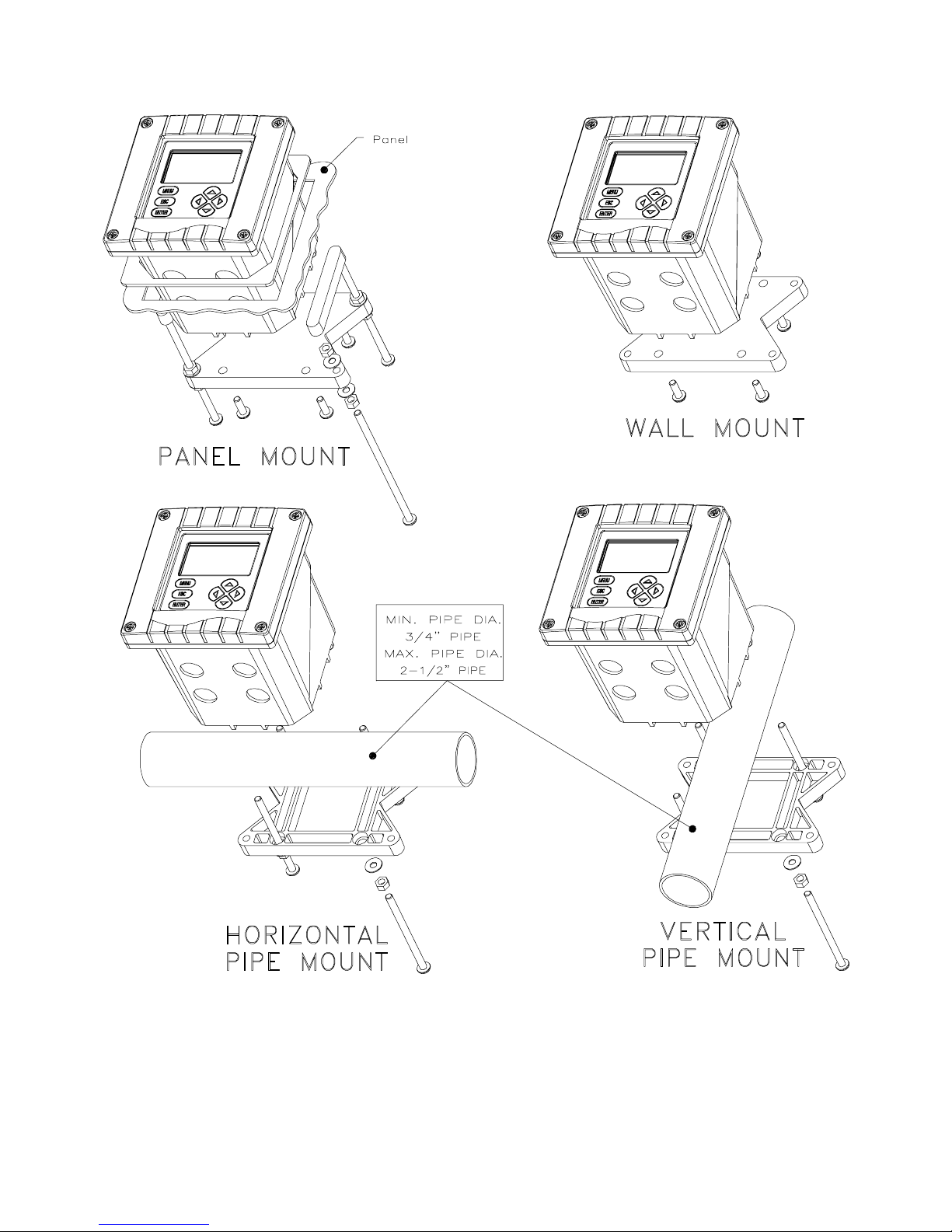
2.2 Mounting
Rev. 1-201 Model F53 Flow Monitor/Totalizer (universal-mount 1/2 DIN)
Figure 2-1 illustrates the various ways to mount the analyzer using the supplied bracket and hardware. Determine
the mounting method and attach the hardware as shown in
the respective illustration. Refer to Figure 2-2 for analyzer
installation dimension details.
21
PART TW O - INSTALLATION SECTION 2 - MECHANICAL REQUIREMENTS
FIGURE 2-1 Analyzer Mounting Arrangements
Model F53 Flow Monitor/Totalizer (universal-mount 1/2 DIN) Rev. 1-201
22
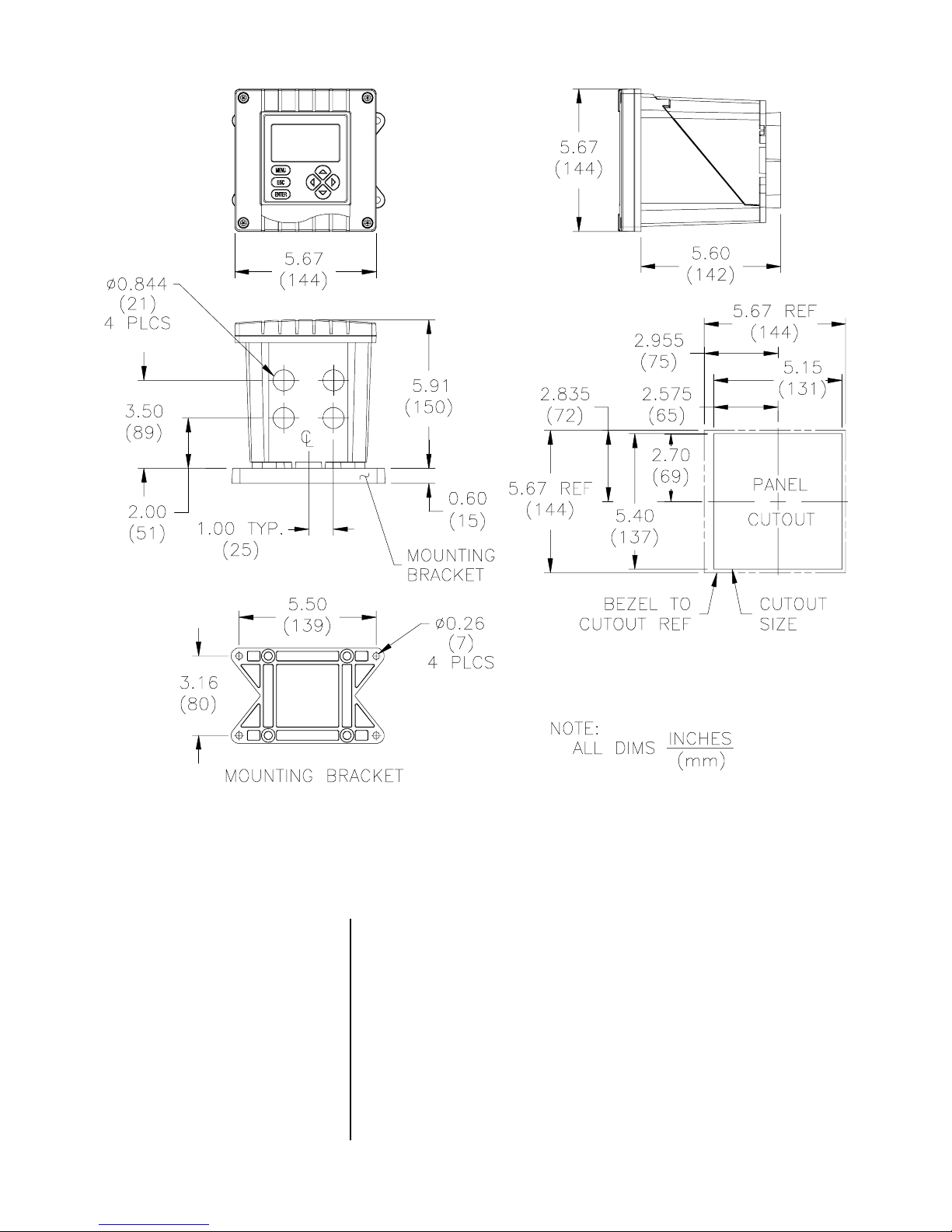
PART TW O - INSTALLATION SECTION 2 - MECHANICAL REQUIREMENTS
FIGURE 2-2 Analyzer Installation Dimensions Details
2.3 Conduit Hole
Requirements
☞
Rev. 1-201 Model F53 Flow Monitor/Totalizer (universal-mount 1/2 DIN)
Recommendation:
inch, grounded metal conduits. If using only shielded cables, appropriate strain reliefs or cable grips are required.
(GLI offers accessory cable grips, part number 3H1091, and
watertight locknuts, part number 3H1230, for cable entries.)
Seal unused cable entry holes with appropriate plugs.
NOTE:
Use NEMA 4-rated fittings and plugs to maintain the
Run all wiring to the analyzer in 1/2-
watertight integrity of the NEMA 4X enclosure.
23

PART TW O - INSTALLATION SECTION 3 - ELECTRICAL CONNECTIONS
ECTION
S
ELECTRICAL CONNECTIONS
To access terminals for electrical connections, open the lefthinged enclosure door by unscrewing the four fasteners.
Figure 2-3 shows the terminal arrangement and their designations.
3
☞
☞
NOTE: All terminals are suitable for single wires up to 14
AWG (2.5 mm2).
Wiring Tip!
electromagnetic compatibility requirements, follow these
general wiring guidelines:
1. Keep all cable shields as short as possible inside
the analyzer, and connect them to the ground terminals provided. Performance may be improved by
using cable glands that enable the shield to directly
contact the analyzer chassis.
2. Use Steward ferrite 28 B0590-000 or equivalent on
the sensor cable -- two turns required.
3. In harsh conducted RF conditions, connect the earth
ground of the analyzer to a local, known earth
ground source.
To comply with European Community (CE)
☞
Model F53 Flow Monitor/Totalizer (universal-mount 1/2 DIN) Rev. 1-201
NOTE: For easier wiring, connect line power and relay out-
puts through the back conduit holes before
connecting the sensors, analog outputs, and pulse
outputs through the front holes.
24

PART TW O - INSTALLATION SECTION 3 - ELECTRICAL CONNECTIONS
FLOW ANALYZER
5
HART
OUT 1
21 43
OUT 2
4-20 mA
TB2
TX
RELAY A
COMNC
21
876 111091615141312 191817
RX
RS-232
TTL
RELAY B
NO
COMNC COMNCNO
POWER
90-130 VAC
180-260 VAC
10VA 50/60 Hz
RELAY C
8674533411 12910
RELAY D
COMNCNO
F1F
T
NO
230
100mA80mA
FIGURE 2-3 Analyzer Terminal Block Designations
20
2221
2423
TB1
NC
NC
NO
NO
COM
COM
N115
TB3
23
2
T
3.1 Flow Sensor(s)
☞
☞
The analyzer can be used with up to four GLI impeller or
non-GLI flow sensors in any combination. Non-GLI sensors
must have a 0-2000 Hz. output such as provided by a paddle wheel, turbine, vortex, and other flow sensors.
Wiring Tip!
Route each sensor cable in 1/2-inch,
grounded metal conduit to protect it from moisture,
electrical noise, and mechanical damage.
For installations where the distance between sensor and
analyzer exceeds the sensor cable length, indirectly
connect the sensor to the analyzer using a junction box
and interconnect cable.
NOTE:
Do not route the sensor cable in any conduit containing AC or DC power wiring (“electrical noise”
may interfere with the sensor signal).
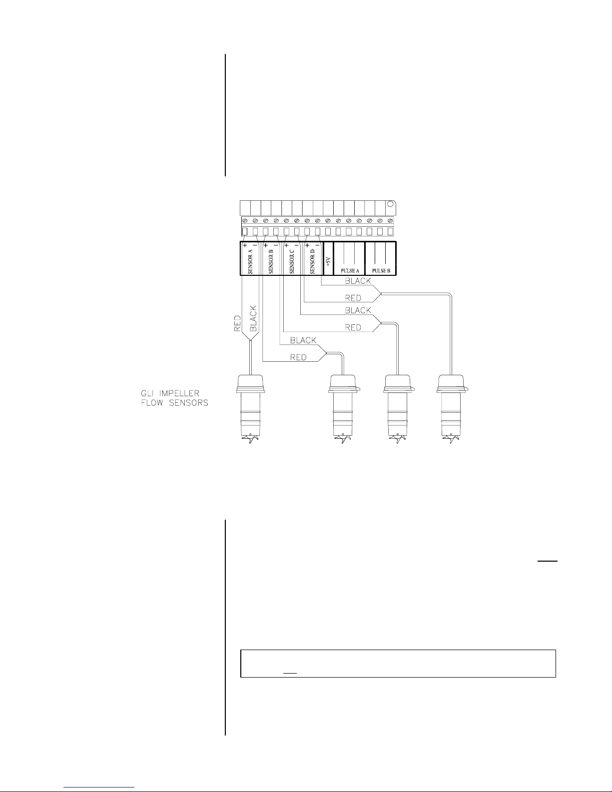
Refer to Figure 2-4 and connect the Sensor A cable (or interconnect) wires to Terminals 10 and 11 on TB1, matching
polarity as indicated. Connect additional sensors to their
respectively-marked terminals.
Rev. 1-201 Model F53 Flow Monitor/Totalizer (universal-mount 1/2 DIN)
25
PART TW O - INSTALLATION SECTION 3 - ELECTRICAL CONNECTIONS
☞
NOTE: For best immunity to electromagnetic interference,
connect each sensor cable’s shield wire to the
grounding strip at bottom of case (5 open holes).
For non-GLI sensors that require up to +5 VDC
power, connect its additional wire to Terminal 18 on
TB1. A separate external power supply is required
for higher voltages.
10 11 12 13 14 15 16 17 18 19 20
21 22
23 24
TB1
NO
NC
NO
COM
NC
COM
3.2 Analog Outputs
FIGURE 2-4 Connecting Flow Sensor(s)
Two isolated analog outputs (1 and 2) are provided. Each
output can be set to be 0-20 mA or 4-20 mA and, depending
on the number of sensors used, assigned to represent one
of these measurements:
•
Sensor A flow rate
•
Sensor B flow rate
•
Sensor C flow rate
•
Sensor D flow rate
•
Sensor A volume
*An analog output can only represent the calculated measurement when two sensors
are used and the analyzer has been correctly configured for CALCULATION.
•
Sensor B volume
•
Sensor C volume
•
Sensor D volume
•
Calculated measurement*
The outputs are isolated from the inputs and earth
ground, but not from each other.
For output configuration
details, see PART THREE, Section 4.4.
Model F53 Flow Monitor/Totalizer (universal-mount 1/2 DIN) Rev. 1-201
26

PART TW O - INSTALLATION SECTION 3 - ELECTRICAL CONNECTIONS
☞
☞
Wiring Tip!
cable for connecting the analog outputs. To protect the
output signals from EMI/RFI, connect cable shields to
the grounding strip at bottom of case (5 open holes).
Each 0/4-20 mA output can drive a load of up to 600 ohms.
Output 1:
•
matching polarity as indicated.
Output 2:
•
matching polarity as indicated.
NOTE: When using the HART communication option, a
Use high quality, shielded instrumentation
Connect the load to Terminals 2 and 3 on TB1,
Connect the load to Terminals 4 and 5 on TB1,
digital signal is encoded onto the 4-20 mA analog
Output 1 signal. In a HART SINGLE MODE wiring
configuration, Output 1 remains available for normal
use. However, in a HART MULTI-DROP wiring configuration, Output 1 becomes dedicated to that
function and cannot be used. See PART THREE,
Section 8 for more HART communication information.
3.3 Relay Outputs
The analyzer is equipped with four electromechanical relays.
For relay setup details, see PART THREE, Section 4.5.
CAUTION:
DO NOT EXCEED THE CONTACT RATING FOR
EACH RELAY (5A 115/230 VAC). WHEN SWITCHING
LARGER CURRENTS, USE AN AUXILIARY RELAY
SWITCHED BY THE ANALYZER RELAY TO EXTEND
ANALYZER RELAY LIFE. WHEN USING RELAY
OUTPUTS, MAKE SURE THAT LINE POWER WIRING
CAN ADEQUATELY CONDUCT THE CURRENT
DRAW OF THE SWITCHED LOAD(S).
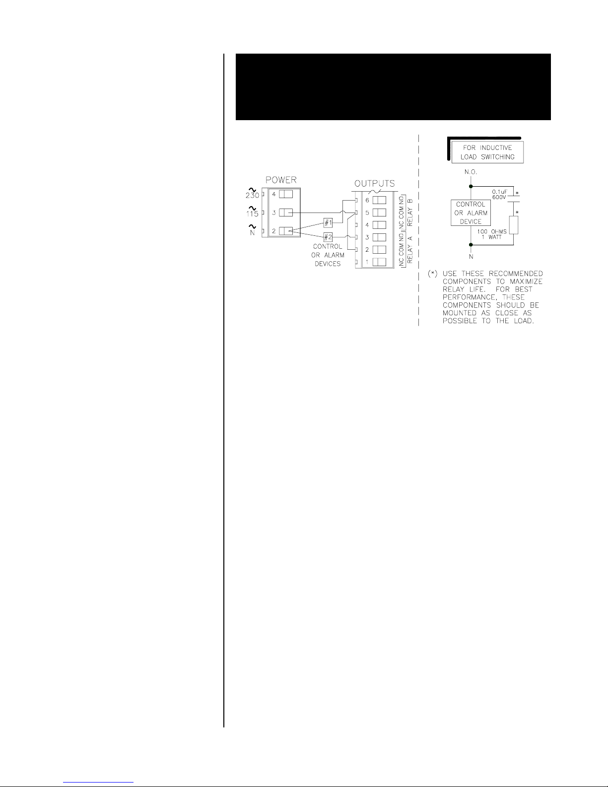
Four sets of SPDT relay outputs (Relays A, B, C, and D) are
provided at Terminals 1 through 12 on TB2.
puts are not powered.
analyzer may also be used to power control/alarm devices
with these relay contacts. See Figure 2-5 for a general wiring arrangement. Always check control wiring to insure that
line power will not be shorted by the relay switching action,
and that wiring conforms to local codes.
The line power used to power the
The relay out-
Rev. 1-201 Model F53 Flow Monitor/Totalizer (universal-mount 1/2 DIN)
27
PART TW O - INSTALLATION SECTION 3 - ELECTRICAL CONNECTIONS
WARNING:
MAKE SURE LINE POWER IS NOT PRESENT WHILE
CONNECTING WIRES TO TB2 RELAY TERMINALS.
3.4 Pulsed Outputs
(contact closure)
3.5 Closed Contact
TTL Input
FIGURE 2-5
Connecting Control/Alarm Device(s) To Electromechanical Relay(s)
Two sets of SPDT pulse contact closure outputs (A and B)
are provided at Terminals 19 through 24 on TB1. Connect
remote devices such as counters or pumps to appropriate
terminals. For pulsed output configuration details, see
PART THREE, Section 4.6.
The closed contact input feature of the analyzer enables
you to conveniently:
•
Hold the analog outputs at their last measured values.
•
Hold CONTROL and ALARM relays in their present
“on/off” states.
☞
Model F53 Flow Monitor/Totalizer (universal-mount 1/2 DIN) Rev. 1-201
To initiate these actions, momentarily connect TTL Terminals 8 and 9 on TB1, either locally or remotely.
NOTE:
During calibration, the selected output state
(“HOLD,” “XFER” or “ACTIVE”) overrides the TTL
input hold feature.
28
PART TW O - INSTALLATION SECTION 3 - ELECTRICAL CONNECTIONS
3.6 Line Power
☞
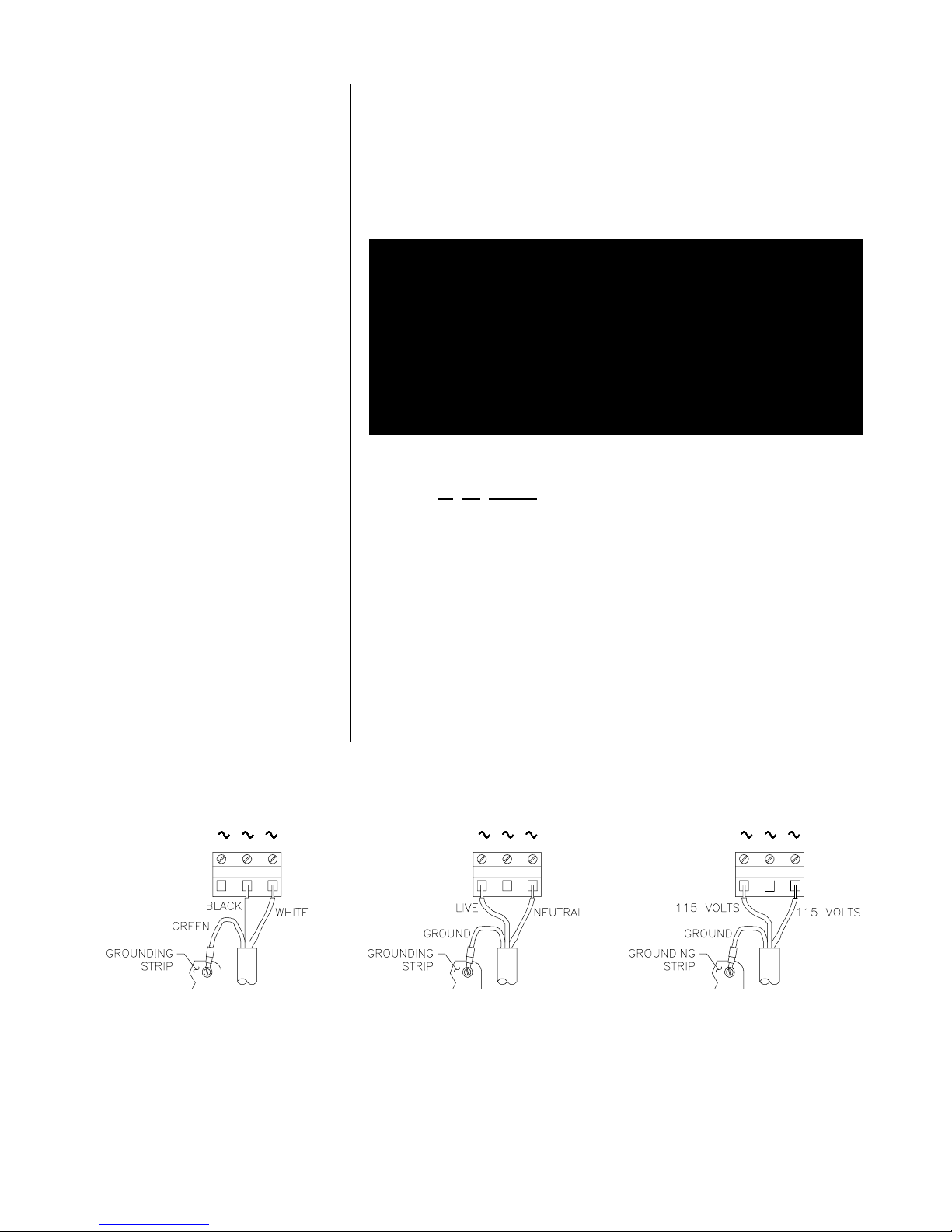
Refer to Figure 2-6, 2-7 or 2-8 and connect line power to
appropriate terminals on TB3 using the standard three-wire
connection arrangement.
form to local codes
Use wiring practices which con-
(example: National Electric Code
Handbook in the U.S.A.).
WARNING:
REMOVE LINE POWER WHILE CONNECTING LINE
POWER WIRES TO THE TB3 TERMINALS. ALSO,
USE ONLY THE STANDARD THREE-WIRE CONNECTION ARRANGEMENT FOR SINGLE-PHASE LINE
POWER TO PREVENT AN UNSAFE CONDITION, AND
TO ENSURE PROPER ANALYZER OPERATION.
NOTE: In all cases, connect the line power cable ground
wire (usually green) to the grounding strip at bottom
of case (5 open holes).
☞
115230 N
342
FIGURE 2-6
Connecting 115 Volt Single Phase
Line Power (90-130 VAC)
The “115” and “230” voltage circuits are protected with internal, board-mounted slow-blow fuses.
NOTE: For 230 volt split phase line power, be sure to con-
form to local codes with regard to fusing the 115
volt line connected to the “N” terminal.
230 115 N
234
FIGURE 2-7
Connecting 230 Volt Single Phase
Line Power (180-260 VAC)
FIGURE 2-8
Connecting 230 Volt Split Phase
Line Power (180-260 VAC)
N115230
234
Rev. 1-201 Model F53 Flow Monitor/Totalizer (universal-mount 1/2 DIN)
29
 Loading...