

GLI International C53 Operating Instructions Manual

OPERATING INSTRUCTION MANUAL
Model C53
Conductivity Analyzer
(Universal-mount 1/2 DIN style;
selectable for conductivity, resistivity, TDS,
and calculated Sensor A and B measurement)
Worldwide Headquarters and Sales:
GLI International, Inc.
9020 West Dean Road
Milwaukee, Wisconsin 53224
U.S.A.
In the interest of improving and updating its equipment, GLI reserves the right to alter specifications to equipment at any time.
Rev. 5-1000 Model C53 Conductivity Analyzer (universal-mount 1/2 DIN)
Phone:
Fax:
E-mail:
Web:
Represented By:
[414] 355-3601
[414] 355-8346
info@gliint.com
www.gliint.com
Viridor Instrumentation
A company
1

Model C53 Conductivity Analyzer (universal-mount 1/2 DIN) Rev. 5-1000
2

IMPORTANT SAFETY INFORMATION
This analyzer is compliant with safety standards as outlined in:
FMRC Class Numbers 3600, 3611, and 3810 (U.S.A.)
CSA C22.2 No. 142 and C22.2 No. 213 (Canada)
EN 61010-1 (European Community)
Please read and observe the following:
•
Opening the analyzer door exposes you to line power voltage, if present, at terminals on TB2 and TB3
inside the enclosure. This may be hazardous. Always remove line power before entering this area in
the analyzer. However, the analyzer door assembly contains only low voltage and is completely safe
to handle.
•
Wiring or repairs should only be performed by qualified personnel and only to an unpowered analyzer.
•
Whenever it appears that analyzer safety is questionable, disable the analyzer to ensure against any
unintended operation. For example, an unsafe condition is likely when:
1) The analyzer appears visibly damaged.
2) The analyzer fails to operate properly or provide the intended measurements.
3) The analyzer has been stored for long periods at temperatures above 158°F (70°C).
•
This analyzer must be installed by specially trained personnel in accordance with relevant local codes
and instructions contained in this operating instruction manual. Observe the analyzer’s technical
specifications and input ratings. If one line of the line power mains is not neutral, use a double-pole
mains switch to disconnect the analyzer.
HELPFUL IDENTIFIERS
In addition to information on installation and operation, this instruction manual may contain
WARNINGS pertaining to user safety, CAUTIONS regarding possible instrument malfunction, and
NOTES on important, useful operating guidelines.
WARNING:
A WARNING LOOKS LIKE THIS. IT WARNS YOU OF THE POTENTIAL
FOR PERSONAL INJURY.
CAUTION:
A CAUTION LOOKS LIKE THIS. IT ALERTS YOU TO POSSIBLE
INSTRUMENT MALFUNCTION OR DAMAGE.
☞
NOTE: A note looks like this. It alerts you to important, useful operating
information.
Rev. 5-1000 Model C53 Conductivity Analyzer (universal-mount 1/2 DIN)
3
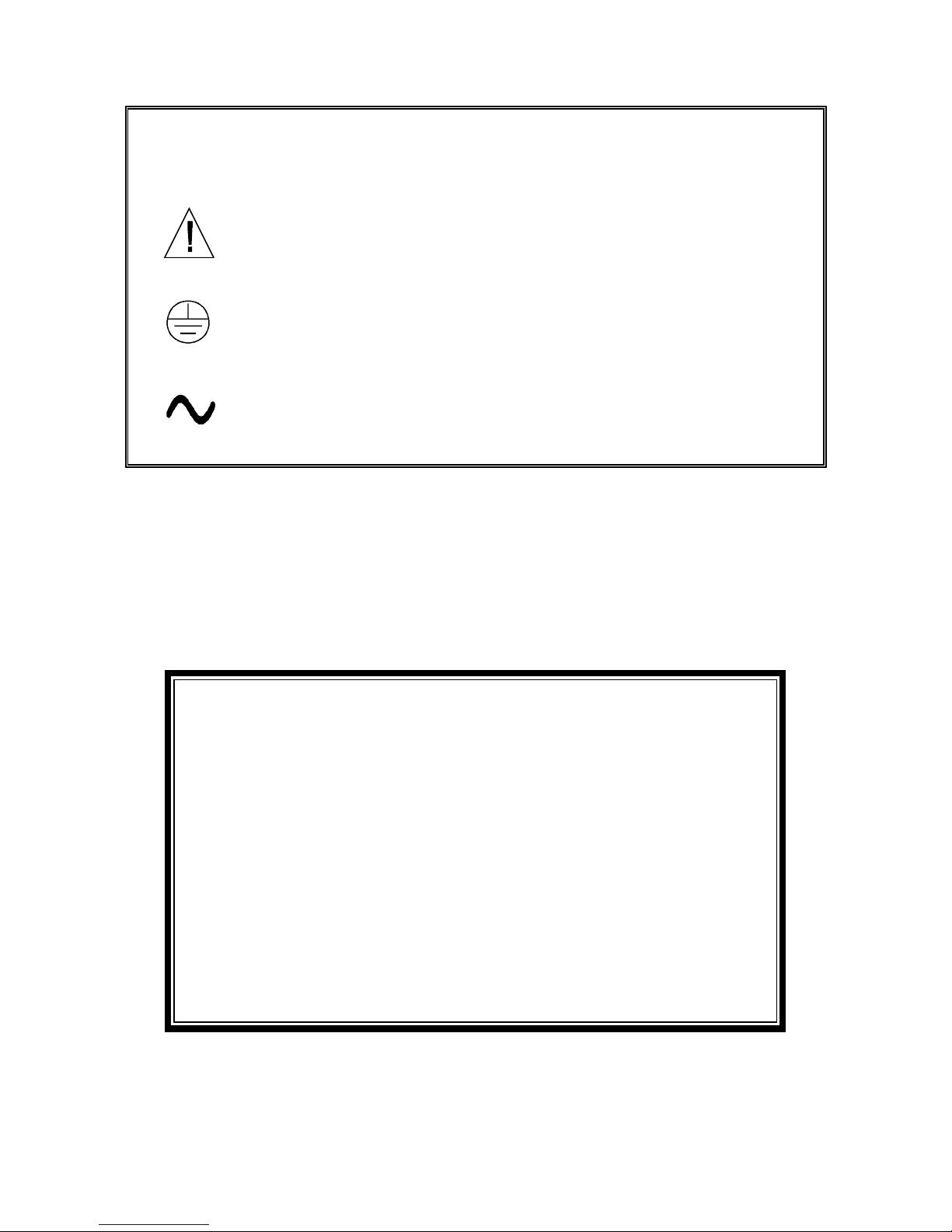
Definition of Equipment Symbols
This symbol
means CAUTION
and alerts you to possible danger or
instrument malfunction. Refer to this manual before proceeding.
This symbol
means that this is a protective ground terminal
alerts you to connect an earth ground to it.
This symbol
means that there is alternating current present
alerts you to be careful.
and
and
WARRANTY
GLI International, Inc. warrants the Model C53 to be free from defects in material
or workmanship for a period of 2 years (24 months) from the date of shipment of
this product from our facility. A warranty claim will not be honored if defects are
not reported within the warranty period, or if GLI International determines that
defects or damages are due to normal wear, misapplication, lack of maintenance, abuse, improper installation, alteration, or abnormal conditions. GLI
International’s obligation under this warranty shall be limited to, at its option, replacement or repair of this product. The product must be returned to GLI
International, freight prepaid, for examination. The product must be thoroughly
cleaned and any process chemicals removed before it will be accepted for replacement or repair. GLI International’s liability shall not exceed the cost of the
product. Under no circumstances will GLI International be liable for any incidental or consequential damages, whether to person or property. GLI International
will not be liable for any other loss, damage or expense of any kind, including
loss of profits, resulting from the installation, use, or inability to use this product.
Model C53 Conductivity Analyzer (universal-mount 1/2 DIN) Rev. 5-1000
4

CONDENSED OPERATING INSTRUCTIONS
This manual contains details for all operating aspects of the instrument. The following condensed instructions are provided to assist you in getting the instrument started up and operating as quickly as
possible.
tion.
These condensed instructions only pertain to basic conductivity measurement
To measure resistivity, TDS or a calculated Sensor A and B measurement, or to use specific
features of the instrument, refer to the appropriate sections in this manual for instructions.
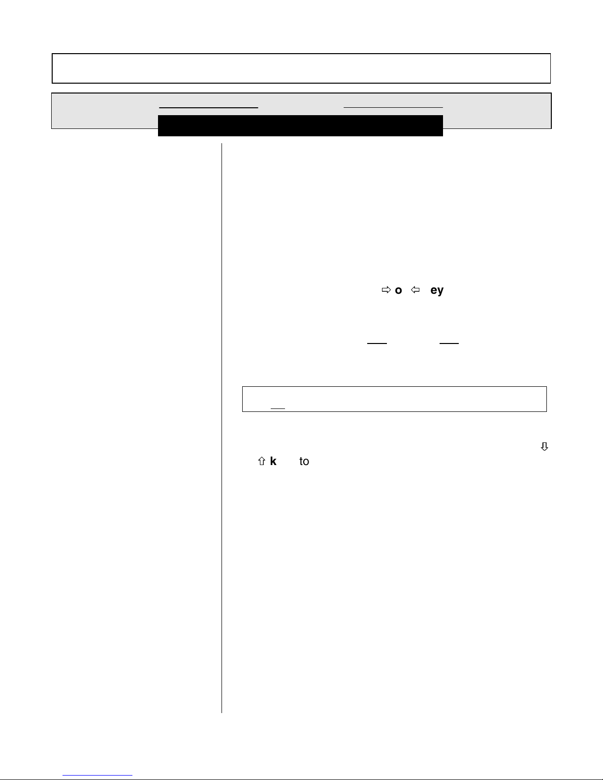
A. CONNECTING SENSOR(S)/CONFIGURING TEMPERATURE ELEMENT(S)
1. After properly mounting the analyzer (PART TWO, Section 2), connect the GLI enhanced performance contacting conductivity sensor(s), matching wire colors to terminals as indicated:
Sensor A
Wire Colors
Clear w/black (outer shield)Grounding strip lug Terminal #17 on TB1
Blue Terminal #18 on TB1 Terminal #18 on TB1
White Terminal #19 on TB1 Terminal #19 on TB1
Clear (inner shield wire) Terminal #20 on TB1 Terminal #20 on TB1
Black Terminal #21 on TB1 Terminal #21 on TB1
Red Terminal #22 on TB1 Terminal #22 on TB1
Wire Colors
Clear w/black (outer shield)Grounding strip lug Terminal #11 on TB1
Blue Terminal #12 on TB1 Terminal #12 on TB1
White Terminal #13 on TB1 Terminal #13 on TB1
Clear (inner shield wire) Terminal #14 on TB1 Terminal #14 on TB1
Black Terminal #15 on TB1 Terminal #15 on TB1
Red Terminal #16 on TB1 Terminal #16 on TB1
Analyzers with
“B” Prefix Serial No.
Sensor B
Analyzers with
“B” Prefix Serial No.
Analyzers with
“A” or No Letter
Prefix Serial No.
Analyzers with
“A” or No Letter
Prefix Serial No.
opera-
2. The analyzer is factory-set for use with the Pt 1000 ohm temperature element built into GLI enhanced performance contacting conductivity sensors. When using a sensor brand with a different
temperature element, or for fixed MANUAL temperature compensation, you must change the
temperature element type (see PART THREE, Section 4.2, subheading “Select TEMP
ELEMENT Type”).
B. CONNECTING LINE POWER
Important:
Follow the instructions in PART TWO, Section 3.5 to connect line power to the analyzer.
C. ADJUSTING DISPLAY CONTRAST
Ambient lighting conditions may make it necessary to adjust display contrast to improve visibility.
With the MEASURE screen displayed, press and hold
×
Ø
×
or
until attaining the desired contrast.
key
Ø
D. CALIBRATING THE ANALYZER
The analyzer must be calibrated so that measured values will correspond to actual process values. It
can be traditionally “wet” calibrated. However, since measured conductivity is greatly affected by
small changes in temperature, GLI strongly recommends
measuring accuracy of conductivity and temperature. Besides, DRY-CAL is actually a normal part of
Rev. 5-1000 Model C53 Conductivity Analyzer (universal-mount 1/2 DIN)
ENTER key
the
and simultaneously press the
using its DRY-CAL method for highest
5
CONDENSED OPERATING INSTRUCTIONS
D. CALIBRATING THE ANALYZER -- (continued)
configuring the sensor characteristics during initial startup, and
conductivity reference solutions.
This method also automatically sets the analyzer measuring
DRY-CAL eliminates the need for
range to match the inherent range of the sensor’s cell constant. For more details about the benefits
of DRY-CAL, refer to the “Calibration Tip!” in PART THREE, Section 5.1.
NOTE: DRY-CAL eliminates the need for periodic re-calibration! The only requirement, depending
on the application, may be to periodically clean the sensor. Only when the sensor is replaced is it necessary to perform a new DRY-CAL calibration.
Calibration Tip!
Each contacting conductivity sensor has a unique zero point and offset. Consequently, when calibrating a sensor for the first time, always zero it according to step 1. Zeroing
provides the best possible measuring accuracy, and eliminates any discrepancy between Sensor A
and B measurement channels.
DRY-CAL calibration, routinely attained while configuring the analyzer for sensor characteristics, requires entry of the sensor’s GLI-certified “CELL K” value and temperature “T FACTOR” which are
unique to each sensor. When using two sensors, enter each unique set of values using respective
sensor menu screens.
1. Zero the sensor if it is being calibrated for
the first time. If not, disregard this step and perform
steps 2 through 14.
Zeroing Tip!
ENTER key
press
If at any time during zeroing, the “ZERO: CONFIRM FAILURE?” screen appears,
×
Ø
or
to confirm. Then, use the
×
key
Ø
to select between “CAL: EXIT” or
“CAL: REPEAT” and do one of the following:
•
With the “ZERO? (CAL: EXIT)” screen selected, press
CONFIRM ACTIVE?” screen appears, press
ENTER key
ENTER key
. After the “ZERO:
to return the analog outputs and
relays to their activ e states (MEASURE screen appears).
•
With the “ZERO?: (CAL: REPEAT)” screen selected, press
ENTER key
to repeat zeroing.
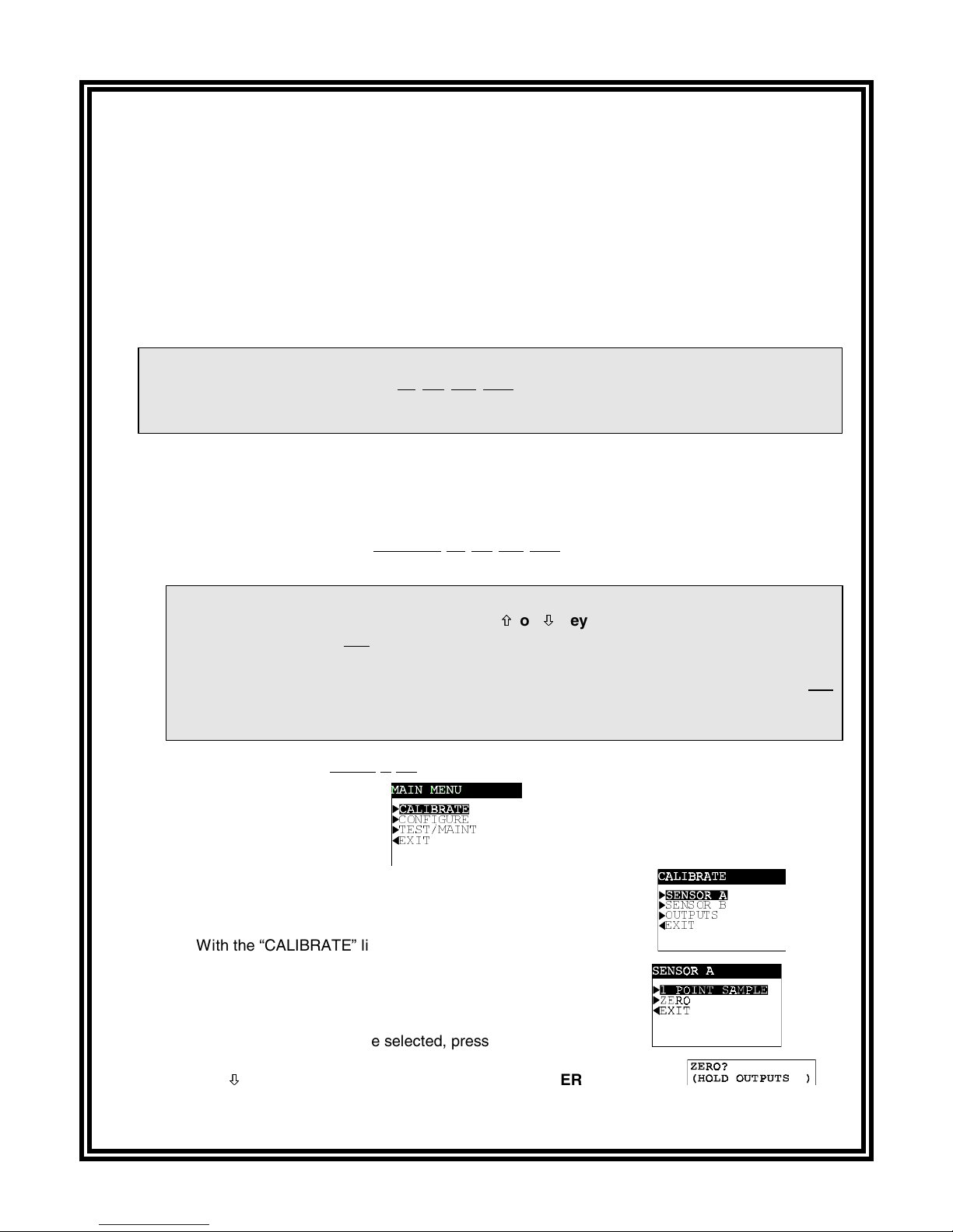
A. Make sure that the sensor is dry before zeroing.
B. Press
MENU key
to display
C. With the “CALIBRATE” line selected, press
D. With the “SENSOR A” line selected, press
E. Use
Model C53 Conductivity Analyzer (universal-mount 1/2 DIN) Rev. 5-1000
Ø
to select the “ZERO” line, and press
key
Ø
&21),*85(
7(670$,17
(;,7
.
ENTER key
ENTER key
ENTER key
(continued on next page)
6
to display
to display
to display
6(1625 %
2873876
(;,7
.
.
.
CONDENSED OPERATING INSTRUCTIONS
D. CALIBRATING THE ANALYZER -- (continued)
F. Press
ENTER key
to “hold” the analog outputs and relays at their present states during ze-
roing. (Outputs can also be transferred to present values or allowed to remain active.)
G. With the “ZERO: IN DRY AIR?” screen displayed and the dry sensor held
ENTER key
H. After the “ZERO: CONFIRM ZERO OK?” screen appears, press
I. After the “ZERO: CONFIRM ACTIVE?” screen appears, press
to start the automatic zeroing.
ENTER key
ENTER key
analog outputs and relays to their active states (MEASURE screen appears).
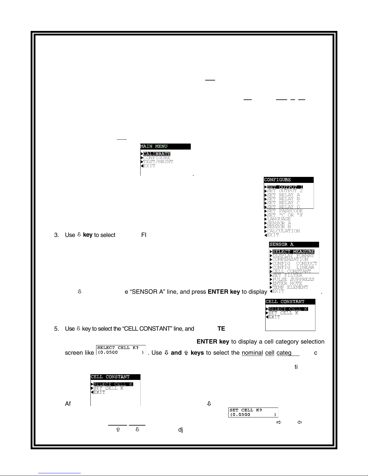
&21),*85(
7(670$,17
(;,7
2. Press
3. Use
MENU key
Ø
key
Ø
to select the “CONFIGURE” line, and press
to display
.
ENTER key
to display
in air, press
to end zeroing.
to return the
6(7 287387
6(7 5(/$< $
6(7 5(/$< %
6(7 5(/$< &
6(7 5(/$< '
6(7 3$66&2'(
6(7&25)
/$1*8$*(
6(1625 $
6(1625 %
&$/&8/$7,21
(;,7
.
',63/$< )250$7
&203(16$7,21
&21),* &21'8&7
&21),* /,1($5
&(// &2167$17
6(7 ),/7(5
38/6( 68335(66
(17(5 127(
7(03 (/(0(17
4. Use
5. Use
Ø
to select the “SENSOR A” line, and press
key
Ø
Ø
key to select the “CELL CONSTANT” line, and press
Ø
6. With the “SELECT CELL K” line selected, press
screen like . Use
Ø
Ø
and
×
keys
×
ENTER key
ENTER key
ENTER key
to display
to display
to display a cell category selection
to select the nominal cell category that cor-
(;,7
responds to the sensor’s GLI-certified “CELL K” value shown on a label attached to its cable or to
the inside cover of its optional junction box. Then press
7. After the
press
ENTER key
to display a “CELL K” value screen like
played value to exactly match
coarse adjust, and
×
×
and
screen re-appears, use
the sensor’s GLI-certified “CELL K” value. (Use
Ø
Ø
to fine adjust.) Then press
keys
(continued on next page.)
ENTER key
Ø
to select the “SET CELL K” line and
key
Ø
ENTER key
to enter the selection.
. Adjust the dis-
Ö
Ö
and
Õ
Õ
to enter the value.
keys
.
.
to
Rev. 5-1000 Model C53 Conductivity Analyzer (universal-mount 1/2 DIN)
7
CONDENSED OPERATING INSTRUCTIONS
D. CALIBRATING THE ANALYZER -- (continued)
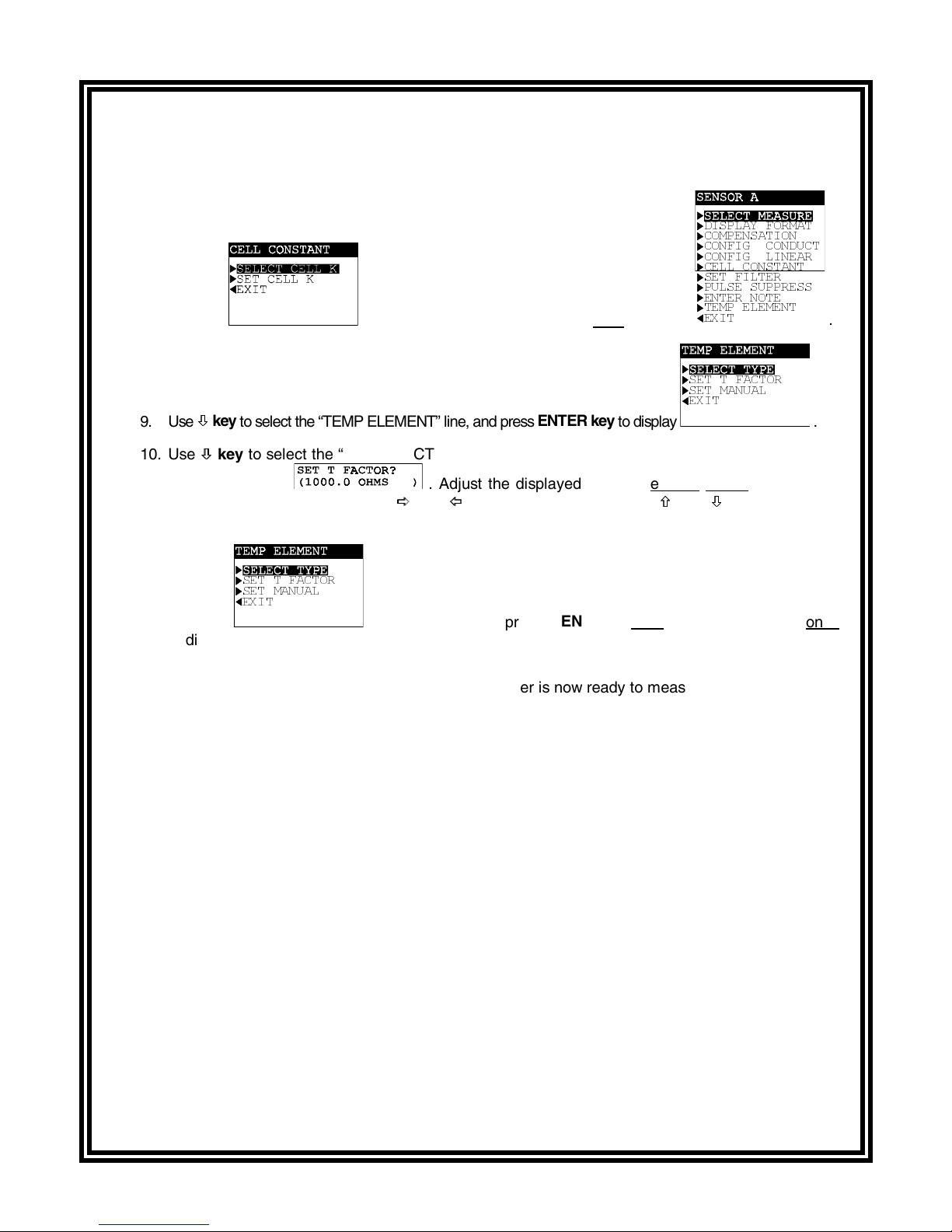
8. After the
Ø
key
9. Use
10. Use
Ø
to select the “TEMP ELEMENT” line, and press
Ø
key
Ø
to select the “SET T FACTOR” line, and press
value screen like . Adjust the displayed value to exactly match the sensor’s
GLI-certified “T FACTOR.” (Use
just.) Then press
ENTER key
screen re-appears, press
Ö
Ö
and
Õ
Õ
keys
to enter the value.
ESC key
ENTER key
once to display
to display
ENTER key
to coarse adjust, and
',63/$< )250$7
&203(16$7,21
&21),* &21'8&7
&21),* /,1($5
&(// &2167$17
6(7 ),/7(5
38/6( 68335(66
(17(5 127(
7(03 (/(0(17
(;,7
6(7 7 )$&725
6(7 0$18$/
(;,7
.
.
to display a “T FACTOR”
×
×
and
Ø
keys
Ø
to fine ad-
6(7 7 )$&725
6(7 0$18$/
(;,7
11. After the
screen re-appears, press
MENU key
once and then
ESC key
to display the MEASURE screen.
This completes GLI’s DRY-CAL calibration. The analyzer is now ready to measure conductivity.
To change the display format of the MEASURE screen (for example, from 0-2000 µS/cm to 0.000-2.000
mS/cm), refer to PART THREE, Section 4.2, subheading “Select DISPLAY FORMAT.”
NOTE: If the values you intend to measure are above the analyzer’s set measuring range (not its
selected display format), use a different sensor that has the appropriate nominal cell constant. For a listing of sensor cell constants and their inherent measuring ranges, see Table A
in PART THREE, Section 4.2, subheading “Select DISPLAY FORMAT.”
E. COMPLETING ANALYZER CONFIGURATION
To further configure the analyzer to your application requirements, use the appropriate CONFIGURE
screens to make selections and “key in” values. Refer to PART THREE, Section 4 for complete configuration details.
once
Model C53 Conductivity Analyzer (universal-mount 1/2 DIN) Rev. 5-1000
8
TABLE OF CONTENTS
PART ONE - INTRODUCTION
SECTION 1 GENERAL INFORMATION
1.1 Capability Highlights ........................................................................15-17
1.2 Modular Construction ............................................................................17
1.3 Retained Configuration Values .............................................................17
1.4 Analyzer Serial Number ........................................................................17
1.5 EMI/RFI Immunity.................................................................................. 18
SECTION 2 SPECIFICATIONS
....................................................................................19-20
PART TWO - INSTALLATION
SECTION 1 UNPACKING
SECTION 2 MECHANICAL REQUIREMENTS
2.1 Location................................................................................................. 21
2.2 Mounting...........................................................................................21-23
2.3 Conduit Hole Requirements .................................................................. 23
SECTION 3 ELECTRICAL CONNECTIONS
3.1 GLI Enhanced Performance Contacting Conductivity Sensor(s)......24-26
3.2 Analog Outputs...................................................................................... 27
3.3 Relay Outputs........................................................................................ 28
3.4 Closed Contact Input............................................................................. 29
3.5 Line Power .......................................................................................29-30
.................................................................................................21
PART THREE - OPERATION
SECTION 1 USER INTERFACE
1.1 Display .............................................................................................31-32
1.2 Keypad .............................................................................................32-33
1.3 MEASURE Screen (normal display mode) .......................................33-34
SECTION 2 MENU STRUCTURE
2.1 Displaying Main Branch Selection Screen ............................................ 35
2.2 Displaying Top-level Menu Screens.................................................35-36
2.3 Displaying Submenu Screens ...............................................................36
2.4 Adjusting Edit/Selection Screen Values ................................................36
2.5 Entering (Storing) Edit/Selection Screen Values/Choices..................... 36
Rev. 5-1000 Model C53 Conductivity Analyzer (universal-mount 1/2 DIN)
9

TABLE OF CONTENTS (continued)
SECTION 3 DISPLAY CONTRAST VISIBILITY
SECTION 4 ANALYZER CONFIGURATION
4.1 Selecting LANGUAGE to Operate Analyzer..........................................37
4.2 Configuring Sensor (A and B) Characteristics:
SELECT MEASURE (conductivity, resistivity or TDS) ................38-39
Select DISPLAY FORMAT..........................................................39-40
Select Temperature COMPENSATION............................................40
CONFIG TDS Measurement
(not needed for other measurements) ........................................41
CONFIG LINEAR Temperature Compensation
(not needed for other compensation methods)......................42-43
SELECT CELL K (sensor’s GLI-certified “K” value) .........................43
SET FILTER Time............................................................................ 44
Select PULSE SUPPRESS (on/off)..................................................44
ENTER NOTE (top line of MEASURE screen) ..................................45
Select TEMP ELEMENT Type ....................................................45-46
SET T FACTOR (sensor’s GLI-certified “T” factor) .....................47-48
4.3 Configuring Calculated Sensor A and B Measurement:
SELECT MEASURE (none, % rejection, % passage,
ratio A/B, ratio B/A, difference A-B or difference B-A) ................48
Select DISPLAY FORMAT (only for ratio A/B or ratio B/A;
not needed for other calculated measurements) ........................49
4.4 SET °C OR °F (temperature display format) .........................................49
4.5 Configuring Analog Outputs (1 and 2):
SET PARAMETER (representation) ...........................................50-51
SET 0/4 mA and 20 mA VALUES (range expand) ........................... 51
SET TRANSFER Value (mA) ........................................................... 52
SET FILTER Time............................................................................ 52
Select SCALE 0 mA/4 mA (low endpoint) ........................................53
4.6 Configuring Relays (A, B, C, and D):
SET PARAMETER (representation) ...........................................53-54
SET FUNCTION Mode (alarm, control or status)........................54-55
SET TRANSFER Mode (relay on or off) ..........................................55
ACTIVATION (configuration values) ...........................................56-57
4.7 SET PASSCODE (feature enabling or disabled)...................................58
4.8 Configuration Setting Summary (ranges/choices and defaults) .......59-61
...............................................................37
SECTION 5 ANALYZER CALIBRATION
5.1 Things to Know About Calibration ....................................................62-63
5.2 Zero Procedure (first-time sensor calibration only) ..........................63-64
5.3 DRY-CAL Method (highly recommended):
SELECT CELL K (sensor’s GLI-certified “K” value) ....................64-65
SET T FACTOR (sensor’s GLI-certified “T” factor) .....................65-67
Model C53 Conductivity Analyzer (universal-mount 1/2 DIN) Rev. 5-1000
10

TABLE OF CONTENTS (continued)
5.4 1 POINT SAMPLE Method (wet calibration).....................................67-69
5.5 Analog Outputs (1 and 2) Calibration...............................................70-71
SECTION 6 TEST/MAINTENANCE
6.1 STATUS Checking (analyzer, sensors, and relays) .........................72-73
6.2 HOLD OUTPUTS ..................................................................................74
6.3 OVERFEED RESET (relay timers) ...................................................74-75
6.4 OUTPUT (1 and 2) Analog Test Signals ............................................... 75
6.5 RELAY (A, B, C, and D) Operating Test...........................................75-76
6.6 EPROM VERSION Checking ................................................................76
6.7 SELECT SIM Measurement ..................................................................77
6.8 SIM SENSOR Setting.......................................................................77-78
6.9 RESET DEFAULTS (configuration settings to factory-set values) .......78-79
SECTION 7 RELAY OVERFEED TIMER FEATURE
7.1 Why Use an Overfeed Timer................................................................. 80
7.2 Configuring Relay Overfeed Timers...................................................... 80
7.3 Overfeed Timer “Timeout” Operation .................................................... 80
7.4 Resetting Overfeed Timers ...................................................................80
7.5 Interactions with Other Analyzer Functions......................................80-81
SECTION 8 HART OPTION
8.1 Introduction ........................................................................................... 82
8.2 Analyzer Operating Modes for HART Network.................................83-84
8.3 SINGLE MODE (Point-to-Point) Wiring Arrangement ...........................84
8.4 MULTI-DROP Wiring Arrangement....................................................... 85
8.5 HART Preferences Setup:
Changing Polling Address ...............................................................86
Viewing Number of Required Preambles ....................................86-87
8.6 Device Preferences Setup:
Viewing Final Assembly Number ..................................................... 87
Viewing Model Number...............................................................87-88
Viewing Manufacturer ......................................................................88
Assigning a Tag ...............................................................................88
Assigning a Descriptor .....................................................................89
Assigning a Message....................................................................... 89
Assigning User-defined Date ......................................................89-90
Viewing Identification (ID) ................................................................90
Viewing Revisions............................................................................ 90
8.7 “Master Reset” Function........................................................................ 91
8.8 “Refresh” Function ................................................................................91
8.9 Protocol Command Set for PC Programming ........................................ 91
Rev. 5-1000 Model C53 Conductivity Analyzer (universal-mount 1/2 DIN)
11
TABLE OF CONTENTS (continued)
PART FOUR - SERVICE AND MAINTENANCE
SECTION 1 GENERAL INFORMATION
1.1 Inspecting Sensor Cable(s) ................................................................... 92
1.2 Replacing Fuse(s) ................................................................................. 92
1.3 Replacing Relays ..................................................................................92
SECTION 2 PRESERVING MEASUREMENT ACCURACY
2.1 Keeping Sensor(s) Clean ......................................................................93
2.2 Keeping Analyzer Calibrated................................................................. 93
2.3 Avoiding Electrical Interference............................................................. 93
SECTION 3 TROUBLESHOOTING
3.1 Ground Loops:
Determining if Ground Loop Exists ..................................................94
Finding Source of Ground Loop.......................................................95
3.2 Isolating Measuring System Problem:
Checking Electrical Connections .....................................................95
Verifying Sensor Operation..............................................................95
Verifying Analyzer Operation ......................................................95-96
Verifying Interconnect Cable Integrity .........................................96-97
SECTION 4 ANALYZER REPAIR/RETURN
4.1 Customer Assistance.............................................................................98
4.2 Repair/Return Policy .............................................................................98
PART FIVE - SPARE PARTS AND ACCESSORIES
......................................................................................................................99
Model C53 Conductivity Analyzer (universal-mount 1/2 DIN) Rev. 5-1000
12

TABLE OF CONTENTS (continued)
ILLUSTRATIONS
Figure 1-1
Figure 2-1
Figure 2-2
Figure 2-3
Figure 2-4
Figure 2-5
Figure 2-6
Figure 2-7
Figure 2-8
Figure 2-9
Figure 2-10
Figure 2-11
Figure 2-12
Figure 2-13
Figure 3-1
EMI/RFI Immunity Diagram ................................................................................................ 18
Analyzer Mounting Arrangements ....................................................................................... 22
Analyzer Installation Dimension Details .............................................................................. 23
Terminal Designations for Analyzers with “B” Prefix Serial Number .................................... 25
Terminal Designations for Analyzers with “A” or No Letter Prefix Serial Number................. 25
Connecting GLI Contacting Conductivity Sensor(s) to Analyzers
with “B” Prefix Serial Number......................................................................................... 26
Connecting GLI Contacting Conductivity Sensor(s) to Analyzers
with “A” or No Letter Prefix Serial Number ..................................................................... 26
Connecting Control/Alarm Device(s) to Electromechanical Relay(s) ................................... 28
Connecting 115 V Single Phase to Analyzers with “B” Prefix Serial Number....................... 30
Connecting 115 V Single Phase to Analyzers with “A” or No Letter Prefix Serial Number.... 30
Connecting 230 V Single Phase to Analyzers with “B” Prefix Serial Number....................... 30
Connecting 230 V Single Phase to Analyzers with “A” or No Letter Prefix Serial Number.... 30
Connecting 230 V Split Phase to Analyzers with “B” Prefix Serial Number.......................... 30
Connecting 230 V Split Phase to Analyzers with “A” or No Letter Prefix Serial Number ...... 30
Analyzer Keypad ................................................................................................................ 32
Figure 3-2
Figure 3-3
Figure 3-4
Table A
Table B
Table C
Table D
Table E
Table F
Location of Analyzer SINGLE MODE/MULTI-DROP Switch................................................ 84
HART SINGLE MODE (Point-to-Point) Wiring Arrangement (for single analyzer) ............... 84
HART MULTI-DROP Wiring Arrangement (for multiple analyzer network) .......................... 85
TABLES
Sensor Cell Constants and Measuring Ranges ................................................................... 39
Relay Configuration Settings .............................................................................................. 56
Analyzer Configuration Settings (Ranges/Choices and Defaults) ................................... 59-61
Conductivity Reference Solutions ....................................................................................... 68
Relay Overfeed Timer Interactions with Other Analyzer Functions...................................... 81
Full-scale Equivalent Test Resistance Values..................................................................... 96
Rev. 5-1000 Model C53 Conductivity Analyzer (universal-mount 1/2 DIN)
13

Model C53 Conductivity Analyzer (universal-mount 1/2 DIN) Rev. 5-1000
14
PART ONE - INTRODUCTION SECTION 1 - GENERAL INFORMATION
PART ONE - INTRODUCTION
ECTION
1.1 Capability Highlights
Sensor Input
S
GENERAL INFORMATION
The analyzer has two independent sensor inputs for monitoring two measurement points. Each input can accept a
GLI Model 3400-series enhanced performance contacting
conductivity sensor (or another brand sensor with Pt 1000
RTD or Pt 100 RTD temperature compensator element).
1
MEASURE Screens
The MEASURE screen (normal display mode) can provide
different readouts of measured data. With the MEASURE
ÖÖ or
screen displayed, press the
1. Measured Sensor A value (conductivity, resistivity or TDS).
2. Measured Sensor B value (conductivity, resistivity or TDS).
3. Measured Sensor A and B values and temperatures.
4. *Calculated Sensor A and B measurement (% reject,
% pass, ratio A/B, ratio B/A, diff. A-B, or diff. B-A).
*The calculated measurement can only be displayed when two sensors are
used and the analyzer has been correctly configured for CALCULATION.
The bottom auxiliary display line on the MEASURE screen,
shown in reverse video, can be changed by pressing the
and
×× keys to show these measurements:
• Measured Sensor A temperature (°C or °F).
• Measured Sensor B temperature (°C or °F).
• Analog Output 1 value (mA).
• Analog Output 2 value (mA).
ÕÕ key to show:
Ø
Ø
Passcode-protected
Access
Calibration Methods
Rev. 5-1000 Model C53 Conductivity Analyzer (universal-mount 1/2 DIN)
For security, you can enable a passcode feature to restrict
access to configuration and calibration settings to authorized
personnel only. See PART THREE, Section 4.7 for details.
It is highly recommended to calibrate the analyzer using GLI’s
DRY-CAL method, which is simple to do and eliminates the
need to prepare a reference solution. However, the analyzer
can be traditionally “wet” calibrated. For calibration details, refer to PART THREE, Sections 5.2 and 5.3 or 5.4. Each analog
output mA value can also be calibrated (Section 5.5).
15
PART ONE - INTRODUCTION SECTION 1 - GENERAL INFORMATION
Analog Outputs
The analyzer provides two isolated analog outputs (1 and
2). Each output can be set to be 0-20 mA or 4-20 mA, and
assigned to represent one of the following:
•
Measured Sensor A conductivity, resistivity or TDS.
•
Measured Sensor A temperature.
•
Measured Sensor B conductivity, resistivity or TDS.
•
Measured Sensor B temperature.
•
*Calculated Sensor A and B measurement (% reject,
% pass, ratio A/B, ratio B/A, diff. A-B, or diff. B-A).
*An analog output can only represent the calculated measurement when
two sensors are used and the analyzer has been correctly configured for
CALCULATION.
Parameter (or calculated measurement) values can be entered to define the endpoints at which the minimum and
maximum analog output values are desired (range expand).
For analog output setup details, see PART THREE, Section
4.5.
During calibration, both analog outputs can be selected to:
Relays
•
Hold their present values (HOLD OUTPUTS)
•
Transfer to preset values to operate control elements by an
amount corresponding to those values (XFER OUTPUTS)
•
Remain active to respond to the measured value
(ACTIVE OUTPUTS).
The analyzer may have up to four electromechanical relays,
all with SPDT contacts. Each relay can be set to function as
a CONTROL, ALARM or STATUS relay. CONTROL and
ALARM relays can be assigned to be driven by one of these:
•
Measured Sensor A conductivity, resistivity or TDS.
•
Measured Sensor A temperature.
•
Measured Sensor B conductivity, resistivity or TDS.
•
Measured Sensor B temperature.
•
*Calculated Sensor A and B measurement (% reject,
% pass, ratio A/B, ratio B/A, diff. A-B, or diff. B-A).
☞
Model C53 Conductivity Analyzer (universal-mount 1/2 DIN) Rev. 5-1000
*A relay can only be driven by the calculated measurement when two sensors
are used and the analyzer has been correctly configured for CALCULATION.
NOTE: When a relay is set to function as a STATUS relay,
it is no longer configurable. Instead, it becomes a
16

PART ONE - INTRODUCTION SECTION 1 - GENERAL INFORMATION
dedicated system diagnostic-only alarm relay that
automatically energizes when the “WARNING
CHECK STATUS” message flashes on the
MEASURE screen. This occurs when the analyzer
detects a “fail” diagnostic condition. See PART
THREE, Section 6.1 for more details.
Except for STATUS relays, during calibration the relay
on/off states are affected in the same way as the analog
outputs by the “(HOLD/XFER/ACTIVE) OUTPUTS” screen
selection. These relays are also held at their present on/off
states, transferred to desired preset on/off states, or remain
active to respond to measured values.
Refer to PART THREE, Section 4.6 for relay setup details.
1.2 Modular Construction
1.3 Retained
Configuration Values
The modular construction of the analyzer simplifies field
servicing and provides electrical safety. The front door/
keypad assembly uses voltages no greater than 24 VDC,
and is completely safe to handle.
Opening the analyzer door accesses terminals inside the
enclosure for electrical connections. Line power must be
connected to specifically designated terminals on TB3.
WARNING:
REMOVE LINE POWER BEFORE NEARING THIS AREA
TO AVOID ELECTRICAL SHOCK.
All user-entered configuration values are retained indefinitely, even if power is lost or turned off. The non-volatile
analyzer memory does not require battery backup.
1.4 Analyzer
Serial Number
Rev. 5-1000 Model C53 Conductivity Analyzer (universal-mount 1/2 DIN)
A label with the analyzer model number, serial number,
build date, and other items is affixed to the top of the enclosure.
17
PART ONE - INTRODUCTION SECTION 1 - GENERAL INFORMATION
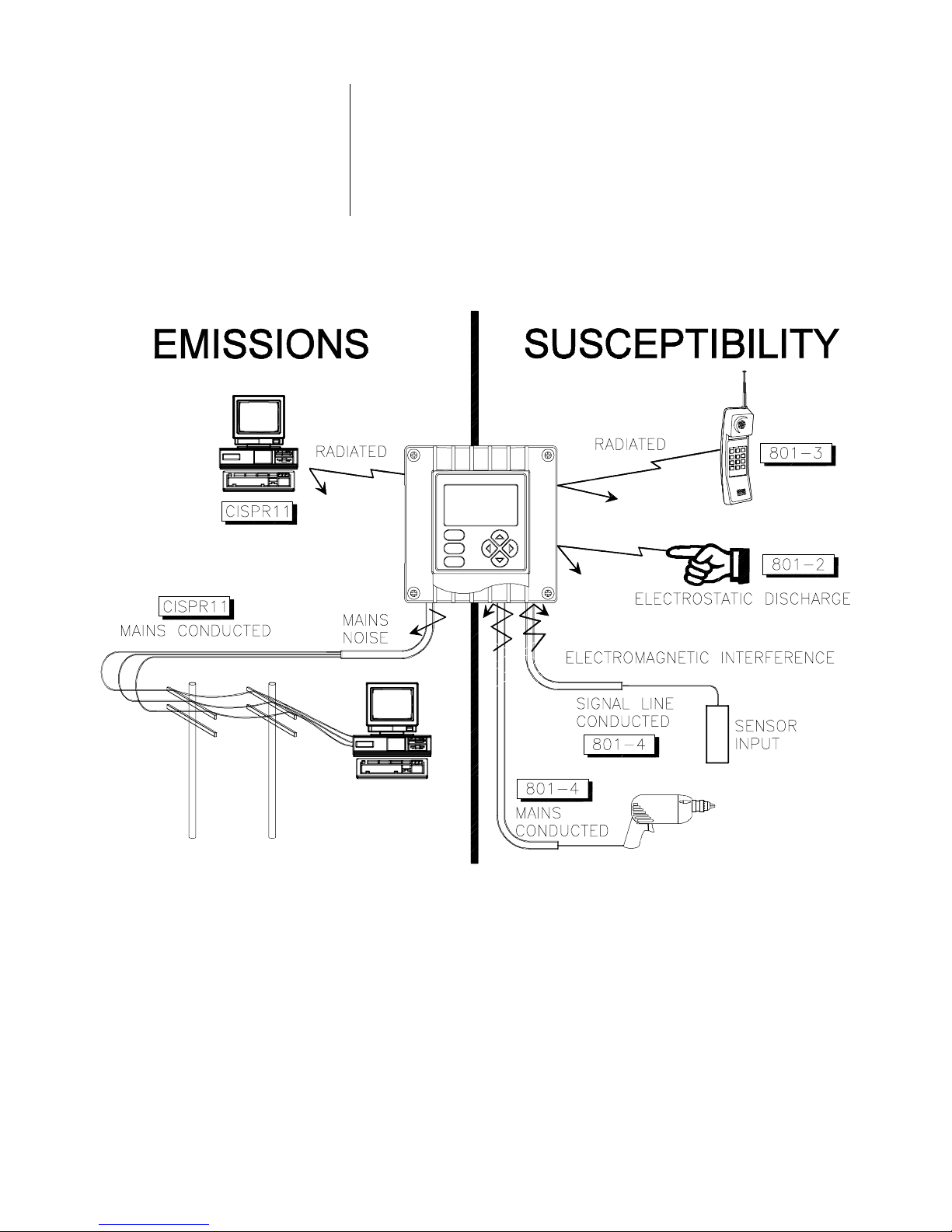
1.5 EMI/RFI Immunity
The analyzer is designed to provide protection from most
normally encountered electromagnetic interference. This
protection exceeds US standards and meets European
IEC 801-series testing for electromagnetic and radio frequency emissions and susceptibility. Refer to Figure 1-1
and the specifications in Section 2.1 for more information.
Model C53 Conductivity Analyzer (universal-mount 1/2 DIN) Rev. 5-1000
FIGURE 1-1 EMI/RFI Immunity Diagram
18

PART ONE - INTRODUCTION SECTION 2 - SPECIFICATIONS
ECTION
S
2
SPECIFICATIONS
2.1 Operational
Display....................................... Graphic dot matrix LCD, 128 x 64 pixels with
LED backlighting; 1/2 inch (13 mm) main
character height; 1/8 inch (3 mm) auxiliary
information character height; menu screens
contain up to six text lines
Measurement Selectable Ranges
Conductivity ..........................µS/cm: 0-2.000, 0-20.00, 0-200.0 or 0-2000
mS/cm: 0-2.000, 0-20.00, 0-200.0 or 0-2000
Resistivity ............................. 0-19.99 MΩ • cm or 0-19.99 KΩ • cm
TDS ...................................... 0-9999 ppm or 0-9999 ppb
Calculated Sensor A
and B Measurement:
% Rejection ....................... 0-100%
% Passage ........................ 0-100%
Ratio A/B or B/A ................ 0-9.999, 0-99.99, 0-999.9 or 0-9999
Difference A-B or B-A ........ Same ranges as those listed above for
conductivity, resistivity, or TDS
Temperature ......................... -4.0 to +392.0°F or -20.0 to +200.0°C
Analog Outputs (1 and 2) ...... 0.00-20.00 mA or 4.00-20.00 mA
Ambient Conditions:
Operation.............................. -4 to +140°F (-20 to +60°C); 0-95% relative
humidity, non-condensing
Storage................................. -22 to +158°F (-30 to +70°C); 0-95% relative
humidity, non-condensing
Relays: Types/Outputs .................Up to four electromechanical relays; SPDT
(Form C) contacts; U.L. rated 5A 115/230
VAC, 5A @ 30 VDC resistive
Operational Mode ............Each relay (A, B, C, and D) can be assigned to
be driven by the:
•
Selected Sensor A or B measurement (con-
ductivity, resistivity, TDS or temperature)
•
Calculated Sensor A and B measurement
(% rejection, % passage, ratio A/B, ratio
B/A, difference A-B or difference B-A)
Function Modes:
Control.................... Settings for high/low phasing, setpoint, dead-
band, overfeed timer, off delay, and on delay
Alarm..........................Settings for low alarm point, low alarm point
deadband, high alarm point, high alarm point
deadband, off delay, and on delay
Status.........................Not configurable; relay only activates when a
sensor or analyzer “fail” diagnostic WARNING
condition exists
Indicators.........................Relay A, B, C, and D annunciators indicate
respective relay on/off status
Temperature Compensation ....... Automatic or manual, -4.0 to 392.0°F (-20.0
to +200.0°C), with selection for Pt 1000
ohm RTD or Pt 100 ohm RTD temperature
element or an entered tem perature value for
fixed manual compensation
NOTE:
Depending on Sensor A or B’s selected measurement, only some
of the following temperature compensation methods are available:
Linear % per °C slope
•
Built-in ammonia temperature properties table
•
Built-in natural water temperature properties table
•
No compensation
•
Rev. 5-1000 Model C53 Conductivity Analyzer (universal-mount 1/2 DIN)
19

PART ONE - INTRODUCTION SECTION 2 - SPECIFICATIONS
Sensor-to-Analyzer Distance ...... 300 ft. (91 m) maximum
Power Requirements .................. 90-130 VAC, 50/60 Hz. (10 VA max.) or
180-260 VAC, 50/60 Hz. (10 VA max.)
Calibration Methods:
DRY-CAL................................ Enter GLI-certified cell constant “K” value and
temperature “T” factor of the sensor.
1 POINT SAMPLE .................. Enter one reference solution value or one
sample value (determined by laboratory
analysis or a comparison reading).
ZERO..................................... With the dry sensor in air, press keys to
initiate automatic system zeroing.
Analog Outputs .......................... Two isolated 0/4-20 mA outputs; each with
0.004 mA (12-bit) resolution and capability
to drive up to 600 ohm loads
NOTE:
Each output can be assigned to represent Sensor A or B’s selected
parameter (conductivity, resistivity or TDS), Sensor A or B’s tem-
perature or a calculated Sensor A and B measurement (% rejection,
% passage, ratio A/B, ratio B/A, difference A-B, or difference B-A).
Parameter (or calculated measurement) values can be entered to define the endpoints at which the minimum and maximum mA output
values are desired (range expand). During calibration, both outputs
can be selected to hold their present values, transfer to preset values
to operate control elements by an amount corresponding to those
values, or remain active to respond to the measured value.
Communication: RS-232 ........... Enables configuration and retrieval of measured
data for one analyzer using IBM-compatible
PC and optional GLI software tool kit
HART.............. Enables configuration and retrieval of measured
data for multiple analyzers over a communi-
cation link using an appropriate hand-held
terminal or data system with HART software
Memory Backup (non-volatile) .... All user settings are retained indefinitely in
memory (EEPROM)
EMI/RFI Conformance................ Exceeds US and meets European standards
for conducted and radiated emissions and
immunity; certified CE compliant for appli-
cations as specified by EN 50081-1 for
emissions and EN 50082-2 for immunity
Electrical Certifications:
General Purpose (pending) ..... UL, C-UL, FM, and CENELEC
Division 2 (pending) ................ UL, C-UL, and FM: Groups A, B, C, D, F, and G
Zone 2 (pending) .................... CENELEC: Group IIC
2.2 Analyzer Performance
(Electrical, Analog Outputs)
2.3 Mechanical
Model C53 Conductivity Analyzer (universal-mount 1/2 DIN) Rev. 5-1000
Accuracy .................................... 0.1% of span
Stability...................................... 0.05% of span per 24 hours, non-cumulative
Repeatability .............................. 0.1% of span or better
Temperature Drift....................... Zero and Span: less than 0.03% of span/°C
Enclosure................................... NEMA 4X; polycarbonate face panel, epoxy-
coated cast aluminum door and case with four
1/2 inch (13 mm) conduit holes; nylon mounting bracket, and stainless steel hardware
Mounting Configurations............. Panel, surface, and pipe (horizontal and
vertical) mounting
Net Weight................................. 3.5 lbs. (1.6 kg) approximately
20
PART TW O - INSTALLATION SECTION 1 - UNPACKING
PART TWO - INSTALLATION
ECTION
S
UNPACKING
After unpacking, it is recommended to save the shipping
carton and packing materials in case the instrument must be
stored or re-shipped. Inspect the equipment and packing
materials for signs of shipping damage. If there is any evidence of damage, notify the transit carrier immediately.
ECTION
S
MECHANICAL REQUIREMENTS
1
2
2.1 Location
1. It is recommended to locate the analyzer as close as
possible to the installed sensor. The maximum allowable distance between an installed sensor and the
analyzer is 300 feet (91 m).
2. Mount the analyzer in a location that is:
➥
Clean and dry where there is little or no vibration.
➥
Protected from corrosive fluids.
➥
Within ambient temperature limits (-4 to +140°F or
-20 to +60°C).
CAUTION:
EXPOSING THE ANALYZER TO DIRECT
SUNLIGHT MAY INCREASE THE OPERATING
TEMPERATURE ABOVE ITS SPECIFIED
LIMIT, AND DECREASE DISPLAY VISIBILITY.
RECOMMENDATION: IN SEVERE CASES,
USE A GLI SUN SHIELD (P/N 1000G3088-001).
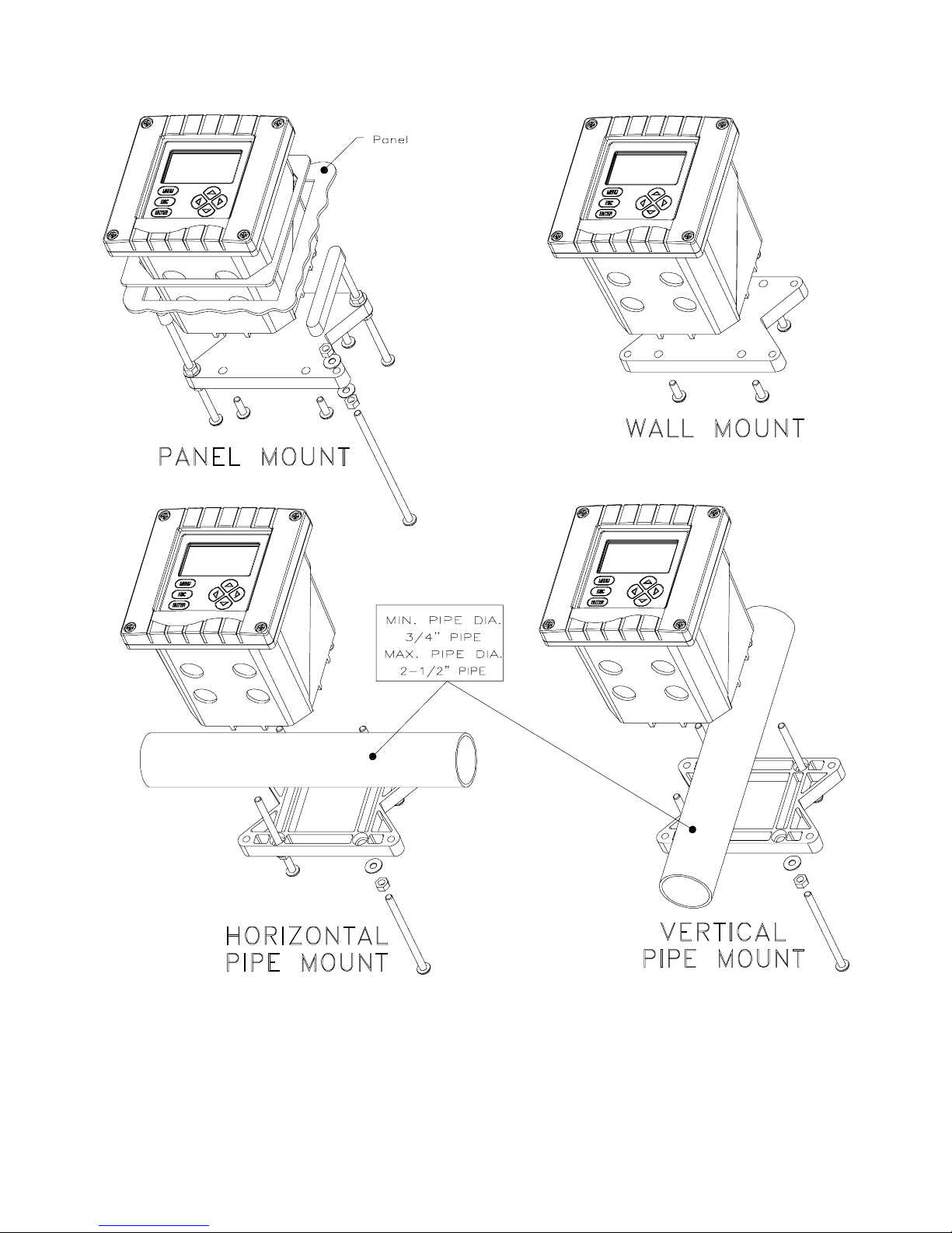
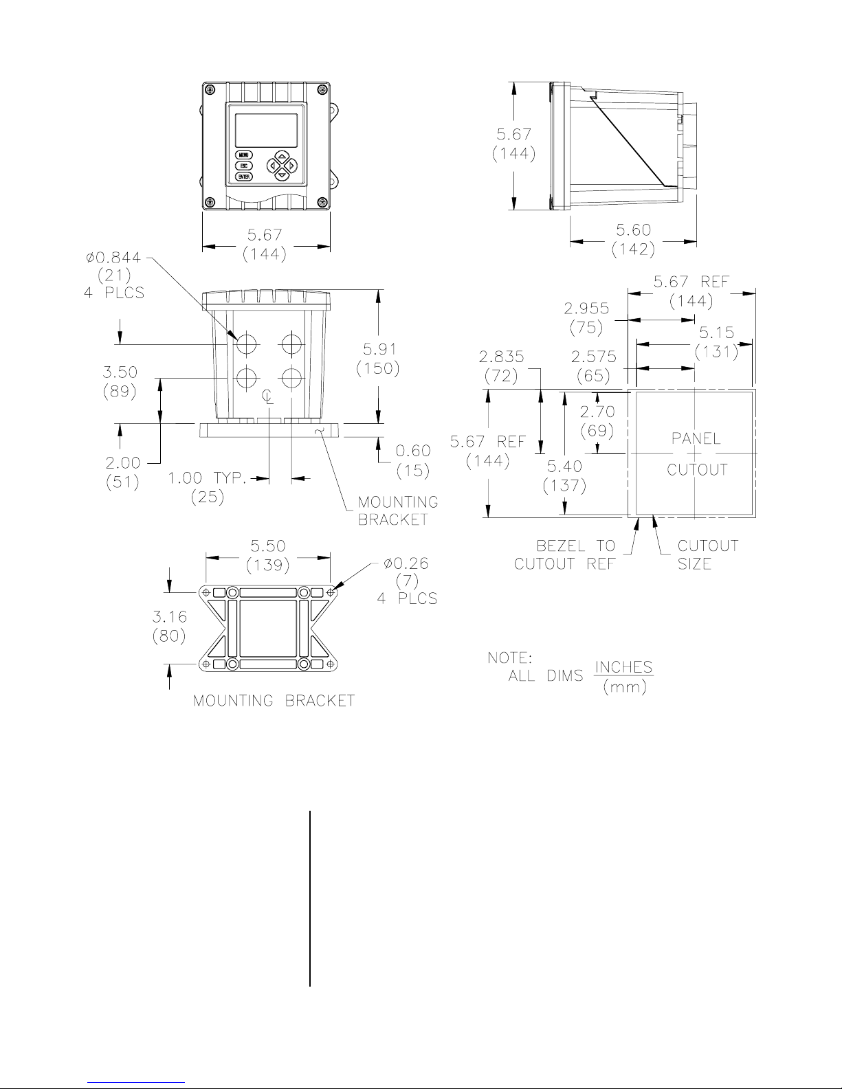
2.2 Mounting
Rev. 5-1000 Model C53 Conductivity Analyzer (universal-mount 1/2 DIN)
Figure 2-1 illustrates the various ways to mount the analyzer using the supplied bracket and hardware. Determine
the mounting method and attach the hardware as shown in
the respective illustration. Refer to Figure 2-2 for analyzer
installation dimension details.
21
PART TW O - INSTALLATION SECTION 2 - MECHANICAL REQUIREMENTS
FIGURE 2-1 Analyzer Mounting Arrangements
Model C53 Conductivity Analyzer (universal-mount 1/2 DIN) Rev. 5-1000
22
PART TW O - INSTALLATION SECTION 2 - MECHANICAL REQUIREMENTS
FIGURE 2-2 Analyzer Installation Dimensions Details
2.3 Conduit Hole
Requirements
☞
Rev. 5-1000 Model C53 Conductivity Analyzer (universal-mount 1/2 DIN)
Recommendation:
inch, grounded metal conduits. If using only shielded cables, appropriate strain reliefs or cable grips are required.
(GLI offers accessory cable grips, part number 3H1091, and
watertight locknuts, part number 3H1230, for cable entries.)
Seal unused cable entry holes with appropriate plugs.
NOTE:
Use NEMA 4-rated fittings and plugs to maintain the
Run all wiring to the analyzer in 1/2-
watertight integrity of the NEMA 4X enclosure.
23
PART TW O - INSTALLATION SECTION 3 - ELECTRICAL CONNECTIONS
ECTION
S
ELECTRICAL CONNECTIONS
To access terminals for electrical connections, open the lefthinged enclosure door by unscrewing the four fasteners.
Figure 2-3 or 2-4 shows the terminal arrangement and their
designations.
3
☞
☞
NOTE: All terminals are suitable for single wires up to 14
AWG (2.5 mm2). If the analyzer is equipped with
only relays A and B, “RELAY C” and “RELAY D”
terminals will not function (all relay designations are
always shown).
Wiring Tip!
electromagnetic compatibility requirements, follow these
general wiring guidelines:
1. Keep all cable shields as short as possible inside
the analyzer, and connect them to the ground terminals provided. Performance may be improved by
using cable glands that enable the shield to directly
contact the analyzer chassis.
2. Use Steward ferrite 28 B0590-000 or equivalent on
the sensor cable -- two turns required.
3. In harsh conducted RF conditions, connect the earth
ground of the analyzer to a local, known earth
ground source.
To comply with European Community (CE)
☞
3.1 GLI Enhanced Performance Contacting
Conductivity Sensor(s)
Model C53 Conductivity Analyzer (universal-mount 1/2 DIN) Rev. 5-1000
NOTE: For easier wiring, connect line power and relay out-
puts through the back conduit holes before connecting
sensor and analog outputs through the front holes.
All GLI Model 3400-series contacting conductivity sensors
have a built-in Pt 1000 ohm RTD temperature element for
automatic temperature compensation.
Wiring Tip!
grounded metal conduit to protect it from moisture,
electrical noise, and mechanical damage.
For installations where the distance between sensor and
analyzer exceeds the sensor cable length, indirectly
connect the sensor to the analyzer using a junction box
and interconnect cable.
Route the sensor cable in 1/2-inch,
24

PART TW O - INSTALLATION SECTION 3 - ELECTRICAL CONNECTIONS
☞
NOTE: Do not route the sensor cable in any conduit con-
taining AC or DC power wiring (“electrical noise”
may interfere with the sensor signal). Also, always
re-calibrate the system when the cable length between sensor and analyzer changes.
RS-232
4-20 mA
OUTPUT 1+OUTPUT 2
+
HART
TX
-
-
4325871092122 1920 13151618 14 12
TWO ELECTRODE CON DUCTIVITY ANALYZER
RELAY A
NC COM
TB2
GNDRX GND
6
RELAY B
NO
COMNC NCNO
3312 5476
90-130 VAC
180-260 VAC
10VA 50/60 Hz
TTL
+
POWER
SENSOR A
INNER
RED
RELAY C
COM
8
BLUE
WHITE
BLACK
SHIELD
RELAY D
NCNO NOCOM
1091211 342
F1F
80mA
T
SENSOR B
INNER
RED
BLACK
2
100mA
T
WHITE
SHIELD
115230 N
BLUE
TB1
TB3
FIGURE 2-3 Terminal Designations for Analyzers with “B” Prefix Serial Number
FIGURE 2-4 Terminal Designations for Analyzers with “A” or No Letter Prefix Serial Number
Rev. 5-1000 Model C53 Conductivity Analyzer (universal-mount 1/2 DIN)
25
PART TW O - INSTALLATION SECTION 3 - ELECTRICAL CONNECTIONS
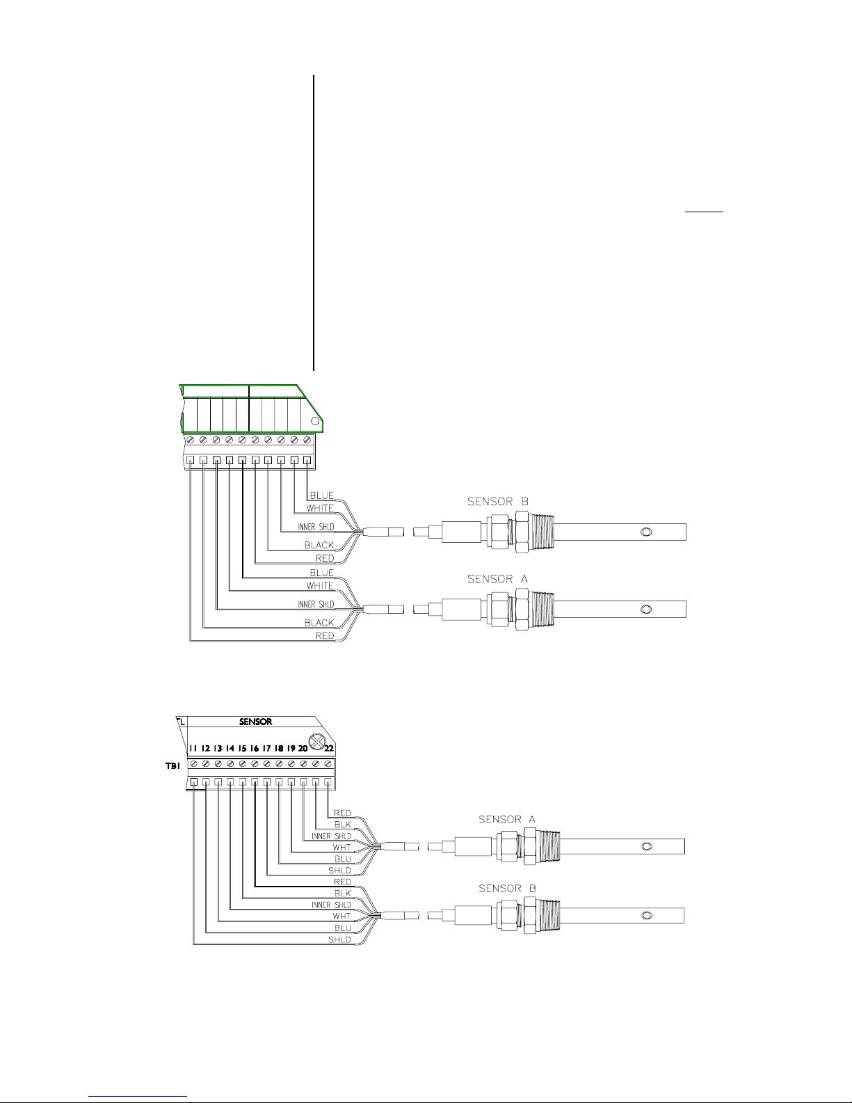
The analyzer can be used with one or two conductivity sensors. Refer to Figure 2-5 or 2-6 and connect the wires of
each sensor (or interconnect) cable to appropriate terminals
on TB1, matching colors as indicated.
SENSOR A
INNER
RED
BLACK
SHIELD
2122 1920 13151618 14 12
TB1
WHITE
SENSOR B
BLUE
RED
☞
INNER
BLACK
SHIELD
NOTE: For best immunity to electromagnetic interference,
always connect each sensor cable’s outer shield
wire (clear with black band -- not its clear-only inner
shield wire) to:
•
Grounding strip at bottom of case (5 open holes)
for analyzers with “B” prefix serial number.
•
Terminal 17 and Terminal 11 on TB1 for each
respective sensor for analyzers with “A” or no
letter prefix serial number.
WHITE
BLUE
FIGURE 2-5 Connecting GLI Contacting Conductivity Sensor(s) to Analyzers with “B” Prefix Serial Number
FIGURE 2-6 Connecting GLI Contacting Conductivity Sensor(s)
to Analyzers with “A” or No Letter Prefix Serial Number
Model C53 Conductivity Analyzer (universal-mount 1/2 DIN) Rev. 5-1000
26
PART TW O - INSTALLATION SECTION 3 - ELECTRICAL CONNECTIONS
3.2 Analog Outputs
☞
Two isolated analog outputs (1 and 2) are provided. Each
output can be set to be 0-20 mA or 4-20 mA, and assigned
to represent one of the following:
•
Measured Sensor A conductivity, resistivity or TDS.
•
Measured Sensor A temperature.
•
Measured Sensor B conductivity, resistivity or TDS.
•
Measured Sensor B temperature.
•
*Calculated Sensor A and B measurement (% reject, %
pass, ratio A/B, ratio B/A, diff. A-B, or diff. B-A).
*An analog output can only represent the calculated measurement when two sen-
sors are used and the analyzer has been correctly configured for CALCULATION.
The outputs are isolated from the inputs and earth
ground, but not from each other.
details, see PART THREE, Section 4.5.
Wiring Tip!
cable for connecting the analog outputs. To protect the
output signal from EMI/RFI, connect cable shields to:
Use high quality, shielded instrumentation
For output configuration
☞
The grounding strip at bottom of case (5 open holes,
Fig. 2-3) for analyzers with “B” prefix serial number.
The “ground symbol” Terminal 1 on TB1 (Figure 2-4)
for analyzers with “A” or no letter prefix serial number.
Each 0/4-20 mA output can drive a load of up to 600 ohms.
• Output 1: Connect the load to Terminals 2 and 3 on TB1,
matching polarity as indicated.
• Output 2: Connect the load to Terminals 4 and 5 on TB1,
matching polarity as indicated.
NOTE: When using the HART communication option, a
digital signal is encoded onto the 4-20 mA analog
Output 1 signal. In a HART point-to-point wiring
configuration, Output 1 remains available for normal
use. However, in a HART multi-drop wiring configuration, Output 1 becomes dedicated to that function
and cannot be used. See PART THREE, Section 8
for more HART communication information.
Rev. 5-1000 Model C53 Conductivity Analyzer (universal-mount 1/2 DIN)
27
PART TW O - INSTALLATION SECTION 3 - ELECTRICAL CONNECTIONS
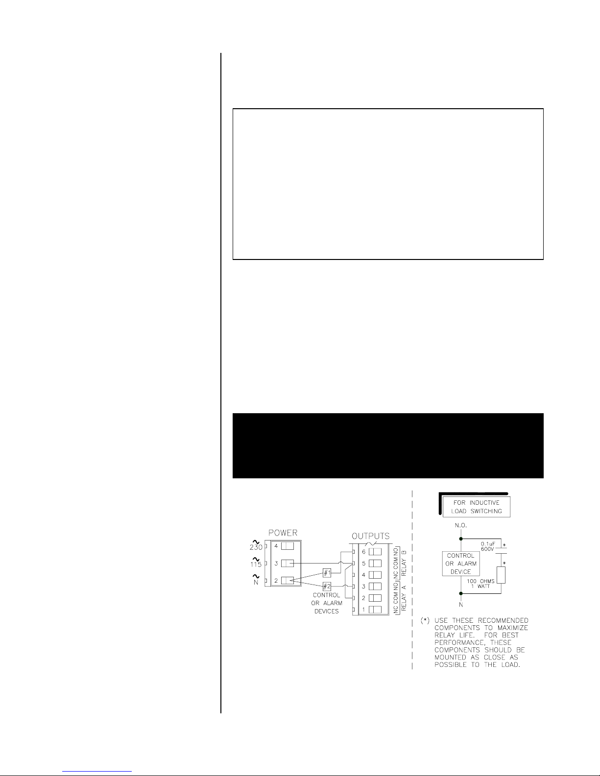
3.3 Relay Outputs
The analyzer may be equipped with up to four electromechanical relays. For relay setup details, see PART THREE,
Section 4.6.
CAUTION:
DO NOT EXCEED THE CONTACT RATING FOR
EACH RELAY (5A 115/230 VAC). WHEN SWITCHING
LARGER CURRENTS, USE AN AUXILIARY RELAY
SWITCHED BY THE ANALYZER RELAY TO EXTEND
ANALYZER RELAY LIFE. WHEN USING RELAY
OUTPUTS, MAKE SURE THAT LINE POWER WIRING
CAN ADEQUATELY CONDUCT THE CURRENT
DRAW OF THE SWITCHED LOAD(S).
Up to four sets of SPDT relay outputs (Relays A, B, C, and
D) are provided at Terminals 1 through 12 on TB2.
lay outputs are not powered.
The line power used to
The re-
power the analyzer may also be used to power control/alarm devices with these relay contacts. Refer to Figure
2-7 for a general wiring arrangement. Always check control
wiring to insure that line power will not be shorted by the
relay switching action, and that wiring conforms to local
codes.
WARNING:
MAKE SURE LINE POWER IS NOT PRESENT WHILE
CONNECTING WIRES TO TB2 RELAY TERMINALS.
FIGURE 2-7
Connecting Control/Alarm Device(s) To Electromechanical Relay(s)
Model C53 Conductivity Analyzer (universal-mount 1/2 DIN) Rev. 5-1000
28
PART TW O - INSTALLATION SECTION 3 - ELECTRICAL CONNECTIONS
3.4 Closed Contact
TTL Input
3.5 Line Power
☞
The closed contact input feature of the analyzer enables
you to conveniently:
•
Hold analog outputs at their present values.
•
Hold CONTROL and ALARM relays in their present
on/off transfer states.
To initiate these actions, momentarily connect TTL Terminals 9 and 10 on TB1, either locally or remotely:
NOTE: During calibration, the selected output state (“HOLD,”
“XFER” or “ACTIVE”) overrides the TTL input hold
feature.
Refer to appropriate figures on the next page and connect
line power to TB3 terminals using the standard three-wire
connection arrangement.
form to local codes
Handbook in the U.S.A.).
Use wiring practices which con-
(example: National Electric Code
☞
WARNING:
REMOVE LINE POWER WHILE CONNECTING LINE
POWER WIRES TO THE TB3 TERMINALS. ALSO,
USE ONLY THE STANDARD THREE-WIRE CONNECTION ARRANGEMENT FOR SINGLE-PHASE LINE
POWER TO PREVENT AN UNSAFE CONDITION, AND
TO ENSURE PROPER ANALYZER OPERATION.
NOTE: In all cases, connect the line power cable ground
wire (usually green) to:
The grounding strip at bottom of case (5 open
holes -- Figures 2-8, 2-10 or 2-12) for analyzers
with “B” prefix serial number.
The “ground symbol” terminal 1 on TB3 (Figures
2-9, 2-11 or 2-13) for analyzers with “A” or no
letter prefix serial number.
The “115” and “230” voltage circuits are protected with internal, board-mounted slow-blow fuses.
☞
Rev. 5-1000 Model C53 Conductivity Analyzer (universal-mount 1/2 DIN)
NOTE: For 230 volt split phase line power, be sure to con-
form to local codes with regard to fusing the 115
volt line connected to the “N” terminal.
29
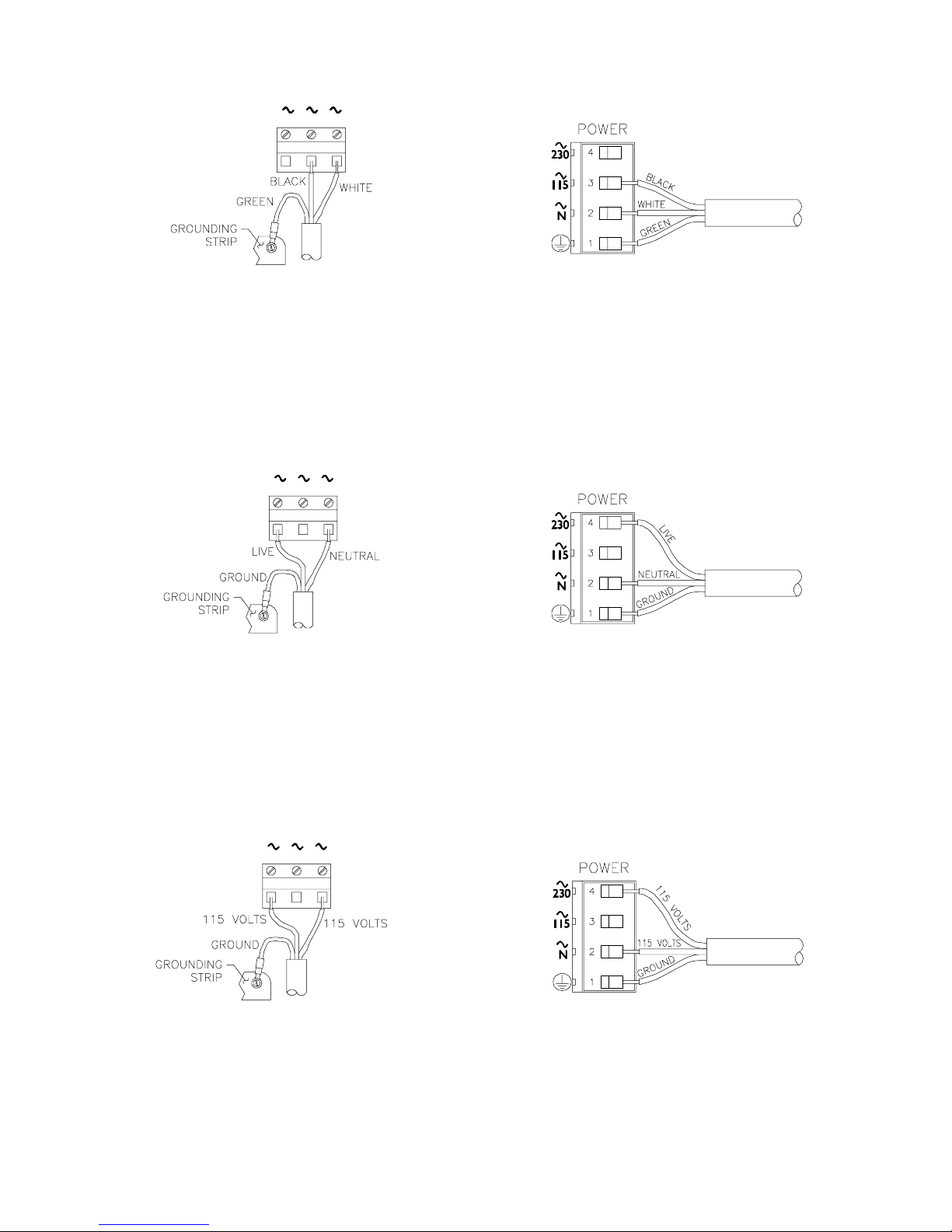
PART TW O - INSTALLATION SECTION 3 - ELECTRICAL CONNECTIONS
115230 N
342
FIGURE 2-8
Connecting 115 Volt Single Phase
to Analyzers with “B” Prefix Serial Number
230 115 N
234
FIGURE 2-10
Connecting 230 Volt Single Phase
to Analyzers with “B” Prefix Serial Number
FIGURE 2-9
Connecting 115 Volt Single Phase
to Analyzers with “A” or No Letter Prefix Serial Number
FIGURE 2-11
Connecting 230 Volt Single Phase
to Analyzers with “A” or No Letter Prefix Serial Number
N115230
234
FIGURE 2-12
Connecting 230 Volt Split Phase
to Analyzers with “B” Prefix Serial Number
Model C53 Conductivity Analyzer (universal-mount 1/2 DIN) Rev. 5-1000
FIGURE 2-13
Connecting 230 Volt Split Phase
to Analyzers with “A” or No Letter Prefix Serial Number
30
 Loading...