


OPERATING INSTRUCTION MANUAL
Accu4™
Low-range
Turbidimeter System
(Model T53 Analyzer and 8320 Sensor)
Worldwide Headquarters and Sales:
GLI International, Inc.
9020 West Dean Road
Milwaukee, Wisconsin 53224
U.S.A.
In the interest of improving and updating its equipment, GLI reserves the right to alter specifications to equipment at any time.
Rev. 2-300 Accu4™ Low-range T urbidimeter Sys tem
Phone:
Fax:
E-mail:
Web:
Represented By:
[414] 355-3601
[414] 355-8346
info@gliint.com
www.gliint.com
Viridor Instrumentation
A company
1

Accu4™ Low-range Turbidimeter System Rev. 2-300
2

IMPORTANT SAFETY INFORMATION
This measurement system is compliant with safety standards as outlined in:
FMRC Class Numbers 3600, 3611, and 3810 (U.S.A.)
CSA C22.2 No. 142 and C22.2 No. 213 (Canada)
EN 61010-1 (European Community)
Please read and observe the following:
•
Opening the analyzer door exposes you to line power voltage, if present, at terminals on TB2 and TB3
inside the enclosure. This may be hazardous. Always remove line power before entering this area in
the analyzer. However, the analyzer door assembly and the sensor contain only low voltages and are
completely safe to handle.
•
Wiring or repairs should only be performed by qualified personnel and only to an unpowered analyzer.
•
Whenever it appears that analyzer safety is questionable, disable the analyzer to ensure against any
unintended operation. For example, an unsafe condition is likely when:
1) The analyzer appears visibly damaged.
2) The analyzer fails to operate properly or provide the intended measurements.
3) The analyzer has been stored for long periods at temperatures above 158°F (70°C).
•
This measurement system must be installed by specially trained personnel in accordance with relevant
local codes and instructions contained in this operating instruction manual. Observe all technical
specifications of the system. If one line of the line power mains is not neutral, use a double-pole mains
switch to disconnect the analyzer.
HELPFUL IDENTIFIERS
In addition to information on installation and operation, this instruction manual may contain
WARNINGS pertaining to user safety, CAUTIONS regarding possible instrument malfunction, and
NOTES on important, useful operating guidelines.
WARNING:
A WARNING LOOKS LIKE THIS. IT WARNS YOU OF THE POTENTIAL
FOR PERSONAL INJURY.
CAUTION:
A CAUTION LOOKS LIKE THIS. IT ALERTS YOU TO POSSIBLE
INSTRUMENT MALFUNCTION OR DAMAGE.
☞
NOTE: A note looks like this. It alerts you to important operating
information.
Rev. 2-300 Accu4™ Low-range Turbidimeter System
3
Definition of Equipment Symbols
This symbol
means CAUTION
and alerts you to possible danger or
instrument malfunction. Refer to this manual before proceeding.
This symbol
means that this is a protective ground terminal
alerts you to connect an earth ground to it.
This symbol
means that there is alternating current present
alerts you to be careful.
and
and
WARRANTY
GLI International, Inc. warrants the Accu4™ Low-range Turbidimeter System to be free
from defects in material or workmanship for a period of 2 years (24 months) from the
date this product was shipped from our facility. A warranty claim will not be honored if
defects are not reported within the warranty period, or if GLI International determines that
defects or damages are due to normal wear, misapplication, lack of maintenance, abuse,
improper installation, alteration, or abnormal conditions. GLI International’s obligation
under this warranty shall be limited to, at its option, replacement or repair of this product.
The product must be returned to GLI International, freight prepaid, for examination. The
product must be thoroughly cleaned and any process chemicals removed before it will be
accepted for replacement or repair. GLI International’s liability shall not exceed the cost
of the product. Under no circumstances will GLI International be liable for any incidental
or consequential damages, whether to person or property. GLI International will not be liable for any other loss, damage or expense of any kind, including loss of profits,
resulting from the installation, use, or inability to use this product.
Accu4™ Low-range Turbidimeter System Rev. 2-300
4
CONDENSED OPERATING INSTRUCTIONS
This manual contains details for all operating aspects of the Accu4™ Low-range Turbidimeter System.
The following condensed instructions are provided to assist you in getting the system started up and operating as quickly as possible.
measurement operation.
To use specific analyzer features, refer to the appropriate sections in this
manual for instructions.
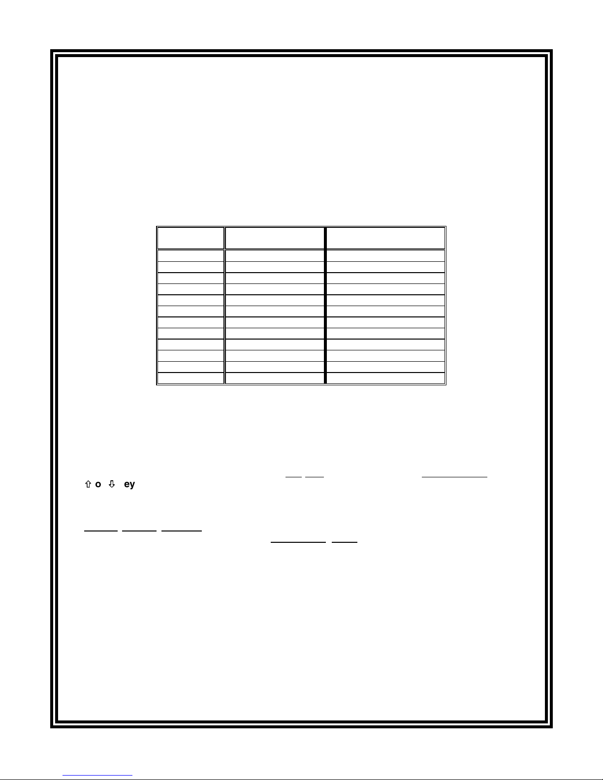
1. CONNECTING SENSOR
After the T53 analyzer is properly mounted (Part Two, Section 2.5), connect the GLI Model 8320 lowrange turbidity sensor, matching wire colors to terminals as indicated:
These condensed instructions only pertain to basic turbidity
Sensor Wire
Colors
Inner Shield Grounding strip lug Terminal #11 on TB1
Red Terminal #12 on TB1 Terminal #12 on TB1
Violet Terminal #13 on TB1 Terminal #13 on TB1
Green Terminal #14 on TB1 Terminal #14 on TB1
White Terminal #15 on TB1 Terminal #15 on TB1
Yellow Terminal #16 on TB1 Terminal #16 on TB1
Inner Shield Grounding strip lug Terminal #17 on TB1
Brown Terminal #18 on TB1 Terminal #18 on TB1
Gray Terminal #19 on TB1 Terminal #19 on TB1
Blue Terminal #20 on TB1 Terminal #20 on TB1
Black Terminal #21 on TB1 Terminal #21 on TB1
Orange Terminal #22 on TB1 Terminal #22 on TB1
Analyzers with
“B” Prefix Serial No.
Analyzers with
No Letter Prefix Serial No.
2. CONNECTING LINE POWER
Important:
Follow the instructions in Part Two, Section 3.5 to connect line power to the analyzer.
3. ADJUSTING DISPLAY CONTRAST
Ambient lighting conditions may make it necessary to adjust display contrast to improve visibility.
With the MEASURE screen displayed, press and hold
×
Ø
×
or
until attaining the desired contrast.
key
Ø
ENTER key
the
and simultaneously press the
4. CALIBRATING SYSTEM
Always initially
calibrate
the Accu4™ Low-range Turbidimeter System to ensure accurate measurement. Any time thereafter, you can conveniently check system calibration using an optional
accessory Cal-CubeTM assembly.
•
When you need to calibrate with a
method. GLI only guarantees measurement accuracy when a 40 NTU formazin suspension is used
as the primary standard.
•
When calibration need not conform to USEPA requirements
method (requires optional GLI CAL-CUBE™ assembly) or the “SAMPLE CAL” method.
Refer to Part Three, Section 5 for instructions on all calibration methods.
5. COMPLETING ANALYZER CONFIGURATION
To further configure the analyzer to your application requirements, use the appropriate CONFIGURE
screens to make selections and “key in” values. Refer to Part Three, Section 4 for complete configuration details.
Rev. 2-300 Accu4™ Low-range Turbidimeter System
primary standard
5
, use the “PRIMARY CAL” calibration
, use the “CUBE CAL” calibration

Accu4™ Low-range Turbidimeter System Rev. 2-300
6

TABLE OF CONTENTS
PART ONE - INTRODUCTION
SECTION 1 GENERAL INFORMATION
1.1 Capability Highlights ........................................................................13-15
1.2 Modular Construction ............................................................................15
1.3 Retained Configuration Values .............................................................15
1.4 Analyzer and Sensor Serial Numbers ...................................................15
1.5 EMI/RFI Immunity.................................................................................. 16
SECTION 2 SPECIFICATIONS
....................................................................................17-18
PART TWO - INSTALLATION
SECTION 1 UNPACKING
SECTION 2 MECHANICAL REQUIREMENTS
2.1 Sensor Location ...............................................................................19-20
2.2 Sensor Mounting ..............................................................................20-21
2.3 Sensor Plumbing Connections ..............................................................22
2.4 Analyzer Location..................................................................................23
2.5 Analyzer Mounting............................................................................23-24
2.6 Sensor and Analyzer Conduit Hole Requirements................................ 24
SECTION 3 ELECTRICAL CONNECTIONS
3.1 GLI Model 8320 Low-range Turbidity Sensor...................................25-27
3.2 Analog Outputs......................................................................................28
3.3 Relay Outputs...................................................................................28-29
3.4 Closed Contact TTL Input .....................................................................29
3.5 Line Power .......................................................................................30-31
.................................................................................................19
PART THREE - OPERATION
SECTION 1 USER INTERFACE
1.1 Display ..................................................................................................32
1.2 Keypad .............................................................................................32-33
1.3 MEASURE Screen (normal display mode)............................................ 34
SECTION 2 MENU STRUCTURE
2.1 Displaying Main Branch Selection Screen ............................................35
2.2 Displaying Top-level Menu Screens.................................................35-36
2.3 Displaying Submenu Screens ...............................................................36
2.4 Adjusting Edit/Selection Screen Values ...........................................36-37
2.5 Entering (Storing) Edit/Selection Screen Values/Choices.....................37
Rev. 2-300 Accu4™ Low-range Turbidimeter System
7

TABLE OF CONTENTS (continued)
SECTION 3 ADJUSTING DISPLAY CONTRAST
SECTION 4 CONFIGURING THE ANALYZER
4.1 Selecting LANGUAGE to Operate Analyzer.......................................... 38
4.2 Configuring Sensor Characteristics:
SELECT UNITS ..........................................................................38-39
SET FILTER Time............................................................................ 39
Select PULSE SUPPRESS (on/off)..................................................40
ENTER NOTE (top line of MEASURE screen).................................40
4.3 Configuring Analog Outputs (1 and 2):
SET 0/4 and 20 mA VALUES......................................................41-42
SET TRANSFER Value (mA)........................................................... 42
SET FILTER Time............................................................................ 43
Select SCALE 0 mA/4 mA (low endpoint) ........................................43
4.4 Configuring Relays (A, B, C, and D):
SET FUNCTION Mode (alarm, control, or status).......................44-45
SET TRANSFER Mode (relay on or off) ..........................................46
SET ACTIVATION (configuration values) ...................................46-48
4.5 SET PASSCODE (feature enabled or disabled) ...................................48
4.6 Configuration Settings Summary (ranges/choices and defaults) ..........49
.............................................................37
SECTION 5 CALIBRATING THE ANALYZER
5.1 Things to Know About Calibration ....................................................50-51
5.2 PRIMARY CAL Method (requires formazin suspension):
Preparing Formazin Solution ......................................................51-52
Filling Sensor..............................................................................52-54
Entering Value .................................................................................54
Resuming Operation ...................................................................54-55
5.3 CUBE CAL Method (requires optional Cal-CubeTM assembly):
TM
Inserting Cal-Cube
Assembly ..................................................55-56
Entering Value ............................................................................56-57
Resuming Operation ........................................................................57
5.4 SAMPLE CAL Method (requires sample with value
determined by laboratory analysis or portable meter)......................57-59
5.5 Analog Outputs (1 and 2) Calibration...............................................59-60
SECTION 6 TEST/MAINTENANCE
6.1 STATUS Checking (analyzer, sensor, and relays)...........................61-63
6.2 CHECK CAL/HOLD Outputs ............................................................63-64
6.3 OVERFEED RESET (relay timers)........................................................ 65
6.4 OUTPUT (1 and 2) Analog Test Signals ..........................................65-66
6.5 RELAY (A, B, C, and D) Operating Test................................................66
6.6 SENSOR TYPE Checking................................................................66-67
6.7 EPROM VERSION Checking ................................................................67
Accu4™ Low-range Turbidimeter System Rev. 2-300
8

TABLE OF CONTENTS (continued)
6.8 SIM SENSOR Setting.......................................................................67-68
6.9 RESET DEFAULTS............................................................................... 68
SECTION 7 RELAY OVERFEED TIMER FEATURE
7.1 Why Use an Overfeed Timer................................................................. 69
7.2 Configuring Relay Overfeed Timers......................................................69
7.3 Overfeed Timer “Timeout” Operation .................................................... 69
7.4 Resetting Overfeed Timers ...................................................................69
7.5 Interactions with Other Analyzer Functions......................................69-70
SECTION 8 HART OPTION
8.1 Introduction ...........................................................................................71
8.2 Analyzer Operating Modes for HART Network.................................72-73
8.3 SINGLE MODE (Point-to-Point) Wiring Arrangement ...........................73
8.4 MULTI-DROP Wiring Arrangement.......................................................74
8.5 HART Preferences Setup:
Changing Polling Address ...............................................................75
Viewing Number of Required Preambles ....................................75-76
8.6 Device Preferences Setup:
Viewing Final Assembly Number ..................................................... 76
Viewing Model Number...............................................................76-77
Viewing Manufacturer ......................................................................77
Assigning a Tag ...............................................................................77
Assigning a Descriptor ..................................................................... 78
Assigning a Message....................................................................... 78
Assigning User-defined Date ......................................................78-79
Viewing Identification (ID) ................................................................79
Viewing Revisions............................................................................ 79
8.7 “Master Reset” Function........................................................................ 80
8.8 “Refresh” Function ................................................................................80
8.9 Protocol Command Set for PC Programming........................................ 80
PART FOUR - SERVICE AND MAINTENANCE
SECTION 1 GENERAL INFORMATION
1.1 Cleaning Sensor Flow Chamber ......................................................81-82
1.2 Cleaning Optional Cal-CubeTM Assembly.............................................. 82
1.3 Replacing Sensor Light Source or Detector:
Removing Inoperative Part ..............................................................83
Installing New Part ......................................................................83-84
Re-calibrating Measurement System............................................... 84
1.4 Replacing Fuse(s) .................................................................................85
1.5 Replacing Relays ..................................................................................85
1.6 Inspecting Sensor Cable .......................................................................85
Rev. 2-300 Accu4™ Low-range Turbidimeter System
9

TABLE OF CONTENTS (continued)
SECTION 2 PRESERVING MEASUREMENT ACCURACY
2.1 Eliminating Bubbles in Sensor Flow Chamber:
Restricting Sensor Outlet .................................................................86
Using an External Bubble Trap ........................................................86
2.2 Keeping Sensor Flow Chamber Clean ..................................................87
2.3 Keeping System Calibrated...................................................................87
2.4 Avoiding Electrical Interference.............................................................87
SECTION 3 TROUBLESHOOTING
3.1 System Diagnostic Condition Messages ............................................... 88
3.2 Isolating the Problem:
Checking Electrical Connections ..................................................... 89
Checking Operation Using System Diagnostics ..............................89
SECTION 4 ANALYZER REPAIR/RETURN
4.1 Customer Assistance.............................................................................90
4.2 Repair/Return Policy .............................................................................90
PART FIVE - SPARE PARTS AND ACCESSORIES
.................................................................................................................91
Accu4™ Low-range Turbidimeter System Rev. 2-300
10

TABLE OF CONTENTS (continued)
ILLUSTRATIONS
Figure 1-1
Figure 2-1
Figure 2-2
Figure 2-3
Figure 2-4
Figure 2-5
Figure 2-6
Figure 2-7
Figure 2-8
Figure 2-9
Figure 2-10
Figure 2-11
Figure 2-12
Figure 2-13
Figure 2-14
Figure 2-15
Figure 2-16
Figure 2-17
Figure 2-18
Figure 3-1
Figure 3-2
Figure 3-3
Figure 3-4
Figure 4-1
Figure 4-2
Figure 4-3
EMI/RFI Immunity Diagram ..................................................................................................16
Recommended Closed-loop Sensor Piping Arrangement...................................................... 19
Recommended Sample Bypass Line Sensor Piping Arrangement ........................................ 20
Standard Design Model 8320 Sensor -- Installation Dimension Details..................................21
High Pressure Design Model 8320 Sensor -- Installation Dimension Details.......................... 21
Sampling Point Guidelines for Process Pipe Plumbing Connection.......................................22
Analyzer Mounting Arrangements ......................................................................................... 23
Analyzer Installation Dimension Details ................................................................................ 24
Terminal Block Designations for Analyzers with “B” Prefix Serial Number.............................26
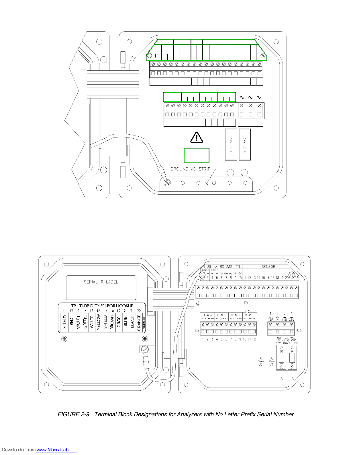
Terminal Block Designations for Analyzers with No Letter Prefix Serial Number ................... 26
Connecting Model 8320 Low-range Turbidity Sensor to
Analyzers with “B” Prefix Serial Number...............................................................................27
Connecting Model 8320 Low-range Turbidity Sensor to
Analyzers with No Letter Prefix Serial Number .....................................................................27
Connecting Control/Alarm Device(s) to Electromechanical Relay(s) .....................................29
Connecting 115 V Single Phase to Analyzers with “B” Prefix Serial Number.........................30
Connecting 115 V Single Phase to Analyzers with No Letter Prefix Serial Number ...............30
Connecting 230 V Single Phase to Analyzers with “B” Prefix Serial Number.........................31
Connecting 230 V Single Phase to Analyzers with No Letter Prefix Serial Number ...............31
Connecting 230 V Split Phase to Analyzers with “B” Prefix Serial Number............................ 31
Connecting 230 V Split Phase to Analyzers with No Letter Prefix Serial Number .................. 31
Analyzer Keypad ..................................................................................................................33
Location of SINGLE MODE/MULTI-DROP Switch (HART-equipped analyzers only).............73
HART SINGLE MODE (Point-to-Point) Wiring Arrangement (for single analyzer) .................73
HART MULTI-DROP Wiring Arrangement (for multiple analyzer network) ............................ 74
Standard Design Sensor -- Component Details ..................................................................... 81
High Pressure Design Sensor -- Component Details .............................................................82
Turbidity Sensor Terminal Block Designations...................................................................... 84
Table A
Table B
Table C
Table D
Rev. 2-300 Accu4™ Low-range Turbidimeter System
Relay Configuration Settings ...........................................................................................46-47
Analyzer Configuration Settings (Ranges/Choices and Defaults) ..........................................49
Relay Overfeed Timer Interactions with Other Analyzer Functions........................................70
System Diagnostic Condition Status Screens/Meanings........................................................88
TABLES
11

Accu4™ Low-range Turbidimeter System Rev. 2-300
12

PART ONE - INTRODUCTION SECTION 1 - GENERAL INFORMATION
PART ONE - INTRODUCTION
ECTION
1.1 Capability Highlights
High Accuracy with
Minimal Maintenance
S
GENERAL INFORMATION
The Accu4™ Low-range Turbidimeter System employs a
technologically-advanced sensor to provide high measurement accuracy and stability, while reducing maintenance
requirements. It is designed to meet the International Standards For Measurement of Turbidity [ISO 7027-1984(E)]
and USEPA-approved GLI Method 2. This system has an
auto-ranging measuring scale, enabling continuous monitoring over a 0.000-100.0 NTU range with automatic
decimal point positioning.
dimeter System automatically provides increasing
display resolution as measured turbidity decreases.
further ensure high measuring accuracy, the Model 8320
sensor eliminates air or gas bubbles in the sample with its
built-in bubble trap. The system is ideal for critical monitoring and controlling applications including potable water,
filtered water, and final product clarity.
1
The Accu4™ Low-range Turbi-
To
MEASURE Screen
Passcode-protected
Access
Calibration Methods
With the display in the normal MEASURE screen mode, the
measured turbidity is always shown on the main middle line.
The bottom auxiliary display line, shown in reverse video,
can be changed by pressing the
these measurements:
• Analog Output 1 value (mA)
• Analog Output 2 value (mA)
For security, you can enable a passcode feature to restrict
access to configuration and calibration settings to authorized personnel only. See Part Three, Section 4.5 for details.
Three methods are available to calibrate the system. See
Part Three, Section 5.1 for details. With the optional Cal-
Cube™ assembly, you can conveniently check calibration any time (Section 6.2). The mA value for each analog
output can also be calibrated (Section 5.5).
ØØ and
×× keys to show
Rev. 2-300 Accu4™ Low-range Turbidimeter System
13

PART ONE - INTRODUCTION SECTION 1 - GENERAL INFORMATION
Analog Outputs
Relays
The analyzer provides two isolated analog outputs (1 and
2). Each output represents the measured turbidity, and can
be set to be 0-20 mA or 4-20 mA.
Turbidity values can be entered to define endpoints at which
the minimum and maximum analog output values are desired.
During calibration, both analog outputs can be selected to:
•
Hold their present values (HOLD OUTPUTS).
•
Transfer to preset values to operate control elements by an
amount corresponding to those values (XFER OUTPUTS).
•
Remain active to respond to the measured turbidity
(ACTIVE OUTPUTS).
For complete analog output setup details, including transfer
setup, refer to Part Three, Section 4.3.
The analyzer has four electromechanical relays with SPDT
contacts. Each relay can be set to function as a CONTROL,
ALARM (dual-alarm), or STATUS relay. CONTROL and
ALARM relays operate in response to the measured turbidity. STATUS relays operate only in response to selected
system diagnostic conditions.
☞
NOTE: Relay D is factory-set to function as a STATUS re-
lay but can be configured as a CONTROL or
ALARM relay.
When a relay is set to function as a STATUS relay, it becomes a dedicated system diagnostic-only alarm relay. A
STATUS relay can be configured for:
•
FAIL mode -- sets STATUS relay to activate when there
is a FAIL condition (analyzer, light source or detector) or
a sensor CHAMBER UNKNOWN condition.
•
WARN mode -- sets STATUS relay to activate only when
there is a sensor flow CHAMBER DIRTY condition.
•
ALL mode -- sets STATUS relay to activate when there
is any abnormal system condition (any FAIL condition,
or sensor CHAMBER DIRTY or UNKNOWN condition).
A “WARNING CHECK STATUS” message automatically
flashes on the MEASURE screen whenever the analyzer
detects any of these system diagnostic conditions:
Accu4™ Low-range Turbidimeter System Rev. 2-300
14

PART ONE - INTRODUCTION SECTION 1 - GENERAL INFORMATION
1.2 Modular Construction
•
ANALYZER FAIL
•
CHAMBER DIRTY
•
CHAMBER UNKNOWN
•
SOURCE 1 FAIL
•
SOURCE 2 FAIL
•
DETECT 1 FAIL
•
DETECT 2 FAIL
To determine the condition causing the warning message,
display the “STATUS screens” in the TEST/MAINT menu
branch. For more details, refer to Part Three, Section 6.1.
During calibration, CONTROL and ALARM relay on/off
states are affected in the same way as the analog outputs
by the “(HOLD/XFER/ACTIVE) OUTPUTS” screen selection. These relays are also held at their present on/off
states, transferred to desired preset on/off states, or remain
active to respond to measured turbidity. For complete relay
setup details, including transfer setup, see Part Three, Section 4.4.
The modular construction of the analyzer simplifies field
servicing and provides electrical safety. The front door/
keypad assembly and the sensor use voltages no greater
than 24 VDC, and are completely safe to handle.
1.3 Retained
Configuration Values
1.4 Analyzer and Sensor
Serial Numbers
Opening the analyzer door accesses terminals inside the
enclosure for electrical connections. Line power must be
connected to specifically designated terminals on TB3.
WARNING:
REMOVE LINE POWER BEFORE NEARING THIS AREA
TO AVOID ELECTRICAL SHOCK.
All user-entered configuration values are retained indefinitely, even if power is lost or turned off. The non-volatile
analyzer memory does not require battery backup.
A label with the analyzer model number, serial number,
build date, and other items is affixed to the top of the analyzer enclosure. A similar label is affixed to the sensor.
Rev. 2-300 Accu4™ Low-range Turbidimeter System
15
PART ONE - INTRODUCTION SECTION 1 - GENERAL INFORMATION
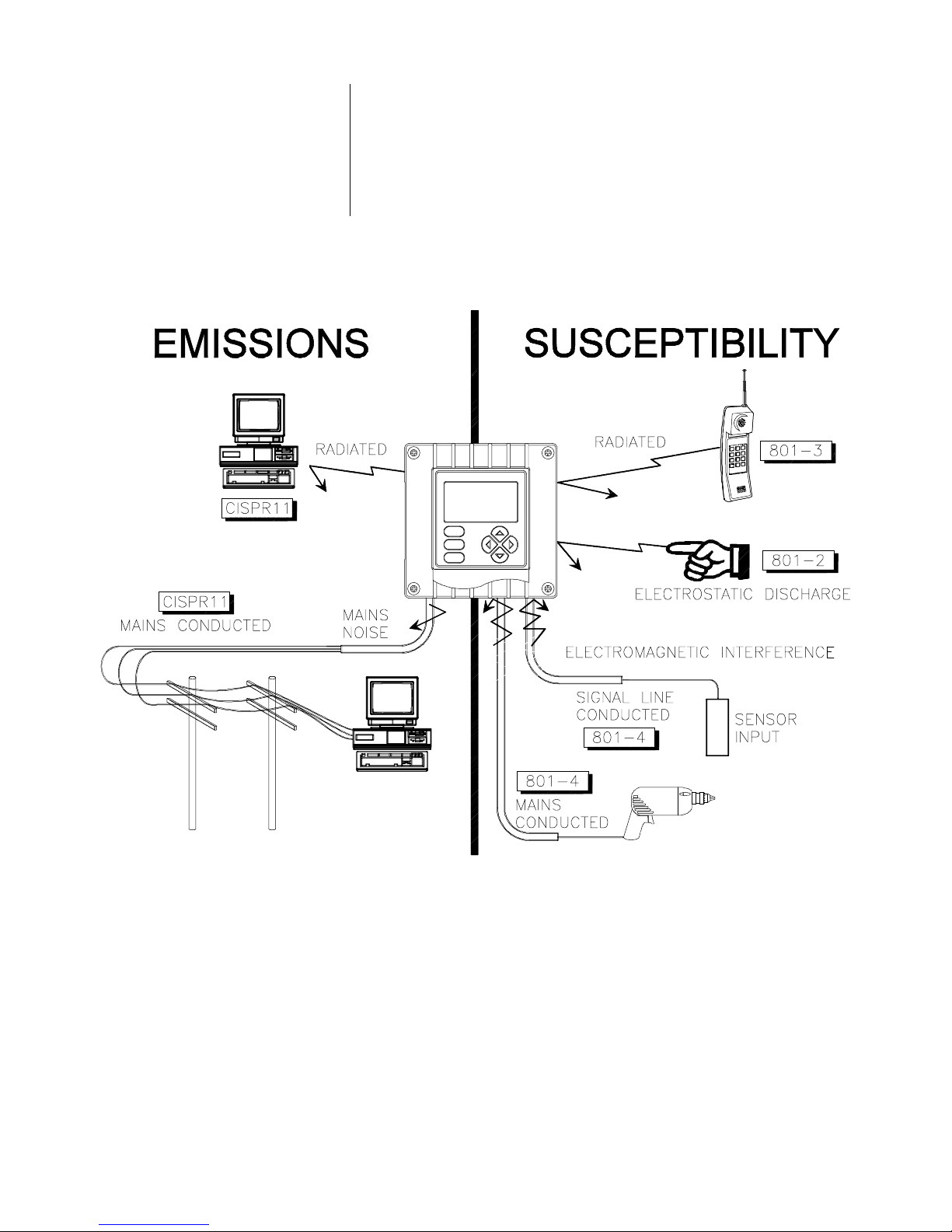
1.5 EMI/RFI Immunity
The analyzer is designed to provide protection from most
normally encountered electromagnetic interference. This
protection exceeds U.S. standards and meets European
IEC 801-series testing for electromagnetic and radio frequency emissions and susceptibility. Refer to Figure 1-1
and the specifications in Section 2.2 for more information.
Accu4™ Low-range Turbidimeter System Rev. 2-300
FIGURE 1-1 EMI/RFI Immunity Diagram
16

PART ONE - INTRODUCTION SECTION 2 - SPECIFICATIONS
ECTION
S
2
SPECIFICATIONS
2.1 Model 8320 Low-range
Turbidity Sensor
Operational
Mechanical
2.2 Model T53 Analyzer
Operational
Flow Rate................................... 0.05 to 7 GPM (0.19 to 26.5 LPM)
Ambient Conditions .................... 32-140°F (0-60°C)
Sample Temperature Range....... 32-140°F (0-60°C)
Pressure Range:
Standard Sensor Design........ 0-50 psig at 68°F (0-3.4 bar at 20°C)
High Pressure Design............ 0-150 psig at 68°F (0-10.2 bar at 20°C)
Pressure Drop:
Standard Sensor Design........ 0.0017 psig at 0.1 GPM (0.0001 bar at 0.36 LPM)
High Pressure Design............ 0.165 psig at 1.0 GPM (0.012 bar at 3.8 LPM)
Residence Time ......................... 9.5 seconds at 1 GPM (3.8 LPM)
Air Venting ................................. Integral bubble trap for 0.05 to 0.5 GPM (0.19 to
1.8 LPM) flows. Installation of restrictor valve on
the sensor outlet is recommended for flows
above 0.5 GPM (1.8 LPM) with air in sample.
Light Sources............................. Two near-infrared (860 nM wavelength) LEDs
Sensor Flow Configuration ......... Flow-through design
Process Connections.................. 1/2 inch NPT female standard; adaptable to
3/8 inch or 1/4 inch NPT, barb or tube fittings
Wetted Materials........................ PVC, polycarbonate, polystyrene, PPO,
nitrile, and Buna-N
Cleaning Method ........................ Water rinse, wipe surfaces
Enclosure:
Standard Sensor Design ....... NEMA 4X (≅ CSA type 4; ≅ IP65), molded and
fiberglass-reinforced polyester (flame retardant)
with four integral tabs for surface mounting
High Pressure Design............ NEMA 4X (≅ CSA type 4; ≅ IP65), PPO struc-
tural foam (V-0 flammability rating per U.L. 94
test) with four integral tabs for surface mounting
Mounting Configurations............. Surface or pipe mount
Net Weight................................. 10 lbs. (4.5 kg) approximately
Display....................................... Graphic dot matrix LCD, 128 x 64 pixels with
LED backlighting; 1/2 inch (13 mm) main
character height; 1/8 inch (3mm) auxiliary
information character height; menu screens
contain up to six text lines
Measurement Auto-ranging Scale
Turbidity................................ 0.000-100.0 NTU with auto-ranging and decimal
point shift above 1.000 NTU and 10.00 NTU
(same for other measurement units)
mA Outputs (1 and 2)............ 0.00-20.00 mA or 4.00-20.00 mA
Rev. 2-300 Accu4™ Low-range Turbidimeter System
Ambient Conditions:
Operation.............................. -4 to +140°F (-20 to +60°C); 0-95% relative
humidity, non-condensing
Storage................................. -22 to +158°F (-30 to +70°C); 0-95% relative
humidity, non-condensing
Relays: Types/Outputs ...................Four electromechanical relays; SPDT (Form C)
contacts; U.L. rated 5A 115/230 VAC, 5A @ 30
VDC resistive
Operational Mode ..............Each relay (A, B, C, and D) can be assigned to be
driven by the measured turbidity or diagnostics
Function Modes:
Control...................... Settings for high/low phasing, setpoint, dead-
band, overfeed timer, off delay, and on delay
17

PART ONE - INTRODUCTION SECTION 2 - SPECIFICATIONS
Alarm ...........................Settings for low alarm point, low alarm point
deadband, high alarm point, high alarm point
deadband, off delay, and on delay
Status....................... Setting for FAIL, WARN or ALL system diag-
nostic conditions to activate relay when
specific conditions exist (analyzer, light source
1/2 or detector 1/2 failure, sensor chamber
dirty or sensor chamber unknown)
Indicators...........................Relay annunciators (A, B, C, and D) indicate
respective relay on/off status
Sensor-to-Analyzer Distance ...... 30 ft. (9 m) maximum (consult factory if
longer distances are required)
Power Requirements .................. 90-130 VAC, 50/60 Hz. (10 VA max.) or
180-260 VAC, 50/60 Hz. (10 VA max.)
Calibration Methods:
PRIMARY............................... Enter one primary standard value (formazin
suspension is recommended).
CUBE CAL ............................. Temporarily insert an optional Cal-Cube
TM
assembly into the sensor and enter its factory-
certified standard value.
SAMPLE................................. Enter one sample value determined by labo-
ratory analysis or calibrated portable meter.
Analog Outputs .......................... Two isolated 0/4-20 mA outputs; each with
0.004 mA (12-bit) resolution and capability to
drive up to 600 ohm loads
NOTE:
Each output represents the measured turbidity. Turbidity values can
be entered to define the endpoints at which the minimum and maximum mA output values are desired. During calibration, both outputs
can be selected to hold their present values, transfer to preset values to operate control elements by an amount corresponding to
those values, or remain active to respond to the measured turbidity.
Communication: RS-232 ........... Enables configuration and retrieval of measured
data for one analyzer using an IBM-compatible
PC and optional GLI software tool kit
HART.............. Enables configuration and retrieval of measured
data for up to 15 analyzers over communication
link using appropriate hand-held terminal or data
system with HART software
Memory Backup (non-volatile) .... All user settings are retained indefinitely in
memory (EEPROM)
EMI/RFI Conformance................ Meets European standards for conducted and
radiated emissions and immunity; certified CE
compliant for applications as specified by EN 50081-1
for emissions and EN 50082-2 for immunity
Electrical Certifications:
General Purpose (pending) ..... UL, C-UL, FM, and CENELEC
Division 2 (pending)................ UL, C-UL, and FM: Groups A, B, C, D, F, and G
Zone 2 (pending) .................... CENELEC: Group IIC
Mechanical
2.3 Accu4™ Turbidimeter
System Performance
(electrical, analog outputs)
Accu4™ Low-range Turbidimeter System Rev. 2-300
Enclosure................................... NEMA 4X; polycarbonate face panel, epoxy-
coated cast aluminum door and case with
four 1/2 inch (13 mm) conduit holes, nylon
mounting bracket, and stainless hardware
Mounting Configurations............. Panel, surface, and pipe mounting
Net Weight................................. 5 lbs. (2.3 kg) approximately
System Accuracy ....................... ± 2% of reading, all ranges
Sensitivity .................................. 0.001 NTU
Repeatability .............................. 0.1% of span or better
Temperature Drift....................... Zero and Span: 0.01% of span per °C
18
PART TW O - INSTALLATION SECTION 1 - UNPACKING
PART TWO - INSTALLATION
ECTION
S
UNPACKING
After unpacking, it is recommended to save the shipping
carton and packing materials in case the instrument must be
stored or re-shipped. Inspect the equipment and packing
materials for signs of shipping damage. If there is any evidence of damage, notify the transit carrier immediately.
ECTION
S
MECHANICAL REQUIREMENTS
1
2
2.1 Sensor Location
Locate the Model 8320 turbidity sensor indoors or outdoors
within 30 ft. (9 m) of where the Model T53 analyzer is to be
installed. The sensor may be installed in an “in line” process
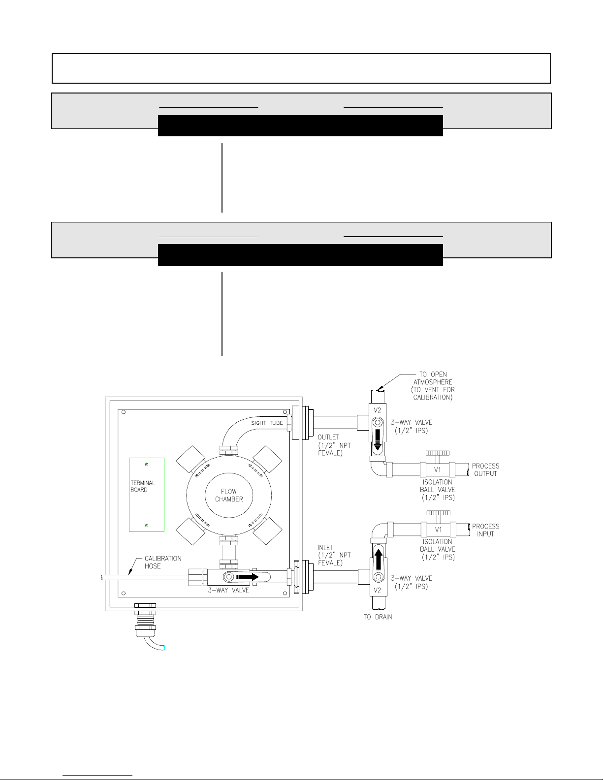
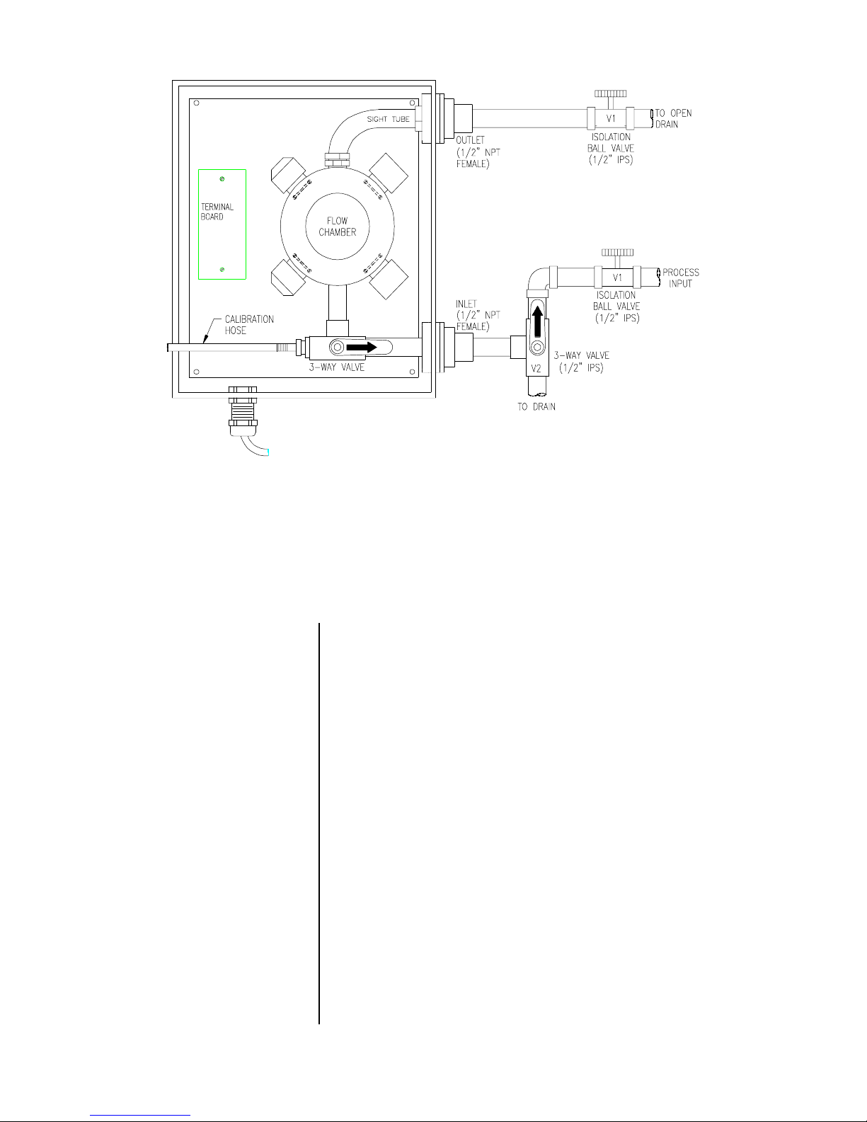
configuration using a closed loop piping arrangement (Figure 2-1) or in a sample bypass line configuration using an
open drain piping arrangement (Figure 2-2).
FIGURE 2-1 Recommended Closed-loop Sensor Piping Arrangement
Rev. 2-300 Accu4™ Low-range Turbidimeter System
19
PART TW O - INSTALLATION SECTION 2 - MECHANICAL REQUIREMENTS
FIGURE 2-2 Recommended Sample Bypass Line Sensor Piping Arrangement
2.2 Sensor Mounting
☞
The Model 8320 low-range turbidity sensor may the standard design sensor (Figure 2-3) or the high pressure design
sensor which is housed in a different enclosure (Figure
2-4). In either case, vertically orient the sensor (inlet fitting
at bottom) and surface mount it where there is little or no
mechanical vibration. Use 1/4 inch screws to fasten the enclosure onto a flat surface. (The sensor may be mounted
onto a vertical or horizontal 1-1/2 inch or 2 inch diameter
pipe using an optional GLI pipe mount kit. Refer to Part Five
-- Spare Parts -- for the GLI part number.
NOTE:
Avoid locations where Model 8320 ambient temperature limits (32-140°F; 0-60°C) may be exceeded.
Accu4™ Low-range Turbidimeter System Rev. 2-300
20

PART TW O - INSTALLATION SECTION 2 - MECHANICAL REQUIREMENTS
Note:
Dimensions shown in inches (mm).
FIGURE 2-3 Standard Design Model 8320 Sensor -- Installation Dimension Details
Note:
Dimensions shown in inches (mm).
FIGURE 2-4 High Pressure Design Model 8320 Sensor -- Installation Dimension Details
Rev. 2-300 Accu4™ Low-range Turbidimeter System
21
PART TW O - INSTALLATION SECTION 2 - MECHANICAL REQUIREMENTS
2.3 Sensor Plumbing
Connections
☞
Plumb the process into the Model 8320 sensor inlet fitting.
Plumb the sensor outlet fitting back into the process line
(Figure 2-1) or to an open drain (Figure 2-2). Bushings may
be used to reduce to a smaller pipe size. Barb or tube fittings may be installed.
sample tubing for applications in which sediment buildup
commonly occurs. The resultant faster flow rate helps flush
sediment through the sensor.
NOTE: Use Teflon tape to seal the inlet and outlet connec-
tions. Do not use pipe dope or other liquid sealants.
Recommendation: Use ball valves (V1 designations in Figure 2-1 and 2-2) to conveniently isolate
the sensor when calibrating or removing the sensor.
In a closed-loop piping arrangement (Figure 2-1),
3-way valves (V2 designations) are required to conveniently drain the flow chamber during calibration.
A bypass line piping arrangement (Figure 2-2) only
requires one 3-way valve.
CAUTION: WHEN USING METAL FITTINGS, DO NOT
EXCESSIVELY TIGHTEN THEM ONTO THE SENSOR’S
PLASTIC INLET AND OUTLET -- THEY MAY CRACK.
Recommendation:
Use larger
☞
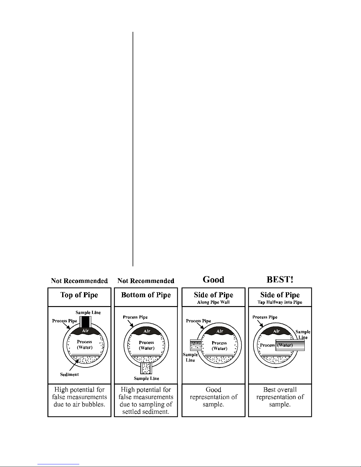
NOTE: When choosing the sampling point for the process
pipe plumbing connection, avoid a top-of-pipe or
bottom-of-pipe location. Figure 2-5 illustrates the
best sampling point location: side-of-pipe with sample line inserted to the process pipe centerline.
Figure 2-5 Sampling Point Guidelines for Process Pipe Plumbing Connection
Accu4™ Low-range Turbidimeter System Rev. 2-300
22
PART TW O - INSTALLATION SECTION 2 - MECHANICAL REQUIREMENTS
2.4 Analyzer Location
2.5 Analyzer Mounting
1. Locate the analyzer as close as possible to the installed
sensor. Do not exceed a maximum distance of 30 feet
(9 m) between the sensor and analyzer. (Consult factory if longer distances are required.)
2. Mount the analyzer in a location that is:
➥
Clean and dry where there is little or no vibration.
➥
Protected from corrosive fluids.
➥
Within ambient temperature limits (-4 to +140°F or
-20 to +60°C).
CAUTION:
EXPOSING THE ANALYZER TO DIRECT
SUNLIGHT MAY INCREASE THE OPERATING
TEMPERATURE ABOVE ITS SPECIFIED LIMIT.
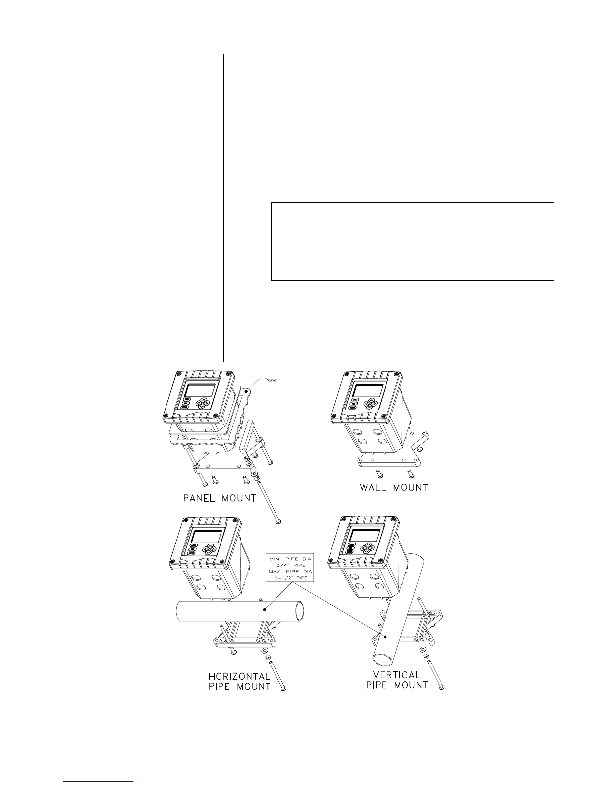
Figure 2-6 illustrates various ways to mount the analyzer
using the supplied bracket and hardware. Determine the
mounting method and attach the hardware as shown in the
respective illustration. Refer to Figure 2-7 for analyzer installation dimension details.
FIGURE 2-6 Analyzer Mounting Arrangements
Rev. 2-300 Accu4™ Low-range Turbidimeter System
23
PART TW O - INSTALLATION SECTION 2 - MECHANICAL REQUIREMENTS
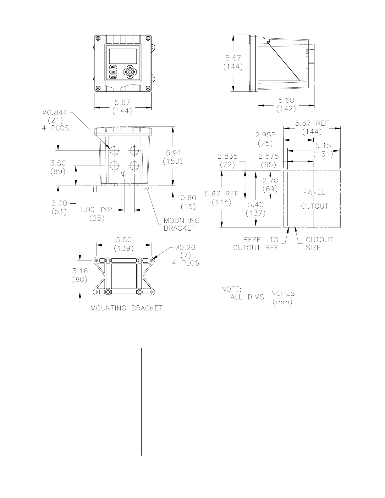
FIGURE 2-7 Analyzer Installation Dimensions Details
2.6 Sensor and Analyzer
Conduit Hole
Requirements
☞
Accu4™ Low-range Turbidimeter System Rev. 2-300
Recommendation:
lyzer in 1/2-inch, grounded metal conduits. If using only
shielded cables, appropriate strain reliefs or cable grips are
required. (GLI sells accessory cable grips, part number
3H1091, and watertight locknuts, part number 3H1230, for
cable entries.) Seal unused cable entry holes with appropriate plugs.
NOTE:
Use NEMA 4 (≅ CSA type 4; ≅ IP65) rated fittings
Run all wiring to the sensor and ana-
and plugs to maintain the watertight integrity of the
NEMA 4X sensor and analyzer enclosures, and to
comply with Div. 2 hazardous area requirements.
24

PART TW O - INSTALLATION SECTION 3 - ELECTRICAL CONNECTIONS
ECTION
S
ELECTRICAL CONNECTIONS
To access terminal blocks for electrical connections, open
the left-hinged enclosure door by unscrewing the four fasteners. Figure 2-8 or 2-9 shows the terminal block
arrangement and terminal designations inside the analyzer.
3
☞
☞
☞
NOTE: All terminals are suitable for single wires up to 14
AWG (2.5 mm2).
Wiring Tip!
electromagnetic compatibility requirements, follow these
general wiring guidelines:
1. Keep all cable shields as short as possible inside
the analyzer, and connect them to the ground terminals provided. Performance may be improved by
using cable glands that enable the shield to directly
contact the analyzer chassis.
2. Use Steward ferrite 28 B0590-000 or equivalent on
the sensor cable -- two turns required.
3. In harsh conducted RF conditions, connect the earth
ground of the analyzer to a local, known earth
ground source.
NOTE: For ease of wiring, route line power and relay out-
To comply with European Community (CE)
puts through the back conduit holes, and use the
front conduit holes for all other wiring.
3.1 GLI Model 8320
Low-range
Turbidity Sensor
☞
☞
Rev. 2-300 Accu4™ Low-range Turbidimeter System
The Model 8320 sensor is supplied with LED light source
and detector cables connected to its terminal board. Remove its protective cover to check that these cables have
not been accidentally disconnected during shipment (refer
to wiring diagram on inside of sensor enclosure door).
Wiring Tip!
grounded metal conduit to protect it from moisture,
electrical noise, and mechanical damage.
NOTE: Do not route sensor cable in any conduit containing
AC power wiring (“electrical noise” may interfere
with sensor signal). Also, always re-calibrate the
system when the cable length between sensor and
analyzer changes.
Route the sensor cable in 1/2-inch,
25
PART TW O - INSTALLATION SECTION 3 - ELECTRICAL CONNECTIONS
OUTPUT 2
RELAY A
NC COM
RS-232
TX RX
NO
3312 5476
4-20 mA
OUTPUT 1
-+-
+
HART
234567
TB2
TURBIDITY INTERCONN ECT
TTL
+
GND
GND
ORANGE
2189 2210 1920 1618
TURBIDITY ANA LYZER
RELAY B
RELAY C
COMNC NCNO
POWER
90-130 VAC
180-260 VAC
10VA 50/60 Hz
COM
8
BLUE
BROWN
F
80mA
T
WHITE
F
2
100mA
T
VIOLET
GREEN
131415 12
115230 N
RED
YELLOW
1
BLACK
GRAY
RELAY D
NCNO NOCOM
1091211 342
TB1
TB3
FIGURE 2-8 Terminal Block Designations for Analyzers with “B” Prefix Serial Number
7% 785%,',7< 6(1625 +22.83
5('
6+,(/'
9,2/(7
:+,7(
*5((1
6+,(/'
<(//2:
%/8(
*5$<
%/$&.
%52:1
7/
25$1*(
FIGURE 2-9 Terminal Block Designations for Analyzers with No Letter Prefix Serial Number
Accu4™ Low-range Turbidimeter System Rev. 2-300
26
PART TW O - INSTALLATION SECTION 3 - ELECTRICAL CONNECTIONS
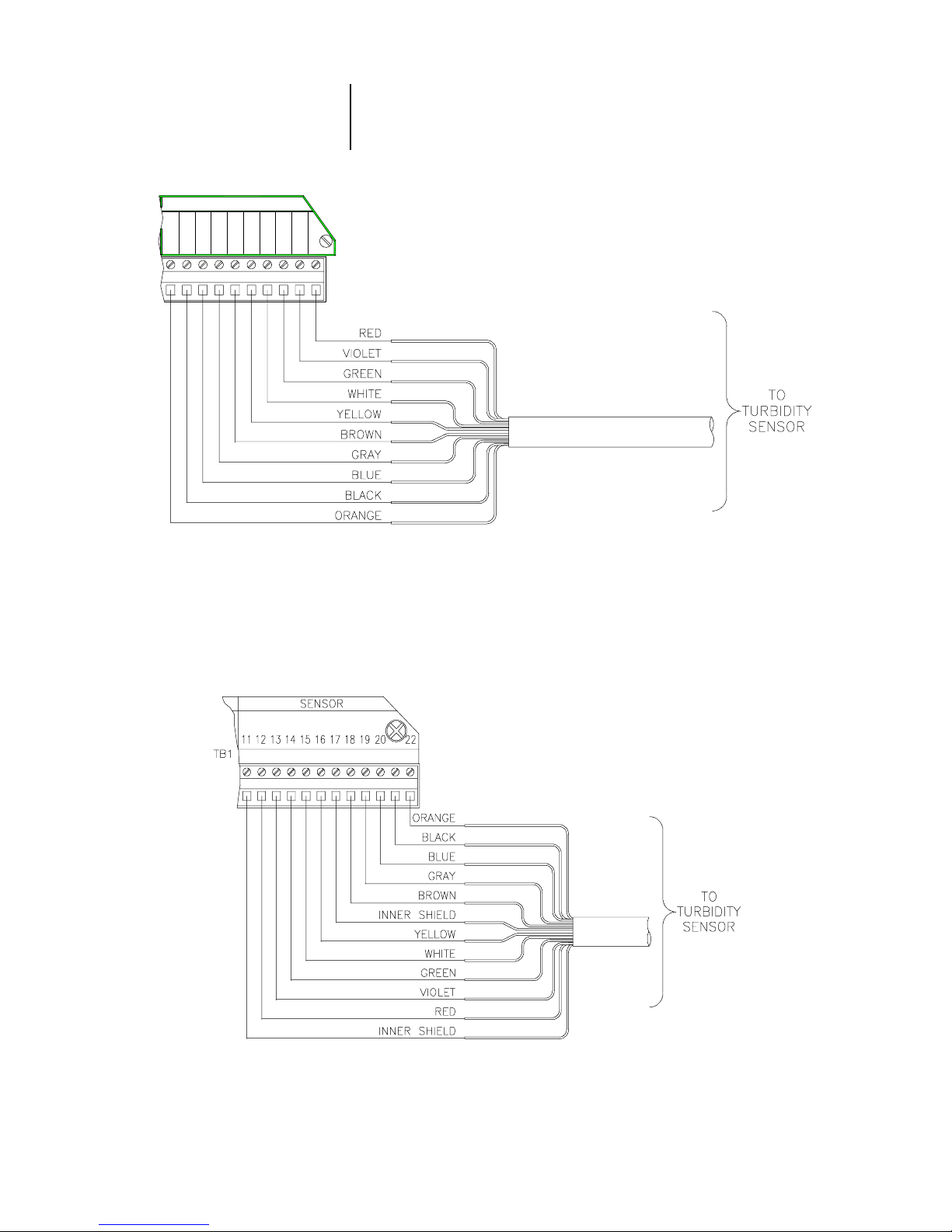
Refer to Figure 2-10 or 2-11 and connect the sensor (or interconnect) cable wires to appropriate terminals on TB1,
matching colors as indicated.
TURBIDITY INTERCONNECT
TB1
BLUE
BLACK
ORANGE
2122 1920 1618
GRAY
BROWN
YELLOW
VIOLET
WHITE
GREEN
RED
131415 12
FIGURE 2-10 Connecting Model 8320 Low-range Turbidity Sensor
to Analyzers with “B” Prefix Serial Number
FIGURE 2-11 Connecting Model 8320 Low-range Turbidity Sensor
to Analyzers with No Letter Prefix Serial Number
Rev. 2-300 Accu4™ Low-range Turbidimeter System
27
PART TW O - INSTALLATION SECTION 3 - ELECTRICAL CONNECTIONS
3.2 Analog Outputs
☞
Two isolated analog outputs (1 and 2) are provided. Each
output represents the measured turbidity, and can be set to
be 0/4-20 mA.
and earth ground, but not from each other.
configuring the outputs, refer to Part Three, Section 4.3.
Wiring Tip!
cable for connecting the analog outputs. To protect the
output signal from EMI/RFI, connect cable shields to:
The grounding strip at bottom of case (5 open holes,
Fig. 2-8) for analyzers with “B” prefix serial number.
The “ground symbol” Terminal 1 on TB1 (Figure 2-9)
for analyzers with no letter prefix serial number.
Each 0/4-20 mA output can drive a load of up to 600 ohms.
• Output 1: Connect the load to Terminals 2 and 3 on TB1,
matching polarity as indicated.
The outputs are isolated from the inputs
For details on
Use high quality, shielded instrumentation
3.3 Relay Outputs
☞
• Output 2: Connect the load to Terminals 4 and 5 on TB1,
matching polarity as indicated.
NOTE: When using the HART communication option, a
digital signal is encoded onto the 4-20 mA analog
Output 1 signal. In a HART SINGLE MODE wiring
configuration, Output 1 remains available for normal
use. However, in a HART MULTI-DROP wiring configuration, Output 1 becomes dedicated to that
function and cannot be used. See Part Three, Section 8 for more HART communication information.
The analyzer is equipped with four electromechanical relays. For relay setup details, see Part Three, Section 4.4.
CAUTION:
DO NOT EXCEED THE CONTACT RATING FOR
EACH RELAY (5A 115/230 VAC). WHEN SWITCHING
LARGER CURRENTS, USE AN AUXILIARY RELAY
SWITCHED BY THE ANALYZER RELAY TO EXTEND
ANALYZER RELAY LIFE. WHEN USING RELAY
OUTPUTS, MAKE SURE THAT LINE POWER WIRING
CAN ADEQUATELY CONDUCT THE CURRENT
DRAW OF THE SWITCHED LOAD(S).
Accu4™ Low-range Turbidimeter System Rev. 2-300
28

PART TW O - INSTALLATION SECTION 3 - ELECTRICAL CONNECTIONS
Four sets of SPDT relay outputs (Relays A, B, C, and D) are
provided at Terminals 1 through 12 on TB2.
puts are not powered.
The line power used to power the
The relay out-
analyzer may also be used to power the control or alarm
devices with these relay contacts. Refer to Figure 2-12 for a
general wiring arrangement. Always check control wiring to
insure that line power will not be shorted by the relay
switching action, and that wiring conforms to local codes.
WARNING:
MAKE SURE THAT LINE POWER IS NOT PRESENT
WHILE CONNECTING WIRES TO TB2 RELAY
TERMINALS.
3.4 Closed Contact
TTL Input
Rev. 2-300 Accu4™ Low-range Turbidimeter System
FIGURE 2-12 Connecting Control/Alarm Device(s) to
Electromechanical Relay(s)
The closed contact TTL input feature of the analyzer enables you to conveniently:
•
Hold the analog outputs at their present values.
•
Hold all CONTROL or ALARM relays at their present
on/off states.
To activate holding the analog outputs and relays, remotely
or locally jumper Terminals 9 and 10 on TB1.
29

PART TW O - INSTALLATION SECTION 3 - ELECTRICAL CONNECTIONS
3.5 Line Power
☞
Refer to appropriate figures and connect line power to TB3
terminals using the standard three-wire connection arrangement.
codes
U.S.A.).
REMOVE LINE POWER WHILE CONNECTING LINE
POWER WIRES TO THE TB3 TERMINALS. ALSO,
USE ONLY THE STANDARD THREE-WIRE CONNECTION ARRANGEMENT FOR SINGLE-PHASE LINE
POWER TO PREVENT AN UNSAFE CONDITION, AND
TO ENSURE PROPER ANALYZER OPERATION.
Use wiring practices which conform to local
(example: National Electric Code Handbook in the
WARNING:
NOTE: In all cases, connect the line power cable ground
wire (usually green) to:
The grounding strip at bottom of case (5 open
holes -- Figures 2-13, 2-15, or 2-17) for analyzers with “B” prefix serial number.
☞
115230 N
342
The “ground symbol” Terminal 1 on TB3 (Figures
2-14, 2-16, or 2-18) for analyzers with no letter
prefix serial number.
The “115” and “230” voltage circuits are protected with internal, board-mounted slow-blow fuses.
NOTE: For 230 volt split phase line power, be sure to con-
form to local codes with regard to fusing the 115
volt line connected to the “N” terminal.
FIGURE 2-13
Connecting 115 V Single Phase
to Analyzers with “B” Prefix Serial Number
Accu4™ Low-range Turbidimeter System Rev. 2-300
FIGURE 2-14
Connecting 115 V Single Phase
to Analyzers with No Letter Prefix Serial Number
30

PART TW O - INSTALLATION SECTION 3 - ELECTRICAL CONNECTIONS
230 115 N
234
FIGURE 2-15
Connecting 230 V Single Phase
to Analyzers with “B” Prefix Serial Number
N115230
234
FIGURE 2-17
Connecting 230 V Split Phase
to Analyzers with “B” Prefix Serial Number
FIGURE 2-16
Connecting 230 V Single Phase
to Analyzers with No Letter Prefix Serial Number
FIGURE 2-18
Connecting 230 V Split Phase
to Analyzers with No Letter Prefix Serial Number
Rev. 2-300 Accu4™ Low-range Turbidimeter System
31

PART THREE - OPERATION SECTION 1 - USER INTERFACE
PART THREE - OPERATION
ECTION
S
USER INTERFACE
The user interface consists of an LCD display and a keypad
MENU, ENTER, ESC
with
1
,
ÕÕ,
ÖÖ,
××, and
ØØ keys.
1.1 Display
By using the keypad, you can display three basic types of
screens:
• MEASURE screen to show measured values. The meas-
ured turbidity is always shown on the display’s main
middle line. Pressing the
play’s bottom auxiliary line (in reverse video) to show the
Analog Output 1 or 2 value in mA.
An example of a typical MEASURE screen is:
On the MEASURE screen’s top line, Relay A, B, C, and D
annunciators will appear when their relay operational
state changes. When a relay overfeed timer is used and it
has “timed out,” the respective relay annunciator continuously blinks until the overfeed condition is resolved.
• MENU screens to move within the three main branches of
the analyzer menu tree, enabling access to edit/selection
screens. (EXIT screens indicate the end of a menu
branch and enable you, by pressing the ENTER key, to
move up one level in the menu tree. This is functionally
the same as pressing the ESC key.)
ØØ and
×× keys changes the dis-
1.2 Keypad
Accu4™ Low-range Turbidimeter System Rev. 2-300
• Edit/Selection screens to enter values/choices to cali-
brate, configure, and test the analyzer.
The keypad enables you to move throughout the analyzer
menu tree. The keys and their related functions are:
1. MENU key: Pressing this key always displays the top of
the menu tree (“MAIN MENU” selection screen). To
display the top-level menu screen for a desired main
branch (CALIBRATE, CONFIGURE, or TEST/MAINT),
use
ØØ and
×× keys to select the corresponding line, and
32

PART THREE - OPERATION SECTION 1 - USER INTERFACE
press
ENTER key
. The
MENU key
can also be used to
“abort” the procedure to change values or selections.
ENTER key:
2.
Pressing this key displays an available
menu or edit/selection screen, or enters (saves) values
or selections.
ESC key:
3.
Pressing this key always takes the display up
one level in the menu tree. (Example: With the “MAIN
MENU” branch selection screen displayed, pressing the
ESC key
once takes the display up one level to the
MEASURE screen.) This key can also “abort” the procedure to change a value or selection.
4.
and
Õ
Õ
keys:
Ö
Ö
Depending on the type of displayed
screen, these keys do the following:
•
MEASURE Screen: These keys are non-functional.
•
Menu Screens: These keys are non-functional.
•
Edit/Selection Screens: “Coarse” adjusts the
displayed numerical value.
5.
and
×
×
keys:
Ø
Ø
Depending on the type of displayed
screen, these keys do the following:
•
MEASURE Screen: Changes the bottom auxiliary
display line, shown in reverse video, between Output
1 mA value and Output 2 mA value.
•
Menu Screens: Moves reverse video cursor up or
down respectively to select a displayed line item.
•
Edit/Selection Screens: “Fine” adjusts the displayed
numerical value (holding key down changes value
faster), or moves up or down between choices.
Rev. 2-300 Accu4™ Low-range Turbidimeter System
FIGURE 3-1 Analyzer Keypad
33

PART THREE - OPERATION SECTION 1 - USER INTERFACE
1.3 MEASURE Screen
(normal display mode)
The MEASURE screen is normally displayed. Pressing the
MENU key
screens to calibrate, configure, or test the analyzer. If the
keypad is not used within 30 minutes, except during calibration and while using specific analyzer test/maintenance
functions, the display automatically returns to the MEASURE screen. To display the MEASURE screen at any time,
press the
When viewing the MEASURE screen, you can press the
or
keys
×
×
the bottom auxiliary display line. These MEASURE screen
examples illustrate this feature:
temporarily replaces this screen with various
MENU key
to select between other measurements shown on
once and then the
ESC key
once.
Ø
Ø
☞
NOTE: When the analyzer returns to its normal MEASURE
screen mode, the appearing MEASURE screen is
always the version last selected. Note that these
MEASURE screen examples show “BASIN 1” nota-
tions on their top lines, illustrating the analyzer
notation feature. To create your own notation, refer
to Part Three, Section 4.2, under the subheading
“ENTER NOTE (top line of MEASURE screen).”
When a measured value is beyond the analyzer measuring
range, a series of “ + ” or “ - ” screen symbols appear, respectively indicating that the value is above or below range.
Accu4™ Low-range Turbidimeter System Rev. 2-300
34

PART THREE - OPERATION SECTION 2 - MENU STRUCTURE
ECTION
S
MENU STRUCTURE
The analyzer menu tree is divided into three main branches:
CALIBRATE, CONFIGURE, and TEST/MAINT. Each main
branch is structured similarly in layers with top-level menu
screens, related lower-level submenu screens and, in many
cases, sub-submenu screens.
Each layer contains an EXIT line or screen to return the
display up one level to the previous layer of screens. For
convenience, the layers within each main branch are organized with the most frequently used functions at their
beginning, rather than the functions used for initial startup.
2
2.1 Displaying
Main Branch
Selection Screen
2.2 Displaying
Top-level
Menu Screens
Press the
selection screen:
1. After displaying the main branch selection screen, use
the
the desired branch (shown in reverse video).
2. Press the ENTER key to display the top-level menu
screen for that branch.
The top-level menu screens for each main branch are:
MENU key
ØØ and
to always display this main branch
&21),*85(
7(670$,17
(;,7
×× keys to select the line corresponding to
☞
Rev. 2-300 Accu4™ Low-range Turbidimeter System
Menu Structure Tip! The symbol pointing at each listed
item indicates there is a related lower-level submenu
screen, sub-submenu screen or edit/selection screen.
Some menu lists are too long to completely fit on the
screen. A
ÈÈ symbol at the bottom right of the list indicates
35

PART THREE - OPERATION SECTION 2 - MENU STRUCTURE
2.3 Displaying
Submenu Screens
☞
or
Ø
Ø
Ø
Ø
that you can display hidden items by pressing the
key
. As you display these items a ↕ symbol appears, indicating that items now hidden above and below the list
can be displayed by respectively pressing the
key
. When a
reached the end of the menu list. You can move back up
the list using the
ÇÇ symbol appears, it indicates you have
×× key.
×
×
NOTE: The symbol pointing at a listed menu item indi-
cates that this item is not relevant to, nor required
for, the previously entered setup choices and,
therefore, is not available.
1. After displaying the top-level menu screen, use the
ØØ and
desired lower-level submenu screen.
2. Press the ENTER key to display the submenu screen.
×× keys to select the line corresponding to the
2.4 Adjusting
Edit/Selection
Screen Values
When a submenu or sub-submenu screen contains a first
line ending with a “?,” it is an edit/selection screen. Pressing
the
ØØ or
×× key changes the value/choice enclosed by pa-
renthesis (second line on screen).
Example: With this submenu edit screen displayed:
pressing the
Edit/selection screens always contain a second line enclosed by parenthesis -- see examples shown above and
below. The enclosed value/choice can be edited/changed
by using the
saves the change.
×× and
ØØ key displays this related choice:
ØØ keys. Pressing the ENTER key
Accu4™ Low-range Turbidimeter System Rev. 2-300
Use the
The
×× and
ÕÕ and
ÖÖ keys to “coarse” adjust numerical values.
ØØ keys “fine” adjust numerical values up or
36

PART THREE - OPERATION SECTION 3 - ADJUSTING DISPLAY CONTRAST
down respectively. The longer the key is pressed, the faster
the number changes.
2.5 Entering (Storing)
Edit/Selection Screen
Values/Choices
After the desired value/choice is displayed, press the
ENTER key
memory. The previous screen will then re-appear.
NOTE: You can always press the ESC key to abort saving
☞
S
ADJUSTING DISPLAY CONTRAST
Ambient lighting conditions may make it necessary to adjust
the analyzer display contrast to improve visibility. With the
MEASURE screen displayed, press and hold the
key
and simultaneously press the
the desired contrast.
to enter (store) it into the non-volatile analyzer
a new setting. The original setting will be retained.
ECTION
3
×
×
or
Ø
Ø
key
until attaining
ENTER
Rev. 2-300 Accu4™ Low-range Turbidimeter System
37

PART THREE - OPERATION SECTION 4 - CONFIGURING THE ANALYZER
ECTION
S
CONFIGURING THE ANALYZER
4
☞
4.1 Selecting LANGUAGE
to Operate Analyzer
NOTE: When the passcode feature is enabled (Section
4.5), you must successfully enter the passcode
before attempting to enter a configuration setting.
The analyzer can display screens in various languages including English, French (Français), German (Deutsche),
Spanish (Español), and others. The analyzer is factory-set
for English. To change languages:
&21),*85(
7(670$,17
(;,7
1. Press
key to select the “CONFIGURE” line.
2. Press ENTER key to display . Use
ØØ key to select the “LANGUAGE” line.
MENU key
to display
. Use
Ø
Ø
4.2 Configuring
Sensor Characteristics
SELECT UNITS
☞
3. Press ENTER key to display a screen like
. Use
guage choices.
4. With the desired language displayed, press ENTER
key to enter this selection.
NOTE: After a language is selected and entered, all
screens will be displayed in that language.
You may want to configure the analyzer to define related
sensor characteristics such as units of measure, input signal filtering, pulse suppression, and a MEASURE screen
top line notation to specifically tailor the instrument to your
application.
The Accu4™ Low-range Turbidimeter System is factory
set to display turbidity in NTUs. However, you may want
to select different measurement units:
ØØ and
×× keys to view the lan-
Accu4™ Low-range Turbidimeter System Rev. 2-300
38

PART THREE - OPERATION SECTION 4 - CONFIGURING THE ANALYZER
key
1. With the screen displayed, use
Ø
Ø
to select the “SENSOR” line.
SET FILTER Time
2. Press
3. With the “SELECT UNITS” line selected, press
key
and
4. With the desired choice displayed value, press
key
ENTER key
to display .
ENTER
to display a screen like . Use
keys
×
×
•
NTU (Nephelometric Turbidity Units)
•
FTU (Formazin Turbidity Units
•
FNU (Formazin Nephelometric Units)
•
TEF (TruebungsEinhelt Formazin -- a German unit)
to view all choices which are all equivalent:
ENTER
to enter this selection.
Ø
Ø
A time constant (in seconds) can be set to filter or “smooth
out” the sensor signal. A minimum value of “0 seconds” has
no smoothing effect. A maximum value of “60 seconds” provides maximum smoothing. Deciding what sensor signal
filter time to use is a compromise. The higher the filter time,
the longer the sensor signal response time will be to a
change in the actual turbidity value.
Rev. 2-300 Accu4™ Low-range Turbidimeter System
key
1. With the screen displayed, use
Ø
Ø
to select the “SET FILTER” line.
2. Press
ENTER key
to display a screen like
.
3. Adjust the displayed value to the desired filter time, and
press
keys
ENTER key
for coarse adjust;
39
to enter the value. (Use
and
×
×
keys
Ø
Ø
for fine adjust.)
and
Ö
Ö
Õ
Õ

PART THREE - OPERATION SECTION 4 - CONFIGURING THE ANALYZER
Select
PULSE SUPPRESS
(on/off)
Sometimes an external interference may occasionally cause
the measurement system to provide unstable readings.
Common causes include entrained gas bubbles in the sample, and electromagnetic interference (EMI or “electrical
noise” pulses). The analyzer has a pulse suppression feature to counteract this condition and stabilize readings.
Example: Suppose the analyzer reading is steadily showing
0.284 NTU, then suddenly jumps to 0.396 NTU for a few
seconds, and returns to 0.284 NTU. By turning on this feature, the analyzer will perceive this as a temporary upset,
“suppressing” most of this pulse change and providing a
smoother measurement reading.
key
1. With the screen displayed, use
Ø
Ø
to select the “PULSE SUPPRESS” line.
2. Press
ENTER key
. Use
to display a screen like
and
Ø
Ø
keys
×
×
to view both
choices (OFF or ON).
ENTER NOTE (top line
of MEASURE screen)
3. With the desired choice displayed, press
ENTER key
to
enter this selection.
The MEASURE screen top line is factory set to read “ACCU4.”
This notation can be changed, for example, to “BASIN 1” to
tailor the MEASURE screen to the application. The notation is
limited to eight characters which can be a combination of
capital letters A through Z, numbers 0 through 9, and spaces.
key
1. With the screen displayed, use
Ø
Ø
to select the “ENTER NOTE” line.
2. Press
ENTER key
to display . Create
the desired notation within second line’s parenthesis:
A. Starting with extreme left character position, use
and
keys
Ø
Ø
to select the desired first character.
×
×
Accu4™ Low-range Turbidimeter System Rev. 2-300
key
B. Press
use
Ö
and
×
×
Ö
once to select the next character, and
keys
Ø
Ø
to select desired character.
C. Repeat procedure until desired notation is displayed.
3. Press
ENTER key
40
to enter the displayed notation.

PART THREE - OPERATION SECTION 4 - CONFIGURING THE ANALYZER
4.3 Configuring Analog
Outputs (1 and 2)
☞
The analyzer provides two isolated analog outputs (1 and
2), each representing the measured turbidity. During calibration, both analog outputs can be held at their present
values, transferred to a preset value, or remain active. During normal measurement operation, both outputs can be:
•
Held for up to 30 minutes by using the “CHECK CAL/
HOLD” function in the TEST/MAINT menu.
•
Held indefinitely by locally or remotely connecting both
TTL input terminals on TB1.
If a TEST/MAINT hold is applied in addition to a TTL hold,
both “holds” must be removed before the outputs return to
active status. If the outputs are set to “XFER” or “ACTIVE”
during a calibration, they remain in that state until after calibration regardless of the TTL input status.
NOTE: When using the HART communication option, a
digital signal is encoded onto the 4-20 mA analog
Output 1 signal. In a HART SINGLE MODE wiring
configuration, Output 1 remains available for normal
use. However, in a HART MULTI-DROP wiring configuration, Output 1 becomes dedicated to that
function and cannot be used. See Part Three, Section 8 for more HART communication information.
SET 0/4 and
20 mA VALUES
These instructions configure Output 1. Configure Output 2 in the same way using its respective menu
screens.
You can set the turbidity values to define the endpoints at
which the minimum and maximum output values are desired.
1. With the top-level menu screen displayed and the “SET OUTPUT 1” line selected, press
ENTER key
to display
.
Rev. 2-300 Accu4™ Low-range Turbidimeter System
41

PART THREE - OPERATION SECTION 4 - CONFIGURING THE ANALYZER
2. With the “SET 4 mA VALUE” line selected, press
☞
ENTER key
3. Set the displayed value at which 0/4 mA is desired, and
press
keys
for coarse adjust;
4. After the screen re-appears, use
to select the “SET 20 mA VALUE” line.
5. Press
6. Set the displayed value at which 20 mA is desired, and
press
ENTER key
to display a screen like .
ENTER key
ENTER key
to enter the value. (Use
and
×
×
to display a screen like
.
to enter the value.
keys
Ø
Ø
for fine adjust.)
and
Ö
Ö
Ø
Ø
Õ
Õ
key
NOTE: If the same values are set for 0/4 mA and 20 mA, the
output automatically goes to, and remains at, 20 mA.
SET TRANSFER
Value (mA)
Normally, each analog output is active, responding to the
measured turbidity value. During calibration, however, you
can transfer (XFER) each output to a preset value to operate a control element by an amount corresponding to that
value.
If you desire to set a milliamp transfer value for an analog
output to suit your application, follow these steps:
key
1. With the screen displayed, use
to select the “SET TRANSFER” line.
2. Press
3. Set the displayed value to the desired transfer value,
and press
for coarse adjust;
ENTER key
.
ENTER key
and
×
×
to display a screen like
and
to enter it. (Use
keys
Ø
Ø
for fine adjust.)
Ö
Ö
Ø
Ø
keys
Õ
Õ
Accu4™ Low-range Turbidimeter System Rev. 2-300
42

PART THREE - OPERATION SECTION 4 - CONFIGURING THE ANALYZER
SET FILTER Time
☞
A time constant (in seconds) can be set to filter or “smooth
out” the output signal. A minimum value of “0 seconds” has
no smoothing effect. A maximum value of “60 seconds” provides maximum smoothing. Deciding what output filter time
to use is a compromise. The higher the filter time, the longer
the output signal response time will be to a change in the
measured turbidity.
NOTE: The output filter time setting combines with the sen-
sor signal filter time setting, providing an additive
delay in output response to the actual reading.
key
1. With the screen displayed, use
to select the “SET FILTER” line.
2. Press
ENTER key
.
to display a screen like
Ø
Ø
Select SCALE 0 mA/
4 mA (low endpoint)
3. Adjust the displayed value to the desired filter time, and
press
coarse adjust;
Select each output to be 0-20 mA or 4-20 mA.
1. With the screen displayed, use
to select the “SCALE 0mA/4mA” line.
2. Press
Ø
Ø
3. With the desired choice displayed, press
enter this selection.
ENTER key
ENTER key
and
×
×
to enter it. (Use
and
×
×
keys
to view both choices (0 mA or 4 mA).
keys
Ø
Ø
to display . Use
for fine adjust.)
and
Ö
Ö
ENTER key
keys
Õ
Õ
Ø
Ø
for
key
to
Rev. 2-300 Accu4™ Low-range Turbidimeter System
43

PART THREE - OPERATION SECTION 4 - CONFIGURING THE ANALYZER
4.4 Configuring Relays
(A, B, C, and D)
The analyzer is equipped with four electromechanical relays
(A, B, C, and D). Each relay can be set to function as a
CONTROL, ALARM, or STATUS relay. For details on each
relay function, see subsection “SET FUNCTION Mode.”
During calibration, CONTROL and ALARM (not STATUS)
relays can be held at their present on/off states, transferred
to preset on/off states, or remain active. During normal
measurement operation, CONTROL and ALARM relays can
be:
•
Held at their present on/off states for up to 30 minutes
by using the “CHECK CAL/HOLD” function in the TEST/
MAINT menu.
•
Held at their present on/off states indefinitely by locally
or remotely connecting both TTL input terminals on
TB1.
If a TEST/MAINT hold is applied in addition to a TTL hold,
both “holds” must be removed before CONTROL and
ALARM relays return to active status. If the relays are set to
“XFER” or “ACTIVE” during a calibration, they remain in that
state until after calibration regardless of the TTL input
status.
SET FUNCTION Mode
(alarm, control, or status)
These instructions configure Relay A. Configure other
relays in the same way using their respective menu
screens.
Each relay can be selected to function as a:
ALARM
•
relay (with separate high and low alarm points
and deadbands) that operates in response to the
measured turbidity.
CONTROL
•
relay (with phasing, setpoint, deadband,
and overfeed timer) that operates in response to the
measured turbidity.
STATUS
•
relay that operates only in response to
selected system diagnostic conditions. It can be
configured for:
FAIL mode -- sets STATUS relay to activate when
there is a FAIL condition (analyzer, light source or
detector) or a sensor CHAMBER UNKNOWN
condition.
Accu4™ Low-range Turbidimeter System Rev. 2-300
44

PART THREE - OPERATION SECTION 4 - CONFIGURING THE ANALYZER
WARN mode -- sets STATUS relay to activate only when
there is a sensor flow CHAMBER DIRTY condition.
ALL mode -- sets STATUS relay to activate when
there is any abnormal system condition (any FAIL
condition, or sensor CHAMBER DIRTY or
UNKNOWN condition).
A “WARNING CHECK STATUS” message automatically
flashes on the MEASURE screen whenever the analyzer
detects any of these system diagnostic conditions:
•
ANALYZER FAIL
•
CHAMBER DIRTY
•
CHAMBER UNKNOWN• DETECT 2 FAIL
•
SOURCE 1 FAIL
•
SOURCE 2 FAIL
•
DETECT 1 FAIL
To determine the condition causing the warning message,
display the “STATUS” screens in the TEST/MAINT menu
branch. For more details, see Part Three, Section 6.1.
Relay D is factory-set to function as a STATUS relay but
can be configured as a CONTROL or ALARM relay.
1. With the screen displayed, press
key
once to display .
ESC
Rev. 2-300 Accu4™ Low-range Turbidimeter System
key
2. Use
Ø
Ø
ENTER key
to select the “SET RELAY A” line, and press
to display .
3. With the “SET FUNCTION” line selected, press
key
to display a screen like
and
keys
×
×
to view the choices (ALARM, CONTROL or
. Use
STATUS).
4. With the desired choice displayed, press
ENTER key
enter this selection.
45
ENTER
Ø
Ø
to

PART THREE - OPERATION SECTION 4 - CONFIGURING THE ANALYZER
SET TRANSFER Mode
(relay on or off)
Normally, each CONTROL or ALARM relay is ACTIVE, responding to the measured turbidity. During calibration,
however, you can transfer (XFER) each relay to a preset
on/off state.
If you desire to set a relay on/off transfer state for a
CONTROL or ALARM relay to suit your application, follow
these steps:
key
1. With the screen displayed, use
Ø
Ø
to select the “SET TRANSFER” line.
2. Press
ENTER key
. Use
to display a screen like
and
Ø
Ø
keys
×
×
to view both
choices (DE-ENERGIZED or ENERGIZED).
3. With the desired choice displayed, press
ENTER key
to
enter this selection.
SET ACTIVATION
(configuration values)
The group of configuration settings available to a relay is
dependent on its selected function mode. Table A describes
relay configuration settings, categorized by function mode:
Table A -- RELAY CONFIGURATION SETTINGS
Setting Description
For ALARM Relay
Low Alarm Sets the value at which the relay will turn on in
response to decreasing measured value.
High Alarm Sets the value at which the relay will turn on in
response to increasing measured value.
Low
Deadband
High
Deadband
Off Delay Sets a time (0-300 seconds) to delay the relay from
On Delay Sets a time (0-300 seconds) to delay the relay from
Phase A “high” phase assigns the relay setpoint to respond
Setpoint Sets the value at which the relay will turn on.
Sets the range in which the relay remains on after the
measured value increases above
Sets the range in which the relay remains on after the
measured value decreases below
normally turning off.
normally turning on.
For CONTROL Relay
to increasing measured value; conversely, a “low”
phase assigns the relay setpoint to respond to decreasing measured value.
the low alarm value.
the high alarm value.
Accu4™ Low-range Turbidimeter System Rev. 2-300
46

PART THREE - OPERATION SECTION 4 - CONFIGURING THE ANALYZER
Table A -- RELAY CONFIGURATION SETTINGS -- continued
Setting Description
For CONTROL Relay (continued)
Deadband Sets the range in which the relay remains on after the
measured value decreases below the setpoint value
(high phase relay) or increases above the setpoint
value (low phase relay).
Overfeed
Timer
Off Delay Sets a time (0-300 seconds) to delay the relay from
On Delay Sets a time (0-300 seconds) to delay the relay from
Fail Sets the relay to turn on only when there is a FAIL
Warn Sets the relay to turn on only when there is a sensor
All Sets the relay to turn on when there is any abnormal
Sets the time (0-999.9 min.) to limit how long the relay can remain “on.” For more details on overfeed
timer operation, see Part Three, Section 7.
normally turning off.
normally turning on.
For STATUS Relay
condition (analyzer, light source or detector) or a
sensor CHAMBER UNKNOWN condition.
flow CHAMBER DIRTY condition.
system condition (any FAIL condition, or sensor flow
CHAMBER DIRTY or UNKNOWN condition).
☞
NOTE: Also, it is possible to enter values that always keep
a relay active or inactive. To avoid this, be sure that
“low” values are lower than “high” values.
The “off delay” and “on delay” settings, available to
CONTROL or ALARM relays, may be beneficial in eliminating process “overshoot” when there are long process pipe
runs or delays in mixing.
Suppose Relay A is an ALARM. To set configuration values:
key
1. With the screen displayed, use
Ø
Ø
to select the “ACTIVATION” line.
2. Press
ENTER key
to display
.
Rev. 2-300 Accu4™ Low-range Turbidimeter System
key
3. Use
Ø
Ø
to select the appropriate relay setting line,
and press
edit/selection screen.
47
ENTER key
to display its corresponding

PART THREE - OPERATION SECTION 4 - CONFIGURING THE ANALYZER
4. Use the same basic keypad operations described in
previous setup procedures to enter the desired value
for the displayed relay activation setting.
5. Repeat this procedure for each relay activation setting.
4.5 SET PASSCODE
(feature enabled/
disabled)
The analyzer has a passcode feature to restrict access to
configuration and calibration settings to only authorized
personnel.
DISABLED:
•
With passcode disabled, all configuration
settings can be displayed and changed, and the analyzer
can be calibrated.
ENABLED:
•
With passcode enabled, all configuration settings can be displayed -- but they cannot be changed, and
the analyzer cannot be calibrated. When you attempt to
change a setting by pressing the
ENTER key
, a displayed
notification requests passcode entry. A valid passcode
entry saves the changed setting and returns the display to
the “MAIN MENU” branch selection screen. An incorrect
passcode entry causes the display to momentarily show
an error notification and return to the “MAIN MENU”
branch selection screen. There is no limit on attempts to
enter a valid passcode.
The passcode is factory-set to “
3456
.” It cannot be changed.
To enable or disable the passcode feature:
1. With the top-level menu screen dis-
key
played, use
2. Press
and
Ø
Ø
Ø
Ø
ENTER key
keys
×
×
to view both choices (DISABLED or
to select the “SET PASSCODE” line.
to display . Use
ENABLED).
3. With the desired choice displayed, press
ENTER key
to
enter this selection.
Accu4™ Low-range Turbidimeter System Rev. 2-300
48

PART THREE - OPERATION SECTION 4 - CONFIGURING THE ANALYZER
4.6 Configuration Setting
Summary
Table B -- ANALYZER CONFIGURATION SETTINGS (RANGES/CHOICES and DEFAULTS)
Displayed Screen Title Entry Range or Choices (where applicable) Factory Default Your Setting
LANGU AGE? ENGLISH, FRENCH, GERMAN, SPANISH, etc. ENG L ISH
SET FILTER? 0-60 seconds 30 seconds
PULSE SUPPRESS? OFF or ON OFF
ENTER NOTE? Enter up to eight characters to replace ACCU4 ACCU4
SET 4mA VALUE? 0.000-100.0 NTU 0.000 NTU
SET 20mA VALUE? 0.000-100.0 NTU 100.0 NTU
SET TRANSFER? 0-20 mA or 4-20 mA Outputs 1 and 2: 12 mA
SET FILTER? 0-60 seconds Outputs 1 and 2: 0 seconds
SCALE 0mA/4mA? 0 mA or 4 mA Outputs 1 and 2: 4 mA
Settings Common To ALARM and CONTROL Relays:
SET FUNCTION? ALARM, CONTROL, or STATUS Relays A and B: ALARM
SET TRANSFER? DE-ENERGIZED or ENERGIZED Relays A and B: DE-ENERGIZED
OFF DELAY? 0-300 seconds 0 seconds
ON DELAY? 0-300 seconds 0 seconds
Settings For ALARM Relays Only:
LOW ALARM? 0.000-100.0 NTU 0.000 NTU
HIGH ALARM? 0.000-100.0 NTU 100.0 NTU
LOW DEADBAND? 0-10% of meas. range in which setpoint resides 0.000 NTU
HIGH DEADBAND? 0-10% of meas. range in which setpoint resides 0.000 NTU
Settings For CONTROL Relays Only:
PHASE? HIGH or LOW Relays A and B: HIGH
SET SETPOINT? 0.000-100.0 NTU 100.0 NTU
DEADBAND? 0-10% of meas. range in which setpoint resides 0.000 NTU
OVERFEED TIMER? 0-999.9 minutes 0 minutes
Setting For STATUS Relays Only:
ACTIVATION? FAIL, WARN or ALL STATUS Relays A and B: ALL
SET PASSCODE? DISABLED or ENABLED DISABLED
TEST/MAINTENANCE Simulation Function Setting
SIM SENSOR? 0.000-100.0 NTU Present measured turbidity value
Table B lists all configuration settings and their entry ranges/
choices and factory defaults, categorized by basic functions.
LANGUAGE Configuration Setting
SENSOR Configuration Settings
Analog OUTPUT Configuration Settings
RELAY Configuration Settings
Relay C: STATUS -- WARN
Relay D: STATUS -- FAIL
STATUS Relay C: W ARN
STATUS Relay D: FAIL
PASSCODE Configuration Setting
Rev. 2-300 Accu4™ Low-range Turbidimeter System
49

PART THREE - OPERATION SECTION 5 - CALIBRATING THE ANALYZER
ECTION
S
CALIBRATING THE ANALYZER
5
5.1 Things to Know
About Calibration
☞
The Accu4™ Low-range Turbidimeter System can be calibrated using one of three methods:
•
PRIMARY CAL: Requires entering a primary standard
value of a formazin suspension.
•
CUBE CAL: Requires inserting an optional Cal-Cube
assembly into the sensor flow chamber and entering its
factory-certified standard value.
•
SAMPLE CAL: Requires entering a sample value deter-
mined by laboratory analysis or calibrated portable
meter.
You can conveniently verify system calibration at any
time, regardless of the method used, with the optional
GLI Cal-Cube™ assembly. Refer to Part Three, Section
6.2 for complete details.
NOTE: The sensor is equipped with long-lasting light
sources and detectors. If these components are
eventually replaced, always re-calibrate the system
using the appropriate method to ensure measurement accuracy. Also, re-calibrate if the cable length
between sensor and analyzer changes.
TM
☞
The mA value for each analog output can also be calibrated
(Section 5.5).
NOTE: When the passcode feature is enabled (Section
4.5), you must successfully enter the passcode
before attempting to calibrate the analyzer.
An in-progress calibration can always be aborted by
pressing the ESC key. After the “ABORT: YES?”
screen appears, do one of the following:
•
Press ENTER key to abort. After the “CONFIRM
ACTIVE?” screen appears, press ENTER key to
return the analog outputs and relays to their active states (MEASURE screen appears).
•
Press
screen, and press ENTER key to continue calibration.
×
×
or
Ø
key to choose the “ABORT: NO?”
Ø
Accu4™ Low-range Turbidimeter System Rev. 2-300
50

PART THREE - OPERATION SECTION 5 - CALIBRATING THE ANALYZER
☞
5.2 PRIMARY CAL Method
(requires formazin
suspension)
Calibration Tip!
“CONFIRM FAILURE?” screen appears, press
key
to confirm. Then, use
If at any time during calibration, the
ENTER
or
Ø
Ø
key
to select between
×
×
“CAL REPEAT?” or “CAL EXIT?” and do one of the following:
•
With the “CAL REPEAT?” screen selected, press
ENTER key
•
With the “CAL EXIT?” screen selected, press
key
. After the “CONFIRM ACTIVE?” screen appears,
press
to repeat calibration.
ENTER key
to return the analog outputs and
ENTER
relays to their active states (MEASURE screen appears).
This calibration method requires you to first fill the sensor
flow chamber with a primary standard (formazin suspension) and then enter its known value. Since formazin is the
recommended primary standard, it is used in the instructions for this method.
Preparing
Formazin Solution
Prepare 2000 milliliters of
20 NTU or higher
formazin suspension (USEPA requires 40 NTU to comply with GLI
Method 2) using the following laboratory procedure:
1. Make the dilution water:
To obtain high-purity, low turbidity water for dilutions,
pass distilled water through a 0.2 micron filter. Rinse
the flask at least twice with filtered water before collecting the dilution water.
2. Make the stock turbidity suspension:
WARNING:
HYDRAZINE SULFATE IS A KNOWN
CARCINOGEN. TAKE PRECAUTIONS TO AVOID
INHALATION, INGESTION, AND SKIN CONTACT.
SOLUTION 1:
A.
grade hydrazine sulfate, (NH
Dissolve 5.00 grams of reagent-
2)2H2SO4
, in distilled
water and dilute to 500 ml in a volumetric flask.
Rev. 2-300 Accu4™ Low-range Turbidimeter System
51

PART THREE - OPERATION SECTION 5 - CALIBRATING THE ANALYZER
SOLUTION 2:
B.
Dissolve 50.00 grams of reagent-grade
hexamethylenetetramine, (CH2)6N4, in distilled water
and dilute to 500 ml in a volumetric flask.
C. In a flask, mix 50.0 ml of SOLUTION 1 and 50.0 ml
of SOLUTION 2. Let this mixture stabilize for 24
hours at 25°C, ± 3°C. The resultant mixture is a
4000 NTU stock turbidity suspension. Transfer the
stock suspension to an amber glass (or other UVlight blocking) bottle for storage. Make dilutions
from this stock suspension. When properly stored,
this stock suspension should remain stable for up
to one year.
3. Make the standard formazin suspension for calibration:
20 NTU Standard Suspension:
•
Use filtered dilution water to dilute 10 ml of 4000 NTU stock
suspension to 2000 ml.
☞
Filling Sensor
40 NTU Standard Suspension:
•
Use filtered dilution water to dilute 20 ml of 4000 NTU stock
suspension to 2000 ml.
Calibration Tip!
Use only freshly prepared, properly
stored, and carefully measured formazin suspension.
Formazin tends to flocculate over time, causing inaccurate readings. Formazin suspensions must be equally
distributed within the flask. Gently swirl the flask several
times. Do not vigorously shake the flask which could introduce air bubbles that may falsely increase readings.
Recommendation:
1.
Before filling the sensor with a formazin suspension (primary standard), hold the analyzer
analog outputs at their present values or transfer them
to preset values to ensure a safe condition for any connected devices.
Accu4™ Low-range Turbidimeter System Rev. 2-300
&21),*85(
7(670$,17
(;,7
A. Press
MENU key
to display
.
B. With the “CALIBRATE” line selected (reverse video),
press ENTER key to display .
52

PART THREE - OPERATION SECTION 5 - CALIBRATING THE ANALYZER
C. With the “SENSOR” line selected, press
key
to display .
D. With the “PRIMARY CAL” line selected, press
ENTER key
key
Ø
Ø
puts (and relays) can be in during calibration:
•
•
•
E. With the desired choice displayed, press
key
2. Turn the sensor’s 3-way valve handle to the
CALIBRATE
of the flow chamber (
to view the three states that the analog out-
HOLD OUTPUTS:
XFER OUTPUTS:
ACTIVE OUTPUTS:
to enter this selection.
to display . Use
Holds their present values.
Transfers to preset values.
Responds to measured turbidity.
position as shown by the label at the base
Õ
points towards funnel hose).
Õ
ENTER
or
×
×
ENTER
☞
3. If the recommended isolation valve is used downstream
of the sensor OUTLET, open the valve to atmospheric
pressure to improve draining.
4. Drain any remaining process from the sensor by removing
the funnel from its holder and lowering it below the sensor
height. When drained, replace funnel into holder.
5. Remove the baffle assembly from the flow chamber and
rinse it with clean water.
6. Clean the inside of the flow chamber and the light source
and detector windows with a soft, clean, damp cloth.
7. Re-install the baffle assembly into the flow chamber,
and replace and tighten the flow chamber cover.
NOTE: The following steps 8, 9, and 10 ensure that only
pure, primary standard formazin suspension is being measured in the sensor flow chamber.
Rev. 2-300 Accu4™ Low-range Turbidimeter System
8. Rinse the sensor’s internal tubing with the primary
standard formazin suspension by pouring it into the
funnel until the suspension can be seen in the clear
SIGHT TUBE. Now drain this rinse suspension in the
same way as described in step 4.
53

PART THREE - OPERATION SECTION 5 - CALIBRATING THE ANALYZER
9. Rinse sensor tubing a second time with another volume
of primary standard formazin suspension and drain
again (a repeat of step 5).
10. Fill sensor tubing a third time with another volume of
primary standard formazin suspension until it can be
seen in the clear SIGHT TUBE.
Entering Value
After the sensor is properly filled, enter the exact known
value of the suspension.
1. With the screen displayed and the sensor filled with primary standard formazin suspension,
press
ENTER key
to confirm. This active
screen appears showing the measurement reading.
2. Wait for the reading to stabilize which may take up to
15 minutes. Then press
ENTER key
. The “PLEASE
WAIT” screen may appear if the reading is still too un-
stable. After the reading has stabilized, this static
screen appears showing the “last-
entered” calibration value.
3. Use
and
×
×
keys
Ø
Ø
to adjust this displayed value to
exactly match the known NTU value of the primary
standard formazin suspension.
Resuming Operation
Accu4™ Low-range Turbidimeter System Rev. 2-300
4. Press
ENTER key
to enter the value and complete calibration (“PRIMARY CAL: CONFIRM CAL OK?” screen
appears).
To resume normal measurement operation:
1. Drain the sensor flow chamber as described in the previous “Filling Sensor” subsection in step 4.
2. Turn the sensor’s 3-way valve handle to the
OPERATE
position as shown by the label at the base of the flow
chamber (
Ö
points towards INLET fitting).
Ö
3. If using the recommended isolation valve downstream
of the Model 8320 sensor OUTLET fitting, make sure it
is open to allow process flow.
54

PART THREE - OPERATION SECTION 5 - CALIBRATING THE ANALYZER
5.3 CUBE CAL Method
(requires optional
Cal-CubeTM assembly)
Inserting
Cal-CubeTM Assembly
4. Press
ENTER key
to display the active measurement
reading on the “CONFIRM ACTIVE?” output status
screen. When the reading corresponds to the actual
typical process value, press
ENTER key
again to return
the analog outputs and relays to their active states
(MEASURE screen appears).
This completes “PRIMARY CAL” calibration. The system is
now ready for normal measurement operation.
This calibration method requires you to first insert an
optional GLI Cal-CubeTM assembly into the sensor flow
chamber and then enter its known value. This unique turbid
glass cube has a factory-certified, 100% reproducible NTU
calibration value that is not affected by light, temperature, or
aging.
Recommendation:
1.
Before inserting the Cal-Cube
TM
assembly into the sensor, hold the analyzer analog outputs at their present values or transfer them to preset
values to ensure a safe condition for any connected devices.
&21),*85(
7(670$,17
(;,7
A. Press
MENU key
to display
.
B. With the “CALIBRATE” line selected (shown in re-
verse video), press ENTER key to display
.
C. With the “SENSOR” line selected, press ENTER
key to display .
D. Use
ØØ key to select the “CUBE CAL” line and press
ENTER key to display . Use
×× or
ØØ key to view the three states that the analog out-
puts (and relays) can be in during calibration:
Rev. 2-300 Accu4™ Low-range Turbidimeter System
55

PART THREE - OPERATION SECTION 5 - CALIBRATING THE ANALYZER
HOLD OUTPUTS:
•
XFER OUTPUTS:
•
ACTIVE OUTPUTS:
•
Holds their present mA values.
Transfers to preset mA values.
Responds to measured turbidity.
E. With the desired choice displayed, press
key
to enter this selection.
ENTER
2. Turn the sensor’s 3-way valve handle to the
CALIBRATE
of the flow chamber (
position as shown by the label at the base
Õ
points towards funnel hose).
Õ
3. If the recommended isolation valve is used downstream
of the sensor OUTLET, open the valve to atmospheric
pressure to improve draining.
4. Drain any remaining process from the sensor by removing the funnel from its holder and lowering it below
the sensor height. When drained, replace funnel into
holder.
5. Remove the flow chamber cover and baffle assembly
from the Model 8320 sensor flow chamber. Refer to
Figure 4-1 (standard sensor design) or Figure 4-2 (high
pressure sensor design) for assembly details.
Entering Value
6. Wipe away all moisture from inside the chamber with a
clean, dry, soft cloth.
7. Wipe the light source and detector windows clean using
a clean, dry, soft cloth.
8. Note the factory-certified value on Cal-CubeTM assembly, and insert the cube into the sensor in place of the
baffle assembly. Without replacing the flow chamber
cover, close the sensor enclosure door.
After the Cal-CubeTM assembly is properly inserted in the
sensor flow chamber, enter its factory-certified value.
1. With the
TM
Cube
key
assembly inserted in the sensor, press
to confirm. This active
screen displayed and the Cal-
ENTER
screen ap-
pears showing the measurement reading.
Accu4™ Low-range Turbidimeter System Rev. 2-300
56

PART THREE - OPERATION SECTION 5 - CALIBRATING THE ANALYZER
2. Wait for the reading to stabilize which may take up to
15 minutes. Then press
ENTER key
. The “PLEASE
WAIT” screen may appear if the reading is still too un-
stable. After the reading has stabilized, this static
screen appears showing the “last-
entered” calibration value.
Resuming Operation
3. Use
and
×
×
keys
Ø
Ø
to adjust this displayed value to exactly match the factory-certified Cal-CubeTM assembly
value.
4. Press
ENTER key
to enter the value and complete calibration (CUBE CAL: CONFIRM CAL OK?” screen
appears).
To resume normal measurement operation:
1. Remove the Cal-CubeTM assembly, re-install the baffle
assembly, and replace the flow chamber cover. Make
sure the cover O-ring is well lubricated with the supplied silicone lubricant. If not, the cover may be difficult
to remove the next time.
2. Turn the sensor’s 3-way valve handle to the
OPERATE
position as shown by the label at the base of the flow
chamber (
Ö
points towards INLET fitting).
Ö
5.4 SAMPLE CAL Method
(requires sample
with value determined
by laboratory analysis
or portable meter)
Rev. 2-300 Accu4™ Low-range Turbidimeter System
3. Press
ENTER key
to display the active measurement
reading on the “CONFIRM ACTIVE?” output status
screen. When the reading corresponds to the actual
typical process value, press
ENTER key
again to return
the analog outputs and relays to their active states
(MEASURE screen appears).
This completes “CUBE CAL” calibration. The system is now
ready for normal measurement operation.
This calibration method requires you to first obtain a process sample, determine its NTU value using laboratory
analysis or a comparison reading, and then enter its known
value.
57

PART THREE - OPERATION SECTION 5 - CALIBRATING THE ANALYZER
1. With the process flowing through the sensor, press
&21),*85(
7(670$,17
(;,7
MENU key
to display
.
2. With the “CALIBRATE” line selected (shown in reverse
video), press
ENTER key
to display .
3. With the “SENSOR” line selected, press
display .
key
4. Use
Ø
Ø
ENTER key
key
to view the three states that the analog outputs
to select the “SAMPLE CAL” line and press
to display . Use
(and relays) can be in during calibration:
HOLD OUTPUTS:
•
XFER OUTPUTS:
•
ACTIVE OUTPUTS:
•
Holds their present mA values.
Transfers to preset mA values.
Responds to measured turbidity.
5. With the desired choice displayed, press
enter this selection.
ENTER key
or
×
×
ENTER key
to
Ø
Ø
to
Accu4™ Low-range Turbidimeter System Rev. 2-300
6. With the screen displayed and the
process flowing through the sensor, press
ENTER key
to confirm. This active screen appears
showing the measurement reading.
7. Wait for the reading to stabilize which may take up to
15 minutes. Then press
ENTER key
. The “PLEASE
WAIT” screen may appear if the reading is still too un-
stable. After the reading has stabilized, this static
screen appears showing the “last-
entered” calibration value.
8. Obtain a process sample and determine its NTU value
using laboratory analysis or a calibrated portable meter.
58

PART THREE - OPERATION SECTION 5 - CALIBRATING THE ANALYZER
9. With the static screen displayed, use
and
×
×
keys
Ø
Ø
to adjust the displayed value to exactly
match the known NTU value of the process sample.
5.5 Analog Outputs
(1 and 2) Calibration
☞
10. Press
ENTER key
to enter the value and complete calibration (“SAMPLE CAL: CONFIRM CAL OK?” screen
appears).
11. Press
ENTER key
to display the active measurement
reading on the “CONFIRM ACTIVE?” output status
screen. When the reading corresponds to the actual
typical process value, press
ENTER key
again to return
the analog outputs and relays to their active states
(MEASURE screen appears).
This completes “SAMPLE CAL” calibration.
The analyzer analog outputs are factory-calibrated. However, they can be re-calibrated at any time if desired.
This
procedure calibrates Output 1. Calibrate Output 2 in the
same way using its respective menu screens.
NOTE: When the passcode feature is enabled (Section
4.5), you must successfully enter the passcode
before attempting to calibrate the analog outputs.
When an output is configured to be 0-20 mA, the
analyzer will calibrate the 4 mA and 20 mA values
(not the 0 mA value). Also, the analyzer adjustment
range for output values during calibration is ± 2 mA.
&21),*85(
7(670$,17
(;,7
1. Press
MENU key
to display
.
2. With the “CALIBRATE” line selected (shown in reverse
video), press
3. Use
press
key
Ø
Ø
ENTER key
ENTER key
to display .
to select the “CAL OUTPUTS” line, and
to display .
Rev. 2-300 Accu4™ Low-range Turbidimeter System
59

PART THREE - OPERATION SECTION 5 - CALIBRATING THE ANALYZER
4. With the “CAL OUTPUT 1” line selected, press
ENTER key
to display .
5. With the “CAL OUT 1 4 mA” line selected, press
ENTER key
to display a screen like .
The displayed value is “counts” -- not mA -- that
dynamically change when the output is adjusted.
6. Use a calibrated digital multimeter to measure Output
1’s actual minimum value provided at Terminals 2 and 3
on TB1.
7. Use
Ö
Ö
and
keys
Õ
Õ
(coarse adjust) and
and
×
×
keys
Ø
Ø
(fine adjust) to adjust Output 1’s minimum value to read
exactly “4.00 mA” on the digital multimeter -- not the
analyzer display.
8. Press
ENTER key
to complete calibration of the
minimum endpoint value.
key
9. After the screen re-appears, use
Ø
Ø
to select the “CAL OUT 1 20 mA” line, and press
ENTER key
to display a screen like .
Once again the displayed value is “counts” -- not mA -that dynamically change when the output is adjusted.
10. Use a calibrated digital multimeter to measure Output
1’s actual maximum value.
11. Use
Ö
Ö
and
keys
Õ
Õ
(coarse adjust) and
and
×
×
keys
Ø
Ø
(fine adjust) to adjust Output 1’s maximum value to read
exactly “20.00 mA” on the digital multimeter -- not the
analyzer display.
12. Press
ENTER key
to complete calibration of the
maximum endpoint value.
This completes Output 1 calibration.
Accu4™ Low-range Turbidimeter System Rev. 2-300
60

PART THREE - OPERATION SECTION 6 - TEST/MAINTENANCE
ECTION
S
6
TEST/MAINTENANCE
The analyzer has TEST/MAINT menu screens to:
•
Check system status of analyzer, sensor, and relays.
•
Check calibration/hold analog outputs at present values.
•
Manually reset all relay overfeed timers.
•
Provide analog output test signals to confirm operation
of connected devices.
•
Test relay operation (energize or de-energize).
•
Identify turbidity sensor type.
•
Identify analyzer EPROM version.
•
Simulate a measured turbidity signal to exercise the
measurement loop.
6.1 STATUS Checking
(analyzer, sensor, and
relays)
•
Reset all configuration values to factory-set defaults.
The system diagnostic capabilities of the analyzer enable
you to check the operating status of the analyzer, sensor,
and relays. The MEASURE screen will flash the “WARNING
CHECK STATUS” message when an abnormal system diagnostic condition has been detected. To determine the
condition causing the warning, display the “STATUS”
screens:
&21),*85(
7(670$,17
(;,7
1. Press
Ø
Ø
MENU key
key
to select the “TEST/MAINT” line.
to display
, and use
Rev. 2-300 Accu4™ Low-range Turbidimeter System
2. Press
3. With the “STATUS” line selected, press
ENTER key
to display
ENTER key
display the “STATUS: ANALYZER OK” screen. This
61
.
to

PART THREE - OPERATION SECTION 6 - TEST/MAINTENANCE
screen confirms that the analyzer is operating properly.
If “FAIL” appears, it may mean:
•
EPROM failure (data is not valid).
•
Scaling card not present or not recognized.
•
Analog-to-digital converter not responding.
•
RAM failure.
•
Internal serial communications failure.
4. Press
ENTER key
once to view the “STATUS:
SENSOR” screen. Sensor status indications can be:
•
CHAMBER OK -- Sensor is operating properly.
•
CHAMBER DIRTY -- Sensor flow chamber needs
cleaning. Refer to Part Four, Section 1.1 for details.
•
CHAMBER UNKNOWN -- Sensor may be:
✓
Disconnected or incorrectly wired to analyzer.
✓
Providing a very noisy measurement signal.
✓
Inoperative due to disconnected or incorrectly
wired light source or detector.
✓
Inoperative due to bad signal processing module.
5. With the “STATUS: SENSOR” screen displayed, press
ENTER key
screen. Press
once to view the “STATUS: SOURCE 1”
ENTER key
again to view the “STATUS:
SOURCE 2” screen. Source status indications can be:
•
OK -- LED light source is operating properly.
Accu4™ Low-range Turbidimeter System Rev. 2-300
•
FAIL -- LED light source may be disconnected, in-
correctly wired, or inoperative. See Part Four,
Section 1.3 for replacement details.
6. With the “STATUS: SOURCE 2” screen displayed,
press
screen. Press
ENTER key
ENTER key
once to view “STATUS: DETECT 1”
again to view the “STATUS:
DETECT 2” screen. Detector status indications can be:
•
OK -- Detector is operating properly.
•
FAIL -- Detector may be disconnected, incorrectly
wired, or inoperative. See Part Four, Section 1.3 for
replacement details.
7. With the “STATUS: DETECT 2” screen displayed, press
ENTER key
Subsequent
once to view the “STATUS: RLY A” screen.
ENTER key
presses display status screens
for Relay B, C, and D. Relay status indications can be:
62

PART THREE - OPERATION SECTION 6 - TEST/MAINTENANCE
Status Indication Meaning
Control Relay: Measured value exceeds setpoint.
ACTIVE
(Relay energized;
annunciator is on)
INACTIVE
(Relay not energized;
annunciator is off)
TIMEOUT
(Relay not energized;
annunciator blinks)
COUNTING
(Relay energized;
annunciator is on)
Alarm Relay: Measured value exceeds low or
high alarm point.
Status Relay: Selected system diagnostic
condition has been detected.
Control Relay: Measured value does not exceed
setpoint.
Alarm Relay: Measured value does not exceed
low or high alarm point.
Status Relay: Analyzer has not detected selected
system diagnostic condition.
Control Relay: Overfeed timer has timed out;
manually reset it.
NOTE:
Control Relay: Overfeed timer is counting, but
NOTE:
TIMEOUT only applies to control relays.
has not timed out.
COUNTING only applies to control relays.
6.2 CHECK CAL/HOLD
Outputs
8. To end status checking, press
ESC
ENTER key
or
.
The Accu4™ system has a convenient feature to easily check
calibration at any time, and to hold the analog outputs (1 and
2) at their present values, suspending operation of any connected devices. The calibration check, however, requires an
optional Cal-Cube™ assembly.
key
1. With the screen displayed, use
Ø
Ø
to select the “CHECK CAL/HOLD” line.
2. Press
ENTER key
to immediately hold the analog
outputs (“OUTPUTS ON HOLD” screen appears, acknowledging that hold has occurred while showing the
active measurement reading).
☞
Rev. 2-300 Accu4™ Low-range Turbidimeter System
NOTE:
If the keypad is not used within 30 minutes, the
analog outputs will automatically change back
to their active states and the display will return
to the MEASURE screen.
63

PART THREE - OPERATION SECTION 6 - TEST/MAINTENANCE
3. Temporarily insert the Cal-Cube™ assembly:
A. Turn sensor’s 3-way valve handle to the
CALIBRATE
position as shown by the label at the base of the flow
chamber (
Õ
points towards funnel hose).
Õ
B. If the recommended isolation valve is used down-
stream of the sensor OUTLET, open the valve to
atmospheric pressure to improve draining.
C. Drain any remaining process from sensor by re-
moving funnel from its holder and lowering it below
the sensor height. When drained, replace funnel
into holder.
D. Remove the flow chamber cover and baffle assem-
bly from the sensor flow chamber. Refer to Figure
4-1 (standard sensor design) or Figure 4-2 (high
pressure sensor design) for assembly details.
E. Wipe away all moisture from inside the chamber
with a clean, dry, soft cloth.
F. Note the factory-certified value on the Cal-Cube™
assembly, and insert the cube into the sensor in
place of the baffle assembly. Without replacing the
flow chamber cover, close sensor enclosure door.
4. If the reading is within ± 10% of the Cal-Cube™ value,
the system is “in calibration.” If not, re-calibrate (see
Part Three, Section 5.2, 5.3, or 5.4 for details).
5. After checking calibration, remove the Cal-Cube™
assembly and re-install the baffle assembly.
6. Replace the flow chamber cover. Make sure the cover
O-ring is well lubricated with the supplied silicone lubricant. If not, the cover may be difficult to remove the
next time.
7. Turn the sensor’s 3-way valve handle to the
OPERATE
position as shown by the label at the base of the flow
chamber (
Ö
points towards INLET fitting).
Ö
Accu4™ Low-range Turbidimeter System Rev. 2-300
8. Press
ENTER key
to display the active measurement
reading on the “CONFIRM ACTIVE?” output status
screen. When the reading corresponds to the actual
typical process value and is stable, press
ENTER key
again to change the analog output states back to active.
64

PART THREE - OPERATION SECTION 6 - TEST/MAINTENANCE
6.3 OVERFEED RESET
(relay timers)
When a relay overfeed timer “times out,” as indicated by its
blinking annunciator, the timer must be manually reset using
TEST/MAINT menu screens. The relay annunciator stops
blinking after reset.
set at once.
1. With the
to select the “OVERFEED RESET” line.
2. Press
3. Press
ers at once (“OVERFEED RESET: DONE” screen
appears, acknowledging reset has occurred).
ENTER key
ENTER key
All overfeed timers are manually re-
key
screen displayed, use
to display “OVERFEED RESET” screen.
again to reset all relay overfeed tim-
Ø
Ø
6.4 OUTPUT (1 and 2)
Analog Test Signals
4. To return to the “TEST/MAINT” top-level menu screen,
press
The analyzer can provide analog output test signals of a
desired mA value to confirm operation of connected devices.
Provide an Output 2 test signal in the same way using
its respective menu screens.
1. With the screen displayed, use
to select the “OUTPUT 1” line.
ESC
This procedure provides an Output 1 test signal.
ENTER key
or
.
key
Ø
Ø
☞
Rev. 2-300 Accu4™ Low-range Turbidimeter System
2. Press
ENTER key
.
to display a screen like
NOTE: The mA test signal for Output 1 is now active.
Its value is shown on this screen.
65

PART THREE - OPERATION SECTION 6 - TEST/MAINTENANCE
3. Adjust the displayed value to obtain the desired mA test
signal. (Use
keys
for fine adjust.)
Ö
Ö
and
keys
Õ
Õ
for coarse adjust;
and
Ø
Ø
×
×
4. To end the output test signal and return to the “TEST/
MAINT” top-level menu screen, press
ESC
ENTER key
or
.
6.5 RELAY (A, B, C, and D)
Operating Test
Relays A, B, C, and D can be tested to confirm their opera-
This procedure tests Relay A. Test other relays in
tion.
the same way using their respective menu screens.
key
1. With the screen displayed, use
Ø
Ø
to select the “RELAY A” line.
2. Press
ENTER key
to display . Relay A
should be energized. Confirm this by checking the NO
and NC relay output terminals with a continuity meter.
or
3. Press
×
×
Ø
Ø
key
once to display . Relay
A should now be de-energized. Confirm this by checking
the NO and NC relay output terminals with a continuity
meter.
6.6 SENSOR TYPE
Checking
Accu4™ Low-range Turbidimeter System Rev. 2-300
4. To end this test and return to the “TEST/MAINT” toplevel menu screen, press
ESC
ENTER key
or
.
You can check the type of sensor used with your analyzer.
key
1. With the
screen displayed, use
Ø
Ø
to select the “SENSOR TYPE” line.
66

PART THREE - OPERATION SECTION 6 - TEST/MAINTENANCE
6.7 EPROM VERSION
Checking
2. Press
3. To return to the “TEST/MAINT” top-level menu screen,
press
You can check the version of EPROM used in the analyzer.
1. With the screen displayed, use
to select the “EPROM VERSION” line.
2. Press
ENTER key
ESC
ENTER key
ENTER key
or
to view the sensor type screen.
.
key
Ø
Ø
to view the EPROM version screen.
6.8 SIM SENSOR Setting
3. To return to the “TEST/MAINT” top-level menu screen,
press
You can simulate a measured turbidity value to make the
relays and analog outputs respond accordingly.
1. With the screen displayed, use
to select the “SIM SENSOR” line.
2. Press
ESC
ENTER key
ENTER key
or
.
.
key
Ø
Ø
to display a screen like
☞
Rev. 2-300 Accu4™ Low-range Turbidimeter System
NOTE: The value shown on this screen is now active,
providing a corresponding mA value for both
analog output signals. (The relays, depending
on their configured settings, may also respond
to this simulation value.)
67

PART THREE - OPERATION SECTION 6 - TEST/MAINTENANCE
3. Adjust the displayed simulation value to the desired
value. (Use
keys
for fine adjust.)
Ö
Ö
and
Õ
Õ
keys
for coarse adjust;
and
×
×
Ø
Ø
4. To end the simulation and return to the “TEST/MAINT”
top-level menu screen, press
ESC
ENTER key
or
.
6.9 RESET DEFAULTS
You can conveniently reset all stored configuration settings,
including calibration settings, simultaneously to factory-set
defaults.
key
1. With the screen displayed, use
Ø
Ø
to select the “RESET DEFAULTS” line.
2. Press
ENTER key
to display the “RESET DEFAULTS:
ARE YOU SURE?” screen, asking if you really intend to
perform this extreme action. (If you want to abort this
action, press
3. Press
ENTER key
ESC key
now.)
to reset all stored configuration settings to factory defaults (“RESET DEFAULTS: DONE”
screen appears, acknowledging reset has occurred).
Accu4™ Low-range Turbidimeter System Rev. 2-300
4. To return to the “TEST/MAINT” top-level menu screen,
press
ESC
68
ENTER key
or
.

PART THREE - OPERATION SECTION 7 - RELAY OVERFEED TIMER FEATURE
ECTION
S
RELAY OVERFEED TIMER FEATURE
7
7.1 Why Use an
Overfeed Timer
The useful relay overfeed timer feature,
CONTROL function relay,
this section.
Suppose that you configure a CONTROL relay with a high
phase to operate in response to increasing measured turbidity. The CONTROL relay will then turn on whenever the
measured turbidity exceeds its preset setpoint. When the
measured turbidity decreases below the setpoint by an
amount you preset (the deadband setting), the relay will
turn off. But what if a damaged sensor or a process upset
condition keeps the measured turbidity above the setpoint
or deadband setting? The control element (valve, pump,
etc.) switched by that relay would then continue to operate.
Depending on the application control scheme, this may excessively dispense costly chemical additives or overly drain
or divert the process. Also, the control element itself could
be damaged due to excessive continuous or unusual operation such as a pump that is running dry. The useful
overfeed timer prevents undesirable conditions like these
from happening. It restricts how long the relay and its connected control element will remain on regardless of conditions.
is described in more detail in
only available to a
7.2 Configuring Relay
Overfeed Timers
7.3 Overfeed Timer
“Timeout” Operation
7.4 Resetting Overfeed
Timers
7.5 Interactions with Other
Analyzer Functions
To set a relay overfeed timer, use its respective configuration menu screen. The time you set to restrict how long the
relay stays on (0-999.9 minutes) should be just enough to
provide acceptable results. An excessive setting may waste
chemicals or the process itself. Initially, set this time as an
estimate. Then, by experimenting and observing the response, periodically “fine tune” to optimize the setting.
When a CONTROL relay is on and its overfeed timer “times
out,” its annunciator will blink. This indicates that the relay
is now off and will remain off until you manually reset the
overfeed timer. After reset, the relay annunciator stops
blinking. (All overfeed timers are reset simultaneously.)
To manually reset all relay overfeed timers, please refer to
Part Three, Section 6.3.
A relay overfeed timer can, and often will, interact with other
analyzer functions while those functions are in use. Table C
on the next page explains common overfeed timer interactions.
Rev. 2-300 Accu4™ Low-range Turbidimeter System
69

PART THREE - OPERATION SECTION 7 - RELAY OVERFEED TIMER FEATURE
y
)
y
y
y
Table C -- RELAY OVERFEED TIMER INTERACTIONS
WITH OTHER ANALYZER FUNCTIONS
Function Conditions Resulting Action of Overfeed Timer
Manually Holding Relay Operation (when outputs are held at start of calibration)
Off relay held
in “off”
On relay held
in “on”
On relay held
in “on”
Manually Transferring Relay Operation (when outputs are transferred at start of calibration)
Off relay is
transferred to “on”
On relay is
transferred to “off”
On relay is
transferred to “off”
Overfeed timer
was off
Overfeed timer
was counting
Overfeed timer
was timed out
Overfeed timer
was off
Overfeed timer
was counting
Overfeed timer
was timed out
Overfeed timer remains off. After you change back to
ACTIVE from the HOLD mode, the overfeed timer will remain
off until the measured value (or a value you simulate) causes
the relay to turn on.
Overfeed timer continues its “count down” until it turns the rela
off. If you release HOLD before the timer “times out,” the timer
continues its “count down” until it turns the relay off or the timer
automatically resets when the measured value (or a value you
simulate
causes the relay to turn off. If you release HOLD after
the timer has “timed out,” it must be manually reset (Part Three,
Section 6.3).
Overfeed timer remains off which keeps the relay turned off.
You must manually reset the timer (Part Three, Section 6.3).
Overfeed timer starts its “count down” until it turns the relay off.
ou change the “on” relay back to “off,” the overfeed timer
After
automatically resets.
Overfeed timer automatically resets. After you change the “off”
relay back to “on,” the overfeed timer starts its “count down”
until it turns the relay off, or the timer automatically resets
again when the measured value (or a v alue you simulate)
causes the relay to turn off.
Manually Testing Relay Operation (using TEST/MAINTENANCE menu screens)
Off relay is
changed to “on”
On relay is
changed to “off”
On relay is
changed to “off”
Operating a Relay By Simulating a Value (using TEST/MAINTENANCE menu screens)
Off relay is turned “on”
by simulated value
On relay is turned “off”
by simulated value
On relay is turned “off”
by simulation value
Overfeed timer
was off
Overfeed timer
was counting
Overfeed timer
was timed out
Overfeed timer
was off
Overfeed timer
was counting
Overfeed timer
was timed out
Overfeed timer starts its “count down” until it turns the relay off.
ou change the “on” relay back to “off,” the overfeed timer
After
automatically resets.
Overfeed timer automatically resets. After you change the “off”
relay back to “on,” the overfeed timer starts its “count down”
until it turns the relay off, or the timer automatically resets
again when the measured value (or a v alue you simulate)
causes the relay to turn off.
Accu4™ Low-range Turbidimeter System Rev. 2-300
70

PART THREE - OPERATION SECTION 8 - HART OPTION
ECTION
S
HART OPTION
8
8.1 Introduction
☞
Your GLI analyzer may be equipped with the HART® Field
Communications Protocol option for two-way digital communication. This option enables you to configure the
analyzer and retrieve its measured data by using:
•
A hand-held terminal such as a HART Communicator
Model 275 (or other HART®-compatible configurator)
containing GLI Device Specific Command sets in its
non-volatile memory
•
An IBM-compatible PC with appropriate HART® Field
Communications Protocol software
NOTE: Any generic hand-held terminal can also communi-
cate with a GLI HART-equipped analyzer, with
limited operability, using HART Protocol Universal
Commands and/or Common Practice Commands.
The hand-held terminal or PC must be connected to the
analyzer 4-20 mA analog Output 1 signal anywhere along
the wiring circuit. See subsections 8.3 or 8.4 for more details.
HART Information Reference Listings
To obtain complete information on the HART Field Communications Protocol, contact:
HART Communication Foundation
9390 Research Blvd, Suite II-250
Austin, Texas 78759 USA
Telephone: [512] 794-0369
Fax: [512] 794-8893
Website: www.hartcomm.org
For information on the HART Communicator Model 275,
contact:
Fisher-Rosemount Systems
12000 Portland Avenue South
Burnsville, Minnesota 55337-1535 USA
Headquarters: [612] 895-2000
Service: [800] 654-7768
Fax: [612] 895-2244
Rev. 2-300 Accu4™ Low-range Turbidimeter System
71

PART THREE - OPERATION SECTION 8 - HART OPTION
8.2 Analyzer Operating
Modes for
HART Network
HART enables simultaneous analog and digital communication. The analyzer can be operated in a SINGLE MODE
or MULTI-DROP mode for the HART network. An analyzer
switch setting selects the mode.
When the analyzer is set to operate in the SINGLE (Pointto-Point) MODE, as set by the factory, HART preserves the
integrity of the 4-20 mA analog Output 1 signal for normal
use while enabling two-way digital communication between
a single analyzer and querying device(s). The analog signal
represents the measured process value. The digital signal,
encoded onto the analog signal, can be used to:
•
Perform all available analyzer functions (presently, only
when using a HART Communicator Model 275.)
•
Calibrate, configure, and acquire all analyzer settings,
and retrieve analog output values and measured process value(s).
•
Assign device preferences such as a tag, descriptor,
message, and date field (for example, to show last calibration date).
☞
•
Acquire device information such as analyzer model
number, identification number, distributor, etc.
•
Acquire HART information including polling address
and number of required preambles.
Your HART-equipped “smart” GLI analyzer can also be selected to operate in an all-digital MULTI-DROP mode. This
enables you to connect up to 15 analyzers -- all set for
MULTI-DROP operating mode -- to the querying device(s)
using a common 4-20 mA output cable, creating an efficient
multi-analyzer two-way digital communications network.
NOTE: In the MULTI-DROP mode, the 4-20 mA analog
Output 1 signal of each analyzer becomes dedicated only for network use and cannot be used as a
normal output.
Set for either SINGLE MODE or MULTI-DROP operation,
the GLI analyzer is always a “slave,” responding to commands received from the “master.” The master can be a
hand-held terminal or an IBM-compatible computer with
HART-capable software (or software including GLI Device
Specific Command sets). The GLI analyzer never initiates a
command sequence, but always responds to commands
from the master. Up to two master devices may be
Accu4™ Low-range Turbidimeter System Rev. 2-300
72

PART THREE - OPERATION SECTION 8 - HART OPTION
connected to each HART loop. Typically, the primary master
is a management system or a PC, while the secondary
master is usually a hand-held terminal.
☞
NOTE: All HART-equipped GLI analyzers are supplied with
their SINGLE MODE/MULTI-DROP switch set to
the SINGLE MODE position to preserve analog
Output 1 for normal use.
To set the analyzer operating mode for the HART network,
locate the
SINGLE MODE/MULTI-DROP
switch (Figure 3-2)
and set the switch to the desired mode:
•
SM (left) position for SINGLE MODE
MD
•
(right) position for MULTI-DROP mode
8.3 SINGLE MODE
(Point-to-Point)
Wiring Arrangement
FIGURE 3-2 Location of SINGLE MODE/MULTI-DROP Switch
(Hart-equipped analyzers only)
When the GLI analyzer is set to operate the HART network
in the SINGLE (Point-to-Point) MODE, the master(s) is intended to communicate with only a single analyzer. Refer to
Figure 3-3 and connect all devices, including up to two
masters, to the 4-20 mA analog Output 1 signal.
FIGURE 3-3 HART SINGLE MODE (Point-to-Point) Wiring Arrangement (for single analyzer)
Rev. 2-300 Accu4™ Low-range Turbidimeter System
73

PART THREE - OPERATION SECTION 8 - HART OPTION
8.4 MULTI-DROP
Wiring Arrangement
☞
When the GLI analyzer is set to operate the HART network
in the MULTI-DROP mode, the master(s) is intended to
communicate with up to 15 analyzers.
NOTE: When analyzers are operated in the MULTI-DROP
mode, the 4-20 mA analog OUTPUT 1 signal of
each analyzer is dedicated only for network use -not its normal use. (During startup, each analyzer is
assigned a non-zero polling address, causing its
Output 1 to automatically provide a constant 4 mA
signal.) Each analyzer’s analog OUTPUT 2, however, remains available for normal use.
1. Make sure the
each analyzer is set to the MD (right) position.
2. Refer to Figure 3-4 and connect the 4-20 mA analog
Output 1 signal of each analyzer (up to 15) in parallel
on one cable, matching polarity as shown.
3. Connect an appropriate sized power supply in parallel
with the analog Output 1 signal, matching polarity as
shown.
SINGLE MODE/MULTI-DROP
switch of
4. Connect up to two masters to the 4-20 mA analog Output 1 signal cable.
FIGURE 3-4 HART MULTI-DROP Wiring Arrangement (for multiple analyzer network)
Accu4™ Low-range Turbidimeter System Rev. 2-300
74

PART THREE - OPERATION SECTION 8 - HART OPTION
8.5 HART Preferences
Setup
Use a hand-held HART terminal or HART-capable PC to set
HART preference information. When using a Model 275
HART Communicator to access preference menus, select
the “GLI SETUP” line in the MAIN MENU screen and press
key
the
to reveal this screen:
M33/53C: GLI
GLI SETUP
1 HART INFOsdd sdsdsds
2 DEVICE INFO
3 MASTER RESET
SAVE HOME
Use the “HART INFO” submenu to:
•
Change the polling address used by the master to
identify a device (analyzer).
•
View the number of preambles required by a device
(analyzer) from the master.
Changing
Polling Address
Viewing Number of
Required Preambles
1. With the “GLI SETUP” top-level menu screen displayed, select the “HART INFO” line and press
key
.
2. With the “HART INFO” submenu screen displayed, select the “Poll addr” line and press the
key
to display
its related screen.
3. Assign a polling address of “0” for one analyzer in a
point-to-point configuration, or 1 through 15 for two or
more analyzers in a multi-drop configuration. Use the
alphanumeric keys to directly select the number, or the
arrow keys to adjust the number digit by digit.
4. Press the
F2 key
F4 key
to enter the polling address, and the
to send the polling address to the analyzer.
The “Num req preams” information screen shows the number of preambles required by the analyzer from the master.
Rev. 2-300 Accu4™ Low-range Turbidimeter System
1. With the “GLI SETUP” top-level menu screen dis-
key
played, select the “HART INFO” line and press
75
.

PART THREE - OPERATION SECTION 8 - HART OPTION
2. With the “HART INFO” submenu screen displayed, select the “Num req preams” line and press the
key
to
display its related information screen.
8.6 Device Preferences
Setup
3. Press the
F4 key
to return to the “HART INFO” sub-
menu screen.
Using a handheld HART terminal or HART-capable PC, set
device (analyzer) preference information.
When using a Model 275 HART Communicator, the
“DEVICE INFO” submenu enables you to:
•
View the final assembly number of a device.
•
View the model number of a device.
•
View the manufacturer name of a device.
•
Assign a tag associating a device with its installation.
•
Assign a descriptor that is associated to a device.
•
Assign a message that is associated to a device.
•
Assign a user-defined date.
•
View the identification number of a device.
•
View the revision number(s) of a device.
Viewing Final
Assembly Number
Viewing
Model Number
The “Final asmbly num” information screen shows the final
assembly number of the analyzer.
1. With the “GLI SETUP” top-level menu screen displayed, select “DEVICE INFO” line and press
key
.
2. With the “DEVICE INFO” submenu screen displayed,
select the “Final asmbly num” line and press the
key
to display its related information screen.
3. Press the
F4 key
to return to the “DEVICE INFO” sub-
menu screen.
The “Model” information screen shows the model number of
the analyzer.
1. With the “GLI SETUP” top-level menu screen dis-
key
played, select “DEVICE INFO” line and press
.
Accu4™ Low-range Turbidimeter System Rev. 2-300
76

PART THREE - OPERATION SECTION 8 - HART OPTION
2. With the “DEVICE INFO” submenu screen displayed,
select the “Model Type” line and press the
key
to
display its related information screen.
Viewing Manufacturer
Assigning a Tag
3. Press the
F4 key
to return to the “DEVICE INFO” sub-
menu screen.
The “Manufacturer” information screen shows the company
that manufactured the analyzer.
1. With the “GLI SETUP” top-level menu screen displayed, select “DEVICE INFO” line and press
key
.
2. With the “DEVICE INFO” submenu screen displayed,
select the “Manufacturer” line and press the
key
to
display its related information screen.
3. Press the
F4 key
to return to the “DEVICE INFO” sub-
menu screen.
A tag is text that associates a device with its installation.
Though a tag can be used in any way, there are several
recommended uses. For example, the tag can be a unique
label for a facility that corresponds to a device label, such
as a facility drawing or a control system. The tag can also
be used as a type of data link layer address.
Rev. 2-300 Accu4™ Low-range Turbidimeter System
1. With the “GLI SETUP” top-level menu screen displayed, select “DEVICE INFO” line and press
key
.
2. With the “DEVICE INFO” submenu screen displayed,
select the “Tag” line and press the
key
to display its
related screen.
3. Assign a tag. Use the alphanumeric keys to directly
create the text, or the arrow keys to adjust the text
character by character.
4. Press the
F4 key
to enter the tag, and the
F2 key
to
send the tag to the analyzer.
77

PART THREE - OPERATION SECTION 8 - HART OPTION
Assigning a Descriptor
Assigning a Message
A descriptor is text that is associated to a device. It can be
used in any imaginable way.
1. With the “GLI SETUP” top-level menu screen displayed, select “DEVICE INFO” line and press
key
.
2. With the “DEVICE INFO” submenu screen displayed,
select the “Descriptor” line and press the
key
to dis-
play its related screen.
3. Assign a descriptor. Use the alphanumeric keys to directly create the text, or the arrow keys to adjust the text
character by character.
4. Press the
key
to send the descriptor to the analyzer.
F4 key
to enter the descriptor, and the
F2
A message is text that is associated to a device. It can be
used in any imaginable way.
Assigning
User-defined Date
1. With the “GLI SETUP” top-level menu screen displayed, select “DEVICE INFO” line and press
key
.
2. With the “DEVICE INFO” submenu screen displayed,
select the “Message” line and press the
key
to dis-
play its related screen.
3. Assign a message. Use the alphanumeric keys to directly create the text, or the arrow keys to adjust the text
character by character.
4. Press the
F4 key
to enter the message, and the
F2 key
to send the message to the analyzer.
The “Date” information screen shows a user-defined date
that can be used in any imaginable way.
1. With the “GLI SETUP” top-level menu screen displayed, select “DEVICE INFO” line and press
key
.
Accu4™ Low-range Turbidimeter System Rev. 2-300
2. With the “DEVICE INFO” submenu screen displayed,
select the “Date” line and press the
key
to display its
related information screen.
78

PART THREE - OPERATION SECTION 8 - HART OPTION
3. Assign a date.
Viewing
Identification (ID)
4. Press the
F4 key
to enter the date, and the
F2 key
to
send the date to the analyzer.
The “Device id” information screen shows the number that
uniquely identifies the analyzer. The ID number cannot be
changed by the communicator (master).
1. With the “GLI SETUP” top-level menu screen displayed, select “DEVICE INFO” line and press
key
.
2. With the “DEVICE INFO” submenu screen displayed,
select the “Device id” line and press the
key
to dis-
play its related information screen.
3. Press the
F4 key
to return to the “DEVICE INFO” sub-
menu screen.
Viewing Revisions
The “DEVICE REVISION” line enables access to three revision level information screens:
•
Universal Rev: Revision of the universal device de-
scription that the analyzer conforms to.
•
Fld Device Rev: Revision of the analyzer-specific de-
scription that the analyzer conforms to.
•
Software Rev: Revision of the software (firmware) that
is embedded in the analyzer.
1. With the “GLI SETUP” top-level menu screen displayed, select “DEVICE INFO” line and press
key
.
2. With the “DEVICE INFO” submenu screen displayed,
select the “Device revision” line and press the
key
.
3. With the “DEVICE REVISION” sub-submenu screen
displayed, select the appropriate line and press the
key
to display its related information screen.
Rev. 2-300 Accu4™ Low-range Turbidimeter System
4. Press the
menu screen.
79
F4 key
to return to the “DEVICE INFO” sub-

PART THREE - OPERATION SECTION 8 - HART OPTION
8.7 “Master Reset”
Function
8.8 “Refresh” Function
HART enables you to reset the analyzer to factory-default
values using the “GLI SETUP” menu of the master. The
execution of this command may take a relatively long time
to complete. Consequently, the analyzer cannot respond to
other commands until reset is complete.
1. With the “GLI SETUP” top-level menu screen displayed, select “MASTER RESET” line and press
key
2. After the “MASTER RESET” submenu screen appears,
select the “Yes” line.
3. Press the
F4 key
to execute master reset and to return
to the “GLI SETUP” top-level menu screen.
The “REFRESH” function enables you to initiate HART to resynchronize the master to the analyzer in case changes made
at the analyzer are not reflected by the hand-held terminal.
.
8.9 Protocol Command
Set for PC Programming
NOTE: Since HART only performs housekeeping tasks
upon initialization, the “REFRESH” function need
only be performed once. However, it may be used
anytime thereafter to refresh the variables in the
master.
1. With the “MAIN MENU” top-level menu screen displayed, select the “REFRESH” line and press the
key
.
2. A “Please wait...” message will be displayed until the
master has finished retrieving variables from the analyzer. Thereafter, the display will be returned to the
“MAIN MENU” top-level screen.
The Universal Commands and some Common Practice
commands inherent in the HART protocol can be used for
limited operability. The Device Specific Command set for all
existing GLI analyzers is available on request for creating a
full-featured HART-capable program to run on an IBMcompatible PC.
Accu4™ Low-range Turbidimeter System Rev. 2-300
80

PART FOUR - SERVICE AND MAINTENANCE SECTION 1 - GENERAL INFORMATION
PART FOUR - SERVICE AND MAINTENANCE
ECTION
S
GENERAL INFORMATION
1
1.1 Cleaning Sensor
Flow Chamber
☞
☞
1. Open the Model 8320 sensor enclosure door to access
the flow chamber.
2. After draining the sensor, remove the flow chamber
cover by turning it 1/8 turn counterclockwise to disengage its four tabs, and lift it straight off the chamber.
NOTE: For high pressure design sensor (Figure 4-2),
remove flow chamber cover lockring and window by unscrewing lockring counterclockwise.
3. Remove the baffle assembly. It is “keyed” with a slot
and guide rib on its left side to fit only one way in the
flow chamber.
NOTE: The high pressure design sensor uses the same
baffle assembly, but this assembly is “keyed” with
a rod and hole -- not a slot and guide rib.
4. Wipe the inside surface of the flow chamber with a soft,
clean, damp cloth.
FIGURE 4-1 Standard Design Sensor -- Component Details
Rev. 2-300 Accu4™ Low-range Turbidimeter System
81

PART FOUR - SERVICE AND MAINTENANCE SECTION 1 - GENERAL INFORMATION
5. Rinse the baffle assembly with clean water. Wipe it off
with a clean dry cloth if necessary.
6. Insert the baffle assembly into the flow chamber and
replace the cover (for high pressure design sensor, replace O-ring, window, and lockring).
1.2 Cleaning Optional
Cal-CubeTM Assembly
☞
NOTE: Make sure the cover O-ring is well lubricated
with the supplied lubricant, and properly seated
before tightening the cover or lockring. If not,
the cover may be difficult to remove next time.
Recommendation:
CubeTM assembly inside its protective box in a cool, dry place.
If dirt or dust accumulates on the glass cube,
its surface with your fingers
certified value. Dip the cube assembly in isopropyl alcohol
to remove dust and finger oil. Use compressed air or a soft,
clean optical cloth to dry the cube.
DO NOT WIPE THE GLASS CUBE WITH TISSUES OR
PAPER TOWELS. SMALL WOOD FIBERS FOUND IN
THESE PRODUCTS WILL SCRATCH THE GLASS
SURFACE OF THE CUBE WHICH MAY CHANGE ITS
CERTIFIED VALUE.
When not in use, properly store the Cal-
do not touch
. Finger oil will change its
CAUTION:
FIGURE 4-2 High Pressure Design Sensor -- Component Details
Accu4™ Low-range Turbidimeter System Rev. 2-300
82

PART FOUR - SERVICE AND MAINTENANCE SECTION 1 - GENERAL INFORMATION
1.3 Replacing Sensor
Light Source or
Detector
Removing
Inoperative Part
☞
When the TEST/MAINT “STATUS: SOURCE 1 (or 2)”
screen or “STATUS: DETECT 1 (or 2)” screen indicates
“FAIL,” the respective sensor LED light source or detector
may be disconnected, incorrectly wired, or inoperative.
1. Open the Model 8320 sensor enclosure door to access
the inoperative light source or detector.
2. After draining the sensor, remove the flow chamber
cover by turning it 1/8 turn counterclockwise to disengage its four tabs, and lift it straight off the chamber.
NOTE: For high pressure design sensor (Figure 4-2),
remove the flow chamber cover lockring and
window by unscrewing the lockring counterclockwise.
3. Remove the black retainer clip from its slot in the flow
chamber.
4. Extract the inoperative light source or detector from its
receptacle.
☞
Installing
New Part
☞
NOTE: Extraction may be difficult because light sources
and detectors have double O-ring seals. To ease
removal, grasp the component by hand and twist
it back and forth while extracting it.
5. Disconnect the wires of the inoperative light source or
detector from the sensor terminal board.
# - - - - - # - - - - - #
1. Carefully replace the new light source or detector assembly into its receptacle. Refer to Part Five -- Spare
Parts -- for the GLI assembly part numbers.
NOTE: Lubricate O-rings with the lubricant supplied to
help ease the component into place. Make sure
the light source or detector is fully inserted.
2. Replace the black retainer clip to secure the new light
source or detector.
Rev. 2-300 Accu4™ Low-range Turbidimeter System
3. Refer to Figure 4-3 and connect its wires, by color, to
the sensor terminal board.
83

PART FOUR - SERVICE AND MAINTENANCE SECTION 1 - GENERAL INFORMATION
4. Replace the flow chamber cover. (For high pressure
design sensor, replace the O-ring, window, and lockring.)
☞
NOTE: Make sure the cover O-ring is well lubricated
with the supplied lubricant, and properly seated
before tightening the cover or lockring. If not,
the cover may be difficult to remove next time.
Re-calibrating
Measurement
System
Accu4™ Low-range Turbidimeter System Rev. 2-300
Figure 4-3 Turbidity Sensor Terminal Block Designations
After replacing any light source(s) or detector(s), always
re-calibrate the measurement system using the appropriate
method. Refer to Part Three, Section 5 for details.
84

PART FOUR - SERVICE AND MAINTENANCE SECTION 1 - GENERAL INFORMATION
1.4 Replacing Fuse(s)
The analyzer is equipped with two board-mounted fuses
(type T slow-blow; 5 mm x 20 mm size). Fuse values are
shown by the fuses (Figure 2-8 or 2-9). The fuses protect
the 115 and 230 volt line power circuits.
WARNING:
DISCONNECT LINE POWER TO AVOID THE
POSSIBILITY OF ELECTRICAL SHOCK.
1. After disconnecting line power, open the analyzer door
and locate the fuses (shown in Figure 2-8 or 2-9).
2. Remove the blown fuse and replace it with a GLI fuse
or an equivalent (GLI fuse kit part number is
1000G3315-101).
3. Reconnect line power and close the analyzer door.
1.5 Replacing Relays
1.6 Inspecting
Sensor Cable
The analyzer relays are soldered into a complex, multilayered circuit board. To avoid the possibility of damaging
this board while attempting to replace a relay:
•
Simply return the complete analyzer to the GLI Cus-
tomer Service Dept. or your local factory-authorized
service organization for relay replacement.
-- or --
•
Replace the complete scaling board assembly contain-
ing the relays. Refer to Part Five -- Spare Parts -- for
the GLI scaling board assembly part number.
If a measurement problem exists and you suspect the sensor cable, inspect it for physical damage. If an interconnect
cable is used, check the junction box, then disconnect the
cable at both ends (sensor and analyzer) and, using an
ohmmeter, check its wires for continuity and internal shorts.
Rev. 2-300 Accu4™ Low-range Turbidimeter System
85

PART FOUR - SERVICE AND MAINTENANCE SECTION 2 - PRESERVING MEASUREMENT ACCURACY
ECTION
S
PRESERVING MEASUREMENT ACCURACY
2
2.1 Eliminating Bubbles in
Sensor Flow Chamber
Restricting
Sensor Outlet
Two kinds of air or gas bubbles may exist in the sample:
those that can be seen and those that cannot. Visible bubbles are created by mixing liquid and air. For example,
water falling down or flowing through a pipe containing air
will form bubbles. Bubbles that cannot be seen in liquid, but
that do form and become visible in the sensor flow chamber
are absorbed in the liquid. This can occur naturally or be
the result of human intervention such as when ozone is injected into water to act as a disinfectant.
To remove visible bubbles in liquid, a bubble trap may be
necessary. To minimize the effect of bubbles that cannot be
seen, but that eventually form on the flow chamber windows, the liquid must be pressurized while it is being
measured. This is easily accomplished by restricting the
outflow from the Model 8320 turbidity sensor. To do this:
1. Maintain the flow rate through the sensor within its
specified limits (0.05 to 7 GPM).
2. Install a flow restrictor into the sensor outlet line and
adjust it until flow is slightly reduced.
Using an External
Bubble Trap
3. Close the 3-way valve to stop flow through the sensor.
4. Drain the flow chamber using the 3-way valve and calibration funnel.
5. Slowly open the 3-way valve to allow the flow chamber
to slowly fill with sample liquid.
The above procedure should ensure bubble-free operation.
For low sample flow rates (less than 0.5 GPM), the Model
8320 turbidity sensor has a built-in bubble trap to minimize
air accumulation in the flow chamber. For higher flow rates,
it is recommended to use an external bubble trap/stilling
chamber (GLI part number 80A1020) to collect and vent off
air or gas from the liquid. The bubble trap must be installed
vertically (air vent upward) and upstream of the sensor.
(The air vent on GLI’s external bubble trap/stilling chamber
can be opened or closed. Bubbles remain in solution when
the vent is closed, or are vented off when it is opened.)
Periodically, it is recommended to remove the bubble trap
drain plug to allow any accumulated sediment sludge to drain.
Accu4™ Low-range Turbidimeter System Rev. 2-300
86

PART FOUR - SERVICE AND MAINTENANCE SECTION 2 - PRESERVING MEASUREMENT ACCURACY
2.2 Keeping Flow
Chamber Clean
2.3 Keeping System
Calibrated
The Accu4™ Low-range Turbidimeter System has reactive
diagnostics to alert you when the sensor flow chamber
needs cleaning. When an abnormal system diagnostic condition has been detected, the MEASURE screen will flash
the “WARNING CHECK STATUS” message. Depending on
the selected activation mode for a STATUS relay (FAIL,
WARN or ALL), this may or may not automatically energize
a STATUS relay corresponding to that specific type of condition. To determine if the sensor needs cleaning, display
the “STATUS: SENSOR” screen in the TEST/MAINT menu
branch. When this screen indicates:
•
CHAMBER DIRTY -- System diagnostics has detected
degrading measurement performance, typically caused
by dirty flow chamber windows. Refer to Part Four, Section 1.1 for instructions to clean the flow chamber.
•
OK -- Check the other status screens to determine the
condition causing the warning message.
Depending on the circumstances of the application, periodically verify system calibration to maintain measurement
accuracy.
2.4 Avoiding Electrical
Interference
☞
☞
☞
Maintenance Tip!
system until operating experience can determine the
optimum time between calibrations that provides acceptable measurement results.
Calibrate the system using an appropriate method. Refer to
Part Three, Section 5 for details.
measurement error is calibrating with an incorrectly
prepared formazin suspension.
NOTE: When calibrating with a formazin suspension,
carefully prepare the suspension using Class A
laboratory glassware and correct analytical techniques. This is very essential to attain accurate
measurement results.
Recommendation:
connect cable, if used) in the same conduit with line power.
Maintenance Tip!
motors or other equipment that may generate electrical or
magnetic fields. Cut cables to proper length during installation to avoid unnecessary inductive pickup (“electrical
noise” may interfere with sensor signal).
Upon startup, frequently check the
A common cause of
Do not run the sensor cable (and inter-
Excess cable should not be coiled near
Rev. 2-300 Accu4™ Low-range Turbidimeter System
87

PART FOUR - SERVICE AND MAINTENANCE SECTION 3 - TROUBLESHOOTING
ECTION
S
3
TROUBLESHOOTING
3.1 System Diagnostic
Condition Messages
When the system diagnostics detects an abnormal condition, the MEASURE screen flashes the “WARNING CHECK
STATUS” message. To identify the condition causing the
warning, display the “STATUS” screens in the TEST/MAINT
menu branch (Part Three, Section 6.1). Pressing the
ENTER key
Displayed STATUS Screen Meaning
ANALYZER: OK ............................. Analyzer is operating properly.
SENSOR: OK .................................. Sensor is operating properly.
sequentially displays these status screens:
Table D -- SYSTEM DIAGNOSTIC CONDITION
STATUS SCREENS/MEANINGS
FAIL........................... Analyzer is not operating properly. Call
GLI Customer Service Dept.
CHAMBER DIRTY........... Clean the sensor flow chamber. See
Part Four, Section 1.1.
CHAMBER UNKNOWN ... Sensor is disconnected, incorrectly
wired, or sources or detectors are not
operating properly. Call GLI Customer
Service Dept.
SOURCE 1 (or 2): OK..................... Light source is operating normally.
FAIL .................. Light source is disconnected, incorrectly
wired, or not operating properly. Call GLI
Custom er Service Dept.
DETECT 1 (or 2): OK..................... Detector is operating normally.
FAIL .................. Detector is disconnected, incorrectly
wired, or not operating properly. Call GLI
Custom er Service Dept.
RELAY (A, B, C, D): ACTIVE............ Relay is energized. The measured
value has reached the setpoint (control
relay) or the low or high alarm point
(alarm relay), or a system diagnostic
condition exists (status relay).
INACTIVE.......... Relay is de-energized. The measured
value has not reached the setpoint
(control relay) or the low or high alarm
point (alarm relay), or a system diagnostic condition has not been detected.
TIMEOUT.......... Relay is de-energized. The overfeed
timer has timed out and must be
manually reset (control relay only).
COUNTING ........ Relay is energized. The overfeed ti mer
is counting down, but has not yet timed
out (control relay only).
Accu4™ Low-range Turbidimeter System Rev. 2-300
88

PART FOUR - SERVICE AND MAINTENANCE SECTION 3 - TROUBLESHOOTING
3.2 Isolating Measuring
System Problem
Checking Electrical
Connections
Checking Operation
Using System Diagnostics
When experiencing problems, try to determine the primary
measurement system component causing the problem
(analyzer, sensor, or sensor cable).
1. Verify that line power exists at the appropriate analyzer
TB3 terminals.
2. Check all analyzer and sensor cable connections to ensure that they are correctly wired and securely
tightened.
Use the system diagnostics capability (“STATUS” screens
in TEST/MAINT menu branch) to determine if the analyzer
or sensor is inoperative.
Successfully calibrating the system usually confirms that the
analyzer and sensor are operating properly. If the sensor
cable is suspected, disconnect it at both ends (sensor and
analyzer) and, using an ohmmeter, check its wires for continuity and internal shorts.
Rev. 2-300 Accu4™ Low-range Turbidimeter System
89

PART FOUR - SERVICE AND MAINTENANCE SECTION 4 - ANALYZER REPAIR/RETURN
ECTION
S
4
ANALYZER REPAIR/RETURN
4.1 Customer Assistance
4.2 Repair/Return Policy
If you need spare parts, assistance in troubleshooting, or
repair service, please contact your local GLI representative,
or the GLI Customer Service Department at:
GLI International, Inc. Phone: [800] 543-8907
9020 West Dean Road Fax: [414] 355-8346
Milwaukee, WI 53224 E-mail: info@gliint.com
GLI SERVICE DEPARTMENT HOURS
Monday
through
Thursday
Friday
Eastern
Std. Time
8:30 a.m.
to
5:30 p.m.
8:30 a.m.
to
4:00 p.m.
Central
Std. Time
7:30 a.m.
to
4:30 p.m.
7:30 a.m.
to
3:00 p.m.
Mountain
Std. Time
6:30 a.m.
to
3:30 p.m.
6:30 a.m.
to
2:00 p.m.
Pacific
Std. Time
5:30 a.m.
to
2:30 p.m.
5:30 a.m.
to
1:00 p.m.
All analyzers or sensors returned for repair or replacement
must be freight prepaid and include the following information:
☞
1. A clearly written description of the malfunction.
2. Name of person to contact and the phone number
where they can be reached.
3. Proper return address for shipping analyzer(s) or sensor(s) back. Include preferred shipping method (UPS,
Federal Express, etc.) if applicable.
4. A purchase order if analyzer(s) or sensor(s) is out of
warranty to cover costs of repair.
NOTE: If the analyzer or sensor is damaged during return
shipment because of inadequate packaging, the
customer is responsible for any resulting repair
costs. (Recommendation: Use the original GLI
shipping carton or an equivalent.)
Also, GLI will not accept analyzers or sensors returned for repair or replacement unless they are
thoroughly cleaned and all process material is removed.
Accu4™ Low-range Turbidimeter System Rev. 2-300
90

PART FIVE - SPARE PARTS AND ACCESSORIES
PART FIVE - SPARE PARTS AND ACCESSORIES
Description Part Number
Model T53 Analyzers
with “B” Prefix
Serial Number
Model T53 Analyzers
with No Letter Prefix
Serial Number
Model 8320 Low-range
Turbidity Sensors
Complete Door Assembly:
Without HART option.................................................... T53A2010-003
With HART option.........................................................T53A2010-004
Scaling Board Assembly (for 60 Hz. operation)................. T53A2020-001
Scaling Board Assembly (for 50 Hz. operation)................. T53A2020-002
Ribbon Interconnect Cable ................................................ 1000A3355-001
Complete Door Assembly.................................................. T53A1010-002
Scaling Board Assembly (for 60 Hz. operation)................. T53A1060-002
Scaling Board Assembly (for 50 Hz. operation)................. T53A1060-004
Ribbon Interconnect Cable ................................................ 1000A3334-001
The following parts are common to all T53 analyzers:
Fuse Kit (two fuses per kit; 80 mA and 100 mA) ............... 1000G3315-101
Mounting Hardware Kit ......................................................1000G3228-101
Standard Design Sensor:
Flow Chamber Cover .................................................. 8220C2F1076
Flow Chamber Cover O-ring ....................................... 5H1288
Retainer Clip for Light Source or Detector................... 8220F1078
3-Way Valve for External Plumbing (V2 in Fig. 2-1):
Valve with threads (rated 0-50 psig) ....................... 6H1185
Valve without threads (rated 0-50 psig) .................. 6H1183
Optional Pipe-mount Kit (horizontal or vertical pipe) ... 8320A1070-001
High Pressure Design Sensor:
Flow Chamber Cover Lock Ring ................................. 8220F1016
Flow Chamber Cover Window .................................... 8220A2F1017
Window Clip ............................................................... 8220F1059
Flow Chamber Cover O-Ring...................................... 5H1265
Retainer Clip for Light Source or Detector................... 8220F1075
3-Way Valve for External Plumbing (V2 in Fig. 2-1):
Valve with threads (rated 0-150 psig) ..................... 6H1184
Valve without threads (rated 0-150 psig) ................ 6H1182
Optional Pipe-mount Kit (horizontal or vertical pipe) ... 8220-1040
The following parts are common to both sensors
(standard and high pressure designs):
Baffle Assembly.......................................................... 8220G1060
LED Light Source Assembly
(includes O-ring set and integral cable) .................. 8220G1320-104
Detector Assembly
(includes O-ring set and integral cable) .................. 8220G1330-104
O-Ring for LED Light Source or Detector Module........ 5H1251
Spare Silicone Lubricant ............................................. 6M0920
Optional Cal-Cube
TM
Assembly
(for standard and high pressure design sensors) ...... 8220G1300
Rev. 2-300 Accu4™ Low-range Turbidimeter System
91
 Loading...