

GLI Internationa D53 Operating Instructions Manual

OPERATING INSTRUCTION MANUAL
Model D53
Dissolved Oxygen Analyzer
(Universal-mount 1/2 DIN style;
user-selectable D.O. concentration
displayed in ppm, mg/l, or % saturation)
Worldwide Sales:
GLI International, Inc.
9020 West Dean Road
Milwaukee, Wisconsin 53224, U.S.A.
phone: [414] 355-3601
fax: [414] 355-8346
e-mail: info@gliint.com
In the interest of improving and updating its equipment, GLI reserves the right to alter specifications to equipment at any time.
Rev. 0-599 Model D53 D.O. Analyzer (universal-mount 1/2 DIN)
European Sales:
GLI International Ltd
Ivel Road, Shefford
Bedfordshire. SG17 5JU England
phone: 01462 817070
fax: 01462 813680
e-mail: gli@gli.co.uk
A Viridor Instrumentation company
1

Model D53 D.O. (universal-mount 1/2 DIN) Rev. 0-599
2

IMPORTANT SAFETY INFORMATION
This analyzer is compliant with safety standards as outlined in:
FMRC Class Numbers 3600, 3611, and 3810 (U.S.A.)
CSA C22.2 No. 142 and C22.2 No. 213 (Canada)
EN 61010-1 (European Community)
Please read and observe the following:
• Opening the analyzer door exposes you to line power voltage, if present, at terminals on TB2 and TB3
inside the enclosure. This may be hazardous. Always remove line power before entering this area in
the analyzer. However, the analyzer door assembly contains only low voltage and is completely safe
to handle.
• Wiring or repairs should only be performed by qualified personnel and only to an unpowered analyzer.
• Whenever it appears that analyzer safety is questionable, disable the analyzer to ensure against any
unintended operation. For example, an unsafe condition is likely when:
1) The analyzer appears visibly damaged.
2) The analyzer fails to operate properly or provide the intended measurements.
3) The analyzer has been stored for long periods at temperatures above 158°F (70°C).
• This analyzer must be installed by specially trained personnel in accordance with relevant local codes
and instructions contained in this operating instruction manual. Observe the analyzer’s technical
specifications and input ratings. If one line of the line power mains is not neutral, use a double-pole
mains switch to disconnect the analyzer.
HELPFUL IDENTIFIERS
In addition to information on installation and operation, this instruction manual may contain
WARNINGS pertaining to user safety, CAUTIONS regarding possible instrument malfunction, and
NOTES on important, useful operating guidelines.
WARNING:
A WARNING LOOKS LIKE THIS. IT WARNS YOU OF THE POTENTIAL
FOR PERSONAL INJURY.
CAUTION:
A CAUTION LOOKS LIKE THIS. IT ALERTS YOU TO POSSIBLE
INSTRUMENT MALFUNCTION OR DAMAGE.
☞ NOTE: A note looks like this. It alerts you to important, useful operating
information.
Rev. 0-599 Model D53 D.O. Analyzer (universal-mount 1/2 DIN)
3
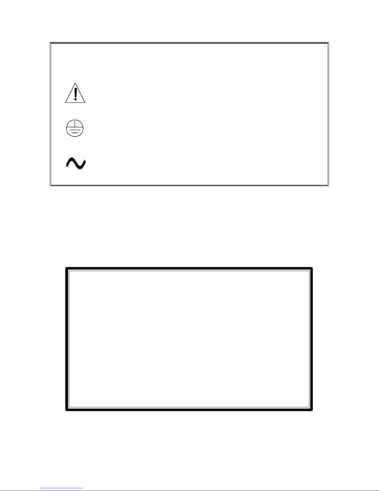
Definition of Equipment Symbols
This symbol means CAUTION and alerts you to possible danger or
instrument malfunction. Refer to this manual before proceeding.
This symbol means that this is a protective ground terminal and
alerts you to connect an earth ground to it.
This symbol means that there is alternating current present and
alerts you to be careful.
WARRANTY
GLI International, Inc. warrants the Model D53 to be free from defects in material
or workmanship for a period of 2 years (24 months) from the date of shipment of
this product from our facility. A warranty claim will not be honored if defects are
not reported within the warranty period, or if GLI International determines that
defects or damages are due to normal wear, misapplication, lack of maintenance, abuse, improper installation, alteration, or abnormal conditions. GLI
International’s obligation under this warranty shall be limited to, at its option, replacement or repair of this product. The product must be returned to GLI
International, freight prepaid, for examination. The product must be thoroughly
cleaned and any process chemicals removed before it will be accepted for replacement or repair. GLI International’s liability shall not exceed the cost of the
product. Under no circumstances will GLI International be liable for any incidental or consequential damages, whether to person or property. GLI International
will not be liable for any other loss, damage or expense of any kind, including
loss of profits, resulting from the installation, use, or inability to use this product.
Model D53 D.O. (universal-mount 1/2 DIN) Rev. 0-599
4
CONDENSED OPERATING INSTRUCTIONS
This manual contains details for all operating aspects of the instrument. The following condensed instructions are provided to assist you in getting the instrument started up and operating as quickly as
possible. These condensed instructions only pertain to basic dissolved oxygen measurement op-
eration (in ppm). To use specific features of the instrument, refer to the appropriate sections in this
manual for instructions.
A. CONNECTING SENSOR(S)
The analyzer can always be used with one sensor connected to SENSOR A terminals. When the
analyzer is equipped with the optional two sensor input software, a second sensor can be connected
to SENSOR B terminals and used for monitoring.
1. After the analyzer is properly mounted (Part Two, Section 2), install the GLI membrane dissolved
oxygen sensor(s). Refer to the sensor instruction manual for details.
2. When using GLI mounting hardware, plug the sensor cable into the mating receptacle on the
junction box. Route the 6-conductor interconnect cable (GLI part number 1W1100) from the
junction box to the analyzer.
3. At the analyzer end of the interconnect cable, twist the two shield wires together. Then insulate
them with plastic tubing or tape to prevent inadvertent shorting, and connect the combined shield
to one of the 5 open holes on the grounding strip at the bottom of the analyzer case (Figure 2-3).
4. Connect the other interconnect cable wires to the analyzer SENSOR A terminals on TB1,
matching colors as indicated:
Sensor A
Interconnect Cable Connections
Wire Colors At Analyzer Terminals Wire Colors At Analyzer Terminals
Red #10 on TB1 Red #16 on TB1
Green #11 on TB1 Green #17 on TB1
Blue #12 on TB1 Blue #18 on TB1
White #13 on TB1 White #19 on TB1
Black #14 on TB1 Black #20 on TB1
Yellow #15 on TB1 Yellow #21 on TB1
Cable shields Grounding strip lug Cable shields Grounding strip lug
Optional Sensor B Input
Interconnect Cable Connections
5. At the junction box end of the interconnect cable, twist the two shield wires together. Then connect the combined shield to the junction box terminal corresponding to the white wire with black
stripe. Connect the other interconnect cable wires to terminals corresponding to their wire colors.
NOTE: When the analyzer is equipped with the optional sensor quick-disconnect receptacle(s),
simply plug the sensor cable(s) into them. This eliminates using the junction box supplied
with GLI sensor mounting hardware, and the need for interconnect cable.
B. CONFIGURING SENSOR TEMPERATURE ELEMENT(S)
The analyzer is supplied factory-set for automatic temperature compensation using the NTC 30K
ohm thermistor element built into GLI membrane dissolved oxygen sensors. For fixed manual temperature compensation, you must change the temperature element type to “MANUAL” (see Part
Three, Section 4.3, subheading “Selecting Temperature Element Type”) and enter a temperature.
NOTE: When the analyzer is equipped with the optional two sensor input software and only one
sensor is being used, the unused sensor input must be set for “MANUAL” compensation to
prevent a “WARNING: CHECK STATUS” message from appearing.
Rev. 0-599 Model D53 D.O. Analyzer (universal-mount 1/2 DIN)
(continued on next page)
5
CONDENSED OPERATING INSTRUCTIONS
C. CONNECTING LINE POWER
Important: Follow the instructions in Part Two, Section 3.5 to connect line power to the analyzer.
D. ADJUSTING DISPLAY CONTRAST
Ambient lighting conditions may make it necessary to adjust display contrast to improve visibility.
With the MEASURE screen displayed, press and hold the ENTER key and simultaneously press the
ññ or òò key until attaining the desired contrast.
E. CALIBRATING THE ANALYZER
The analyzer must be calibrated for dissolved oxygen concentration so that measured values will
correspond to actual process values. Use one of the three different methods available.
Calibration Tip! It is highly recommended to use the “AIR CAL” method with one of the special
calibration bags provided with the GLI membrane D.O. sensor because this:
• Ensures high calibration accuracy by providing a stable atmosphere at the sensor membrane.
• Provides more convenience than using a portable meter to determine the known D.O. value
(even when an optional GLI washer head assembly is attached to sensor for self-cleaning).
• Provides high repeatability because the sensor is in a controlled environment.
CAUTION:
DURING INTIAL STARTUP AND BEFORE CALIBRATION, ALWAYS CONDITION THE
MEMBRANE D.O. SENSOR BY OPERATING IT IN WATER FOR AT LEAST 12 HOURS TO
POLARIZE THE ELECTRODES. FAILURE TO PROPERLY CONDITION THE SENSOR WILL
RESULT IN SIGNIFICANT MEASUREMENT ERROR.
NOTE: When using a second sensor, calibrate SENSOR B in the same way using its respective
menu screens.
Since GLI highly recommends the “AIR CAL” method for calibration, it is described below. (To use
one of the other methods, refer to Part Three, Section 5 for instructions.) With the “AIR CAL”
method, the analyzer automatically calibrates itself using the atmospheric pressure or altitude value
you previously entered, and the measured temperature in the calibration bag. (For theoretical D.O.
calibration values based on measured temperature, refer to Table D. The actual calibration value
may be slightly different because of the variation for the entered atmospheric pressure or altitude.)
1. Enter the known atmospheric pressure or altitude in your geographic area.
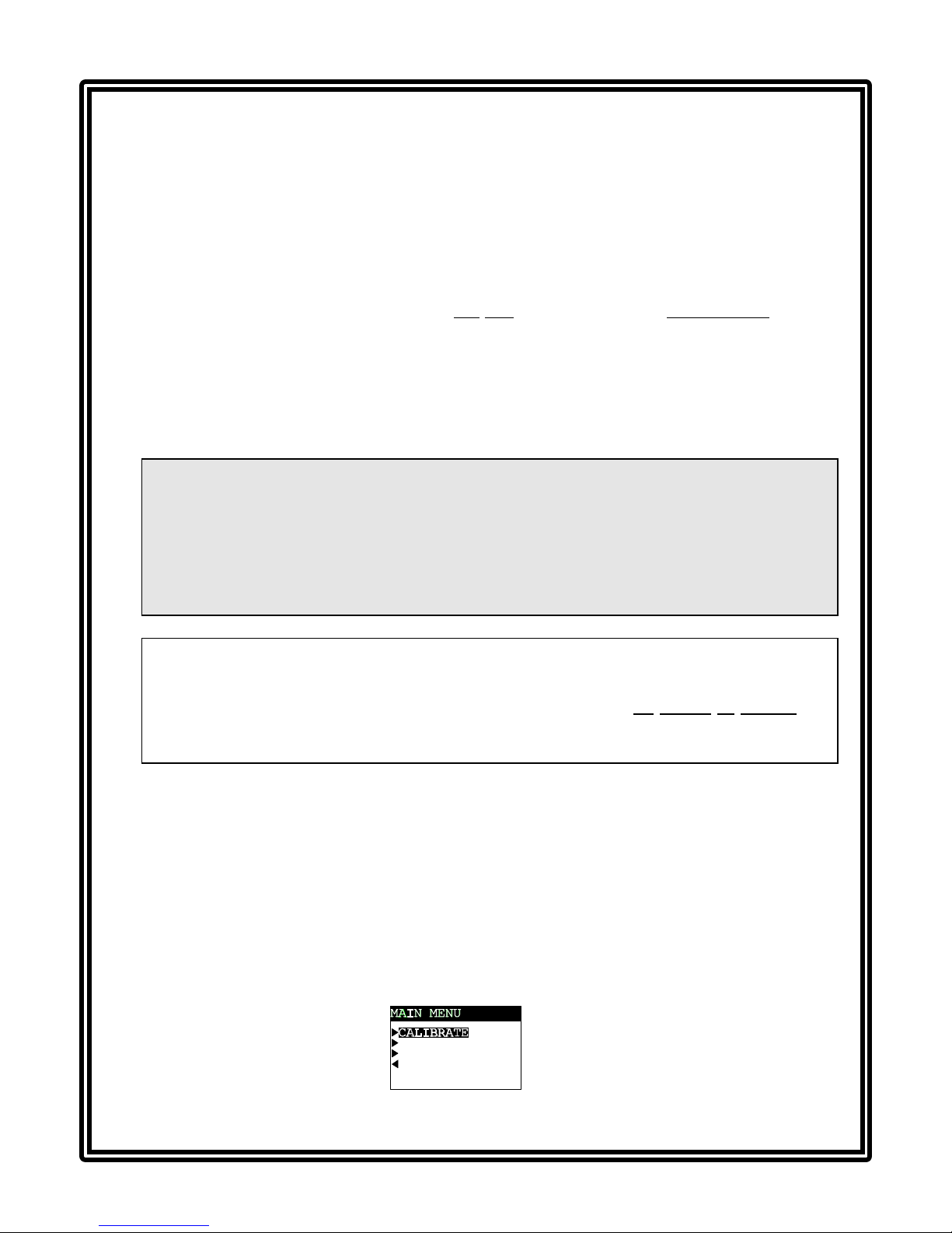
C ON FIG U RE
TES T /MA IN T
EX IT
A. Press MENU key to display
.
Model D53 D.O. (universal-mount 1/2 DIN) Rev. 0-599
(continued on next page)
6

CONDENSED OPERATING INSTRUCTIONS
E. CALIBRATING THE ANALYZER -- (continued)
B. Use òò key to select “CONFIGURE” line, and press ENTER key to display .
C. Use òò key to select “PRESSURE UNITS” line, and press ENTER key to display .
Use òò and ññ keys to select the desired units (pressure in mm of mercury or altitude in feet
or meters), and press ENTER key.
D. With the screen displayed, use òò key to select the “SENSOR” or
“SENSOR A” line and press ENTER key to display:
E. Use òò key to select the “SET PRESSURE” or “SET ALTITUDE” line, and press ENTER key
to display or . Adjust the displayed value to the known
pressure or altitude, and press ENTER key to enter the value. (Use ïï and ðð keys for
coarse adjust; ññ and òò keys for fine adjust.)
Calibration Tip! If at any time during calibration, the “CONFIRM FAILURE?” screen appears,
press ENTER key to confirm. Then, use the ññ or òò key to select between “CAL REPEAT?” or
“CAL EXIT?” and do one of the following:
• With the “CAL REPEAT?” screen selected, press ENTER key to repeat calibration.
• With the “CAL: EXIT?” screen selected, press ENTER key. Then, after the “CONFIRM
ACTIVE?” screen appears, press ENTER key to return the analog outputs and relays to their
active states (MEASURE screen appears).
C ON FIG U RE
TES T /MA IN T
EX IT
2. Press MENU key to display
(continued on next page)
.
Rev. 0-599 Model D53 D.O. Analyzer (universal-mount 1/2 DIN)
7
CONDENSED OPERATING INSTRUCTIONS
E. CALIBRATING THE ANALYZER -- (continued)
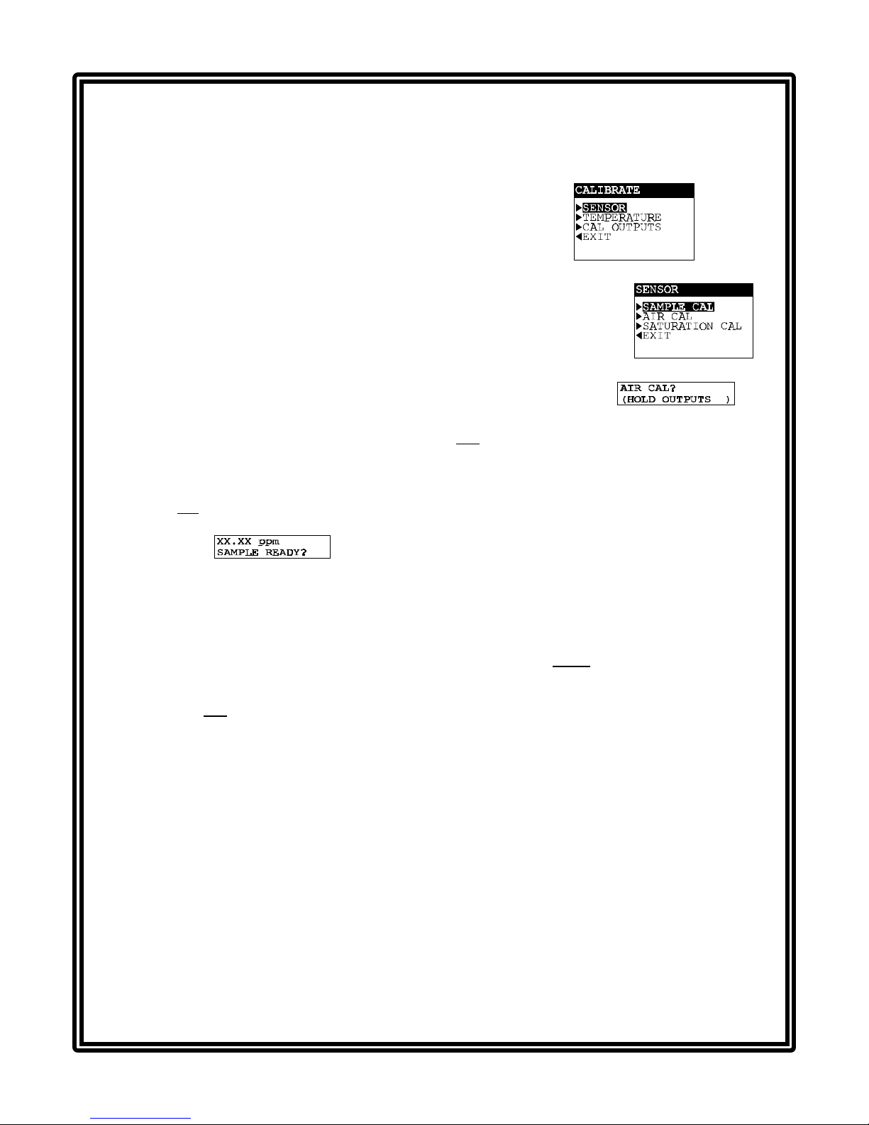
3. With the “CALIBRATE” line selected, press ENTER key to display .
4. With the “SENSOR” or “SENSOR A” line selected, press ENTER key to display .
5. Use òò key to select the “AIR CAL” line, and press ENTER key to display .
6. Press ENTER key to “hold” the analog outputs and relays at their present states during zeroing.
(Outputs can also be transferred to present values or allowed to remain active.)
7. Remove the sensor from the conditioning water, place the provided special calibration bag over
the wet membrane end of the sensor, and secure the bag to the sensor body.
8. With the screen displayed and the sensor held in air, press ENTER key to
start the automatic calibration (“AIR CAL PLEASE WAIT” screen appears for a few minutes enabling the D.O. and temperature signals to stabilize).
9. After the “AIR CAL: CONFIRM CAL OK?” screen appears, press ENTER key to end calibration.
10. After the “CONFIRM ACTIVE?” screen appears showing the active measurement reading, remove the calibration bag from the sensor, and place the sensor into the process. When the
reading corresponds to the actual typical process value, press ENTER key to return the analog
outputs and relays to their active states (MEASURE screen appears).
This completes GLI’s “AIR CAL” calibration. The analyzer is now ready to accurately measure dissolved oxygen concentration in ppm.
To change the display units on the MEASURE screen, for example, from ppm to mg/l or % saturation, refer to Part Three, Section 4.3 under the subheading “Selecting Measurement Display Format.”
F. COMPLETING ANALYZER CONFIGURATION
To further configure the analyzer to your application requirements, use the appropriate CONFIGURE
screens to make selections and “key in” values. Refer to Part Three, Section 4 for complete configuration details.
Model D53 D.O. (universal-mount 1/2 DIN) Rev. 0-599
8
TABLE OF CONTENTS
PART ONE - INTRODUCTION
SECTION 1 GENERAL INFORMATION
1.1 Capability Highlights........................................................15-17
1.2 Modular Construction............................................................17
1.3 Retained Configuration Values............................................. 17
1.4 Analyzer Serial Number........................................................ 17
1.5 EMI/RFI Immunity .................................................................18
SECTION 2 SPECIFICATIONS ...................................................................19-20
PART TWO - INSTALLATION
SECTION 1 UNPACKING.................................................................................21
SECTION 2 MECHANICAL REQUIREMENTS
2.1 Location ................................................................................21
2.2 Mounting..........................................................................21-23
2.3 Conduit Hole Requirements..................................................23
SECTION 3 ELECTRICAL CONNECTIONS
3.1 GLI Membrane Dissolved Oxygen Sensor(s)...................24-26
3.2 Analog Outputs.....................................................................27
3.3 Relay Outputs.......................................................................28
3.4 Closed Contact TTL Input.....................................................29
3.5 Line Power.......................................................................29-30
PART THREE - OPERATION
SECTION 1 USER INTERFACE
1.1 Display.............................................................................31-32
1.2 Keypad.............................................................................32-33
1.3 MEASURE Screen (normal display mode)............................ 34
SECTION 2 MENU STRUCTURE
2.1 Displaying Main Branch Selection Screen............................35
2.2 Displaying Top-level Menu Screens ................................35-36
2.3 Displaying Submenu Screens...............................................36
2.4 Adjusting Edit/Selection Screen Values................................ 36
2.5 Entering (Storing) Edit/Selection Screen Values/Choices ....36
SECTION 3 ADJUSTING DISPLAY CONTRAST............................................ 37
Rev. 0-599 Model D53 D.O. Analyzer (universal-mount 1/2 DIN)
9

TABLE OF CONTENTS (continued)
SECTION 4 CONFIGURING THE ANALYZER
4.1 Selecting Language to Operate Analyzer............................. 37
4.2 Configuring Units for Application Conditions:
Selecting Atmospheric Pressure Units
(mmHg, altitude in ft., or altitude in m).......................38
Selecting Salinity Units (mS/cm or milliMol/l) ..................38
4.3 Configuring Sensor (A and B) Characteristics:
Selecting Measurement Display Format
(ppm, mg/l, % saturation)........................................... 39
Setting Sensor Signal Filter Time.................................... 40
Setting Atmospheric Pressure Value............................... 40
Setting Salinity Value (for process or clean water).......... 41
Selecting Pulse Suppression (on/off)..............................41
Changing Top Line Notation on MEASURE Screen........... 42
Selecting Temperature Element Type........................42-43
4.4 Selecting Temperature Display Format (°C or °F)................43
4.5 Configuring Outputs (1 and 2):
Assigning Representative Parameter.........................44-45
Setting Parameter Values for 0/4 and 20 mA.............45-46
Setting Transfer Value (mA)............................................46
Setting Output Filter Time ............................................... 47
Setting Output Scale Low Endpoint (0/4 mA).................. 47
4.6 Configuring Relays (A, B, C, and D):
Assigning Representative Parameter.........................48-49
Selecting Function Mode (alarm, control,
status, or timer).....................................................49-50
Selecting Transfer Mode (relay on or off)........................ 51
Setting Activation (Configuration) Values...................51-53
4.7 Enabling/Disabling Passcode ..........................................53-54
4.8 Summary of Configuration Settings
(Ranges/Choices and Defaults).......................................55-57
SECTION 5 CALIBRATING THE ANALYZER
5.1 Things to Know About D.O. Calibration................................58
5.2 D.O. Calibration:
5.3 Temperature Calibration:
5.4 Analog Outputs (1 and 2) Calibration ..............................70-71
Model D53 D.O. (universal-mount 1/2 DIN) Rev. 0-599
SAMPLE CAL Method ................................................60-62
AIR CAL Method (highly recommended)....................62-64
SATURATION CAL Method........................................64-65
1 POINT SAMPLE Method .........................................66-67
2 POINT SAMPLE Method .........................................67-69
10

TABLE OF CONTENTS (continued)
SECTION 6 TEST/MAINTENANCE
6.1 Checking Analyzer, Sensor, and Relay Status...............72-73
6.2 Holding Outputs...................................................................74
6.3 Resetting Overfeed Timers.................................................. 74
6.4 Providing Output (1 and 2) Test Signals ............................. 75
6.5 Testing Relay (A, B, C, and D) Operation ...........................75
6.6 Checking EPROM Version ..................................................76
6.7 Selecting Type of Simulated Value...................................... 76
6.8 Setting Simulation Value .....................................................77
6.9 Resetting Configuration Values to Factory Defaults.......77-78
6.10 Resetting Calibration Values to Factory Defaults................ 78
SECTION 7 RELAY OVERFEED TIMER FEATURE
7.1 Why Use an Overfeed Timer...............................................79
7.2 Configuring Relay Overfeed Timers.................................... 79
7.3 Overfeed Timer “Timeout” Operation .................................. 79
7.4 Resetting Overfeed Timers.................................................. 79
7.5 Interactions with Other Analyzer Functions....................79-80
SECTION 8 HART OPTION
8.1 Introduction .......................................................................... 81
8.2 Analyzer Operating Modes for HART Network...............82-83
8.3 SINGLE MODE (Point-to-Point) Wiring Arrangement ......... 83
8.4 MULTI-DROP Wiring Arrangement.....................................84
8.5 HART Preferences Setup:
Changing Polling Address..............................................85
Viewing Number of Required Preambles ..................85-86
8.6 Device Preferences Setup:
Viewing Final Assembly Number.................................... 86
Viewing Model Number.............................................86-87
Viewing Manufacturer.....................................................87
Assigning a Tag .............................................................87
Assigning a Descriptor................................................... 88
Assigning a Message..................................................... 88
Assigning User-defined Date ....................................88-89
Viewing Identification (ID) ..............................................89
Viewing Revisions..........................................................89
8.7 “Master Reset” Function......................................................90
8.8 “Refresh” Function...............................................................90
8.9 Protocol Command Set for PC Programming......................90
Rev. 0-599 Model D53 D.O. Analyzer (universal-mount 1/2 DIN)
11
TABLE OF CONTENTS (continued)
PART FOUR - SERVICE AND MAINTENANCE
SECTION 1 GENERAL INFORMATION
1.1 Inspecting Sensor Cable(s) ..................................................91
1.2 Replacing Fuse(s).................................................................91
1.3 Replacing Relays..................................................................91
SECTION 2 PRESERVING MEASUREMENT ACCURACY
2.1 Keeping Sensor(s) Clean...................................................... 92
2.2 Keeping Analyzer Calibrated ................................................92
2.3 Avoiding Electrical Interference............................................92
SECTION 3 TROUBLESHOOTING
3.1 Ground Loops:
Determining if Ground Loop Exists.................................. 93
Finding Source of Ground Loop......................................94
3.2 Isolating Measuring System Problem:
Checking Electrical Connections..................................... 94
Verifying Sensor Operation.............................................94
Verifying Analyzer Operation......................................94-95
Verifying Interconnect Cable Integrity .............................95
SECTION 4 ANALYZER REPAIR/RETURN
4.1 Customer Assistance............................................................96
4.2 Repair/Return Policy.............................................................96
PART FIVE - SPARE PARTS AND ACCESSORIES
......................................................................................................97
Model D53 D.O. (universal-mount 1/2 DIN) Rev. 0-599
12

TABLE OF CONTENTS (continued)
ILLUSTRATIONS
Figure 1-1 EMI/RFI Immunity Diagram ........................................................................................18
Figure 2-1 Analyzer Mounting Arrangements..............................................................................22
Figure 2-2 Analyzer Installation Dimension Details .....................................................................23
Figure 2-3 Analyzer Terminal Block Designations.......................................................................25
Figure 2-4 Connecting GLI Membrane Dissolved Oxygen Sensor(s)..........................................26
Figure 2-5 Connecting Control/Alarm Device(s) to Electromechanical Relay(s)..........................28
Figure 2-6 Connecting 115 Volt Single Phase Line Power (90-130 VAC)...................................30
Figure 2-7 Connecting 230 Volt Single Phase Line Power (180-260 VAC).................................30
Figure 2-8 Connecting 230 Volt Split Phase Line Power (180-260 VAC)....................................30
Figure 3-1 Analyzer Keypad........................................................................................................32
Figure 3-2 Location of Analyzer SINGLE MODE/MULTI-DROP Switch.......................................83
Figure 3-3 HART SINGLE MODE (Point-to-Point) Wiring Arrangement (for single analyzer)......83
Figure 3-4 HART MULTI-DROP Wiring Arrangement (for multiple analyzers).............................84
TABLES
Table A Relay Configuration Settings.................................................................................51-52
Table B Analyzer Configuration Settings (Ranges/Choices and Defaults).........................55-57
Table C Comparison of Calibration Methods...........................................................................59
Table D Temperature versus Water-saturated Concentration of Oxygen................................62
Table E Relay Overfeed Timer Interactions with Other Analyzer Functions............................80
Rev. 0-599 Model D53 D.O. Analyzer (universal-mount 1/2 DIN)
13

Model D53 D.O. (universal-mount 1/2 DIN) Rev. 0-599
14
PART ONE - INTRODUCTION SECTION 1 - GENERAL INFORMATION
PART ONE - INTRODUCTION
SECTION 1
GENERAL INFORMATION
1.1 Capability Highlights
Sensor Input
The analyzer always has one sensor input but may be
equipped with the optional two sensor input software. This
option provides two independent sensor inputs for monitoring two measurement points. Each input accepts a GLI
membrane dissolved oxygen sensor that has a built-in NTC
30K ohm thermistor.
MEASURE Screen
(normal display mode)
Passcode-protected
Access
The measured dissolved oxygen is shown on the
MEASURE screen (normal display mode). When the analyzer is equipped with the optional two sensor input
software, pressing the ðð or ïï key while viewing the
MEASURE screen sequentially shows these measurements:
• Measured Sensor A dissolved oxygen.
• Measured Sensor B dissolved oxygen.
• Measured Sensor A and B dissolved oxygen and
temperatures (all together on same screen).
The bottom auxiliary display line, shown in reverse video,
can be changed by pressing the òò and ññ keys to show
these other measurements:
• Measured Sensor A temperature (°C or °F).
• Measured Sensor B temperature (°C or °F).
• Analog Output #1 value (mA).
• Analog Output #2 value (mA).
For security, you can enable a passcode feature to restrict
access to configuration and calibration settings to authorized personnel only. See Part Three, Section 4.7 for details.
Calibration Guidelines
Rev. 0-599 Model D53 D.O. Analyzer (universal-mount 1/2 DIN)
Three methods are provided for D.O. calibration. It is highly
recommended to use the “AIR CAL” method for convenience and accuracy. For calibration details on all methods,
refer to Part Three, Sections 5.1 and 5.2. The analyzer also
provides two methods for calibrating temperature (Section
5.3). This feature, however, is typically not needed since the
analyzer is factory-calibrated for highly accurate tempera-
15

PART ONE - INTRODUCTION SECTION 1 - GENERAL INFORMATION
ture measurement. The mA
values for each analog output
can also be calibrated (Section 5.4).
Analog Outputs
☞
Model D53 D.O. (universal-mount 1/2 DIN) Rev. 0-599
Relays
☞
16

PART ONE - INTRODUCTION SECTION 1 - GENERAL INFORMATION
The analyzer provides two
isolated analog outputs (#1
and #2). Each output can be
set to be 0-20 mA or 4-20
mA, and assigned to represent the measured dissolved
oxygen or temperature.
The analyzer has four electromechanical relays, all with
SPDT contacts. Each relay can be set to function as a control relay, dual-alarm relay, status relay, or a timer relay,
and assigned to be driven by the measured dissolved oxygen or temperature.
NOTE: When the analyzer
is equipped with the
optional two sensor
input software, an
analog output can
NOTE: When the analyzer is equipped with the optional
two sensor input software, a relay can also represent the SENSOR B measured dissolved oxygen
or temperature.
also represent the
SENSOR B measured dissolved
oxygen or tem-
Since timer and status function relays are driven by
other criteria, the parameter assigned to these re-
lays is not relevant and, therefore, disregarded.
perature.
Refer to Part Three, Section 4.6 for relay setup details.
Parameter values can be
entered to define the endpoints at which the minimum
and maximum analog output
values are desired.
During calibration, both analog outputs can be selected
to:
• Hold their present values
(HOLD OUTPUTS)
• Transfer to preset values
to operate control elements by an amount
corresponding to those
values (XFER
OUTPUTS)
• Remain active to respond
to the measured value
(ACTIVE OUTPUTS).
For analog output transfer
setup details, see Part Three,
Section 4.5 under the subheading “Setting Transfer
Value.”
Rev. 0-599 Model D53 D.O. Analyzer (universal-mount 1/2 DIN)
17

PART ONE - INTRODUCTION SECTION 1 - GENERAL INFORMATION
☞
1.2 Modular Construction
NOTE: When a relay is set to function as a status relay, it is
no longer configurable. Instead, it becomes a dedicated system diagnostic-only alarm relay that
automatically energizes when the “WARNING
CHECK STATUS” message flashes on the
MEASURE screen. This occurs when the analyzer
detects a “fail” diagnostic condition. See Part Three,
Section 6.1 for more details.
Except for status relays, during calibration the relay on/off
states are affected in the same way as the analog outputs
by the “(HOLD/XFER/ACTIVE OUTPUTS)” screen selection. These relays are also held at their present on/off
states, transferred to desired preset on/off states, or remain
active to respond to measured values. For relay transfer
setup details, see Part Three, Section 4.6, under the subheading “Selecting Transfer Mode.”
The modular construction of the analyzer simplifies field
servicing and provides electrical safety. The front door/
keypad assembly uses voltages no greater than 24 VDC,
and is completely safe to handle.
1.3 Retained
Configuration Values
1.4 Analyzer
Serial Number
Opening the analyzer door accesses terminals inside the
enclosure for electrical connections. Line power must be
connected to specifically designated terminals on TB3.
WARNING:
REMOVE LINE POWER BEFORE NEARING THIS AREA
TO AVOID ELECTRICAL SHOCK.
All user-entered configuration values are retained indefinitely, even if power is lost or turned off. The non-volatile
analyzer memory does not require battery backup.
A label with the analyzer model number, serial number,
build date, and other items is affixed to the top of the enclosure.
Model D53 D.O. (universal-mount 1/2 DIN) Rev. 0-599
18
PART ONE - INTRODUCTION SECTION 1 - GENERAL INFORMATION
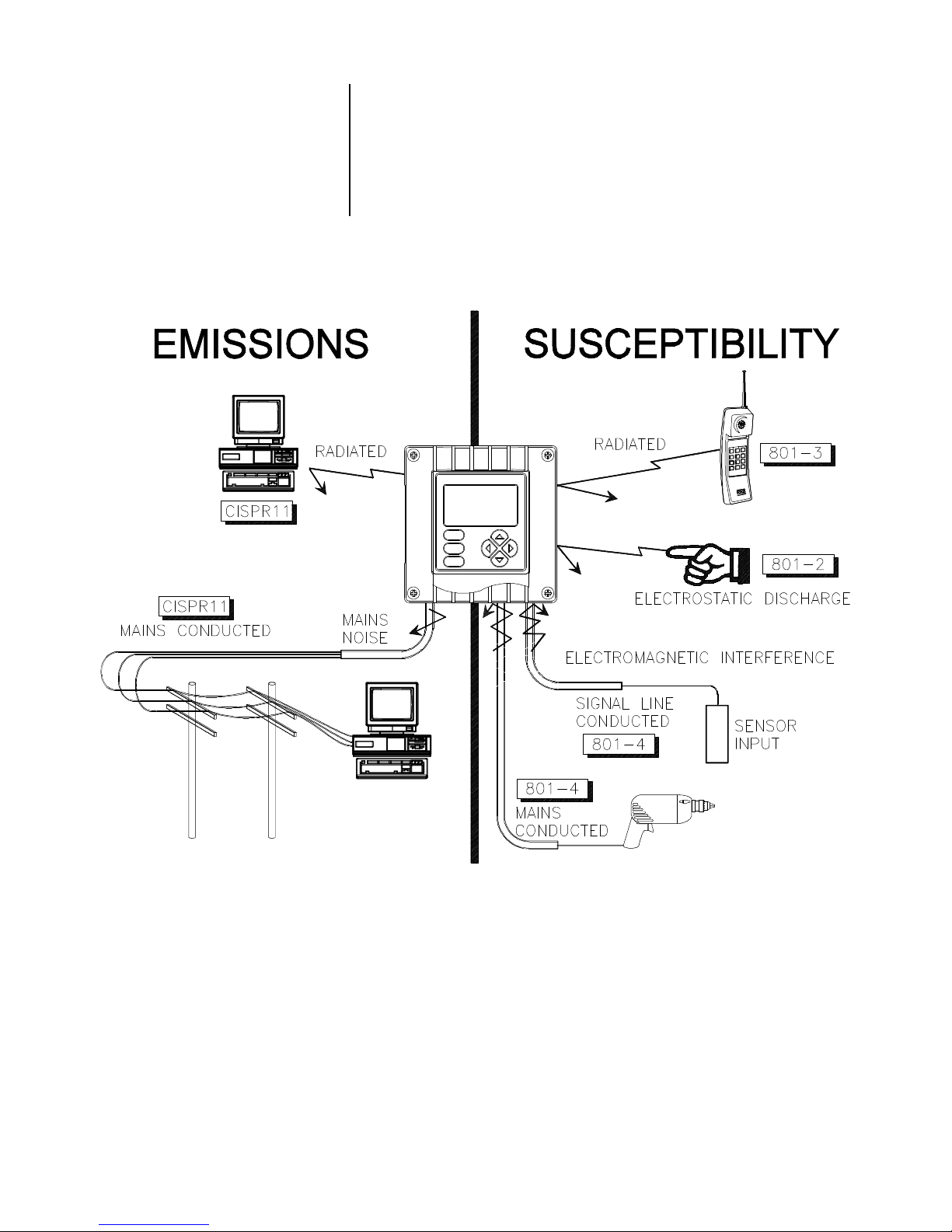
1.5 EMI/RFI Immunity
The analyzer is designed to provide protection from most
normally encountered electromagnetic interference. This
protection exceeds US standards and meets European
IEC 801-series testing for electromagnetic and radio frequency emissions and susceptibility. Refer to Figure 1-1
and the specifications in Section 2.1 for more information.
Rev. 0-599 Model D53 D.O. Analyzer (universal-mount 1/2 DIN)
FIGURE 1-1 EMI/RFI Immunity Diagram
19

PART ONE - INTRODUCTION SECTION 2 - SPECIFICATIONS
SECTION 2
SPECIFICATIONS
2.1 Operational
Display....................................... Graphic dot matrix LCD, 128 x 64 pixels with
LED backlighting; 1/2 inch (13 mm) main
character height; 1/8 inch (3 mm) auxiliary
information character height; menu screens
contain up to six text lines
Measurement Ranges
Dissolved Oxygen................. 0-99.99 ppm, 0-99.99 mg/l, or 0-999.9 % sat.
Temperature......................... 32.0-212.0°F or 0.0-100.0°C
mA Outputs (#1 and #2)........ 0.00-20.00 mA or 4.00-20.00 mA
Ambient Conditions:
Operation.............................. -4 to +140°F (-20 to +60°C); 0-95% relative
humidity, non-condensing
Storage................................. -22 to +158°F (-30 to +70°C); 0-95% relative
humidity, non-condensing
Relays: Types/Outputs.................Four electromechanical relays; SPDT (Form C)
contacts; U.L. rated 5A 115/230 VAC, 5A @ 30
VDC resistive
Operational Mode............Each relay (A, B, C, and D) can be assigned to
be driven by:
• Sensor A dissolved oxygen
• Sensor A temperature
• Sensor B dissolved oxygen
• Sensor B temperature
Function Modes:
Control.................... Settings for high/low phasing, setpoint, dead-
band, overfeed timer, off delay, and on delay
Alarm.........................Settings for low alarm point, low alarm point
deadband, high alarm point, high alarm point
deadband, off delay, and on delay
Status.........................Not configurable; relay only activates when a
sensor or analyzer “fail” diagnostic WARNING
condition exists
Timer..........................Relay is activated by user-entered interval and
time duration values to control a sensor cleaning
system such as a GLI air blast cleaning system
Indicators.........................Relay A, B, C, and D annunciators indicate
respective relay status
only with optional
two sensor input
}
software
Model D53 D.O. (universal-mount 1/2 DIN) Rev. 0-599
Temperature Compensation....... Automatic from 32.0 to 122.0°F (0.0-50.0°C),
or manually fixed at a user-entered temperature
Sensor-to-Analyzer Distance...... 1000 ft. (305 m) maximum
Power Requirements.................. 90-130 VAC, 50/60 Hz. (10 VA max.) or
180-260 VAC, 50/60 Hz. (10 VA max.)
D.O. Calibration Methods:
SAMPLE CAL......................... Enter one sample value derived by laboratory
analysis or a comparison reading.
AIR CAL................................. For use only when the sensor is calibrated in
air. The analyzer computes and displays the
ppm value based on the entered atmospheric
pressure or altitude, and the temperature of
the 100% saturated air.
20

PART ONE - INTRODUCTION SECTION 2 - SPECIFICATIONS
SATURATION CAL................. For use only when the process or clean water is
known to be 100% saturated with air. The ana-
lyzer computes and displays the ppm value
based on the entered atmospheric pressure or
altitude, and the temperature and salinity of the
100% saturated process or clean water.
Analog Outputs (two)................. Isolated 0/4-20 mA; each with 0.004 mA (12-
bit) resolution and capability to drive up to
600 ohm loads
NOTE: Each output can be assigned to represent Sensor A measurement
or temperature or, when equipped with the optional two sensor input
software, the Sensor B measurement or temperature. Parameter
values can be entered to define the endpoints at which the minimum
and maximum mA output values are desired. During calibration, both
outputs can be selected to hold their present values, transfer to preset values to operate control elements by an amount corresponding
to those values, or remain active to respond to the measured value.
Communication: RS-232........... Enables configuration and retrieval of measured
data for one analyzer using IBM-compatible PC
and optional GLI software tool kit
HART ............. Enables configuration and retrieval of measured
data for up to 15 analyzers over communication
link using appropriate hand-held terminal or data
system with HART software
2.2 Analyzer Performance
(Electrical, Analog Outputs)
2.3 Mechanical
Memory Backup (non-volatile).... All user settings are retained indefinitely in
memory (EEPROM)
EMI/RFI Conformance................ Exceeds US and meets European standards
for conducted and radiated emissions and
immunity; certified CE compliant for applications as specified by EN 50081-1 for
emissions and EN 50082-2 for immunity
Electrical Certifications:
General Purpose (pending)..... UL, C-UL, FM, and CENELEC
Division 2 (pending) ................ UL, C-UL, and FM: Groups A, B, C, D, F, and G
Zone 2 (pending).................... CENELEC: Group IIC
Accuracy.................................... ± 0.1% of span
Sensitivity.................................. ± 0.05% of span
Repeatability.............................. ± 0.05% of span
Temperature Drift ....................... Zero and Span: ± 0.02% of span per °C
Response Time.......................... 1-60 seconds to 90% of value upon step
change
Enclosure................................... NEMA 4X; polycarbonate face panel, epoxy-
coated cast aluminum door and case with four
1/2 inch (13 mm) conduit holes; nylon mounting bracket, and stainless steel hardware
Rev. 0-599 Model D53 D.O. Analyzer (universal-mount 1/2 DIN)
Mounting Configurations ............ Panel, surface, and pipe (horizontal and
vertical) mounting
Net Weight................................. 3.5 lbs. (1.6 kg) approximately
21

PART TWO - INSTALLATION SECTION 1 - UNPACKING
PART TWO - INSTALLATION
SECTION 1
UNPACKING
After unpacking, it is recommended to save the shipping
carton and packing materials in case the instrument must be
stored or re-shipped. Inspect the equipment and packing
materials for signs of shipping damage. If there is any evidence of damage, notify the transit carrier immediately.
SECTION 2
MECHANICAL REQUIREMENTS
2.1 Location
2.2 Mounting
1. It is recommended to locate the analyzer as close as
possible to the installed sensor. The maximum allowable
distance between an installed sensor and the analyzer is
1000 feet (305 m).
2. Mount the analyzer in a location that is:
➥ Clean and dry where there is little or no vibration.
➥ Protected from corrosive fluids.
➥ Within ambient temperature limits (-4 to +140°F or
-20 to +60°C).
CAUTION:
EXPOSING THE ANALYZER TO DIRECT
SUNLIGHT MAY INCREASE THE OPERATING
TEMPERATURE ABOVE ITS SPECIFIED LIMIT.
Figure 2-1 illustrates the various ways to mount the analyzer using the supplied bracket and hardware. Determine
the mounting method and attach the hardware as shown in
the respective illustration. Refer to Figure 2-2 for analyzer
installation dimension details.
Model D53 D.O. (universal-mount 1/2 DIN) Rev. 0-599
22

PART TWO - INSTALLATION SECTION 2 - MECHANICAL REQUIREMENTS
FIGURE 2-1 Analyzer Mounting Arrangements
Rev. 0-599 Model D53 D.O. Analyzer (universal-mount 1/2 DIN)
23
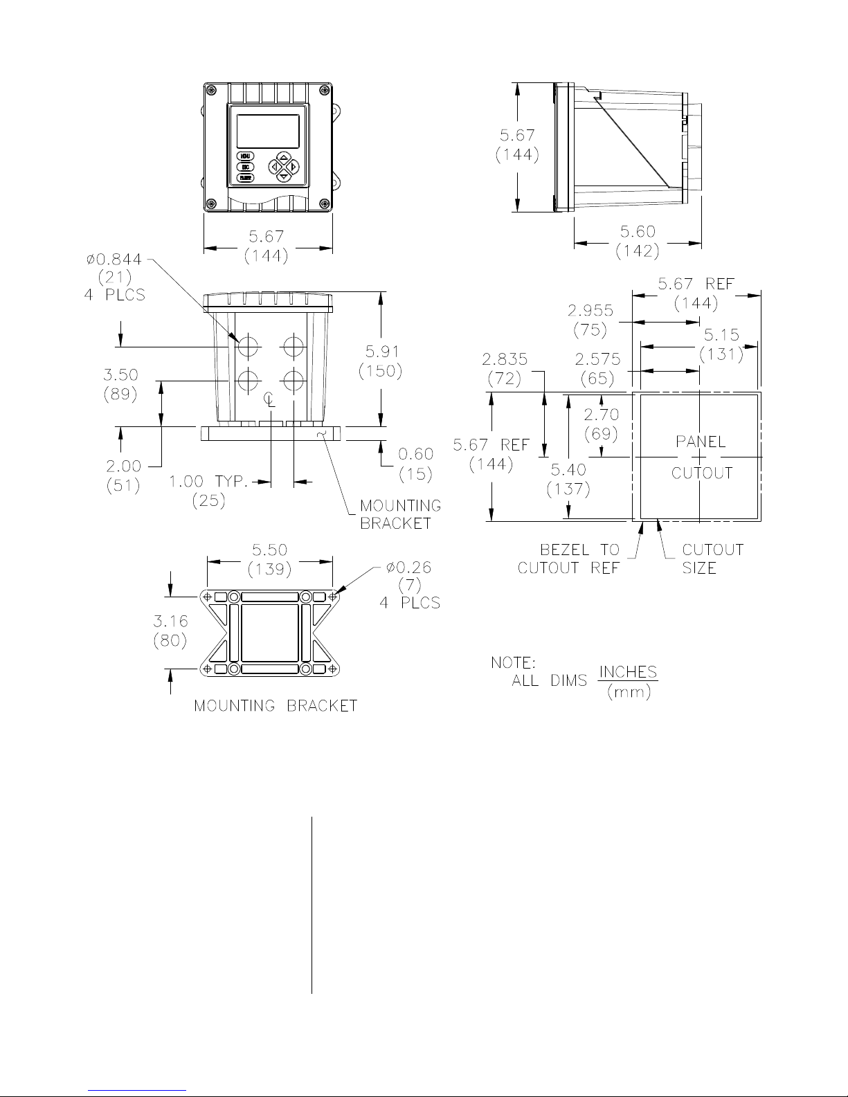
PART TWO - INSTALLATION SECTION 2 - MECHANICAL REQUIREMENTS
FIGURE 2-2 Analyzer Installation Dimensions Details
2.3 Conduit Hole
Requirements
☞
Model D53 D.O. (universal-mount 1/2 DIN) Rev. 0-599
Recommendation: Run all wiring to the analyzer in 1/2inch, grounded metal conduits. If using only shielded cables, appropriate strain reliefs or cable grips are required.
(GLI offers accessory cable grips, part number 3H1091, and
watertight locknuts, part number 3H1230, for cable entries.)
Seal unused cable entry holes with appropriate plugs.
NOTE: Use NEMA 4-rated fittings and plugs to maintain the
watertight integrity of the NEMA 4X enclosure.
24
PART TWO - INSTALLATION SECTION 3 - ELECTRICAL CONNECTIONS
SECTION 3
ELECTRICAL CONNECTIONS
To access terminal blocks for electrical connections, open
the left-hinged enclosure door by unscrewing the four fasteners. Figure 2-3 shows the terminal block arrangement
and terminal designations inside the analyzer.
NOTE: All terminals are suitable for single wires up to 14
☞
☞
Wiring Tip! To comply with European Community (CE)
electromagnetic compatibility requirements, follow these
general wiring guidelines:
1. Keep all cable shields as short as possible inside the
AWG (2.5 mm2).
analyzer, and connect them to the ground terminals
provided. Performance may be improved by using
cable glands that enable the shield to directly contact
the analyzer chassis.
3.1 GLI Membrane
Dissolved Oxygen
Sensor(s)
☞
☞
2. Use Steward ferrite 28 B0590-000 or equivalent on
the sensor cable -- two turns required.
3. In harsh conducted RF conditions, connect the earth
ground of the analyzer to a local, known earth ground
source.
NOTE: For ease of wiring, connect line power and relay
outputs through the back conduit holes before connecting the sensor, and analog outputs.
The analyzer can always be used with one sensor connected to SENSOR A terminals. When the analyzer is
equipped with the optional two sensor input software, a
second sensor can be connected to SENSOR B terminals
and used for monitoring.
Wiring Tip! Route the sensor cable (and interconnect
cable, if used) in 1/2-inch, grounded metal conduit to
protect it from moisture, electrical noise, and mechanical
damage.
☞
Rev. 0-599 Model D53 D.O. Analyzer (universal-mount 1/2 DIN)
NOTE: Do not route the sensor and interconnect cables in
any conduit containing AC power wiring (“electrical
noise” may interfere with the sensor signal).
25
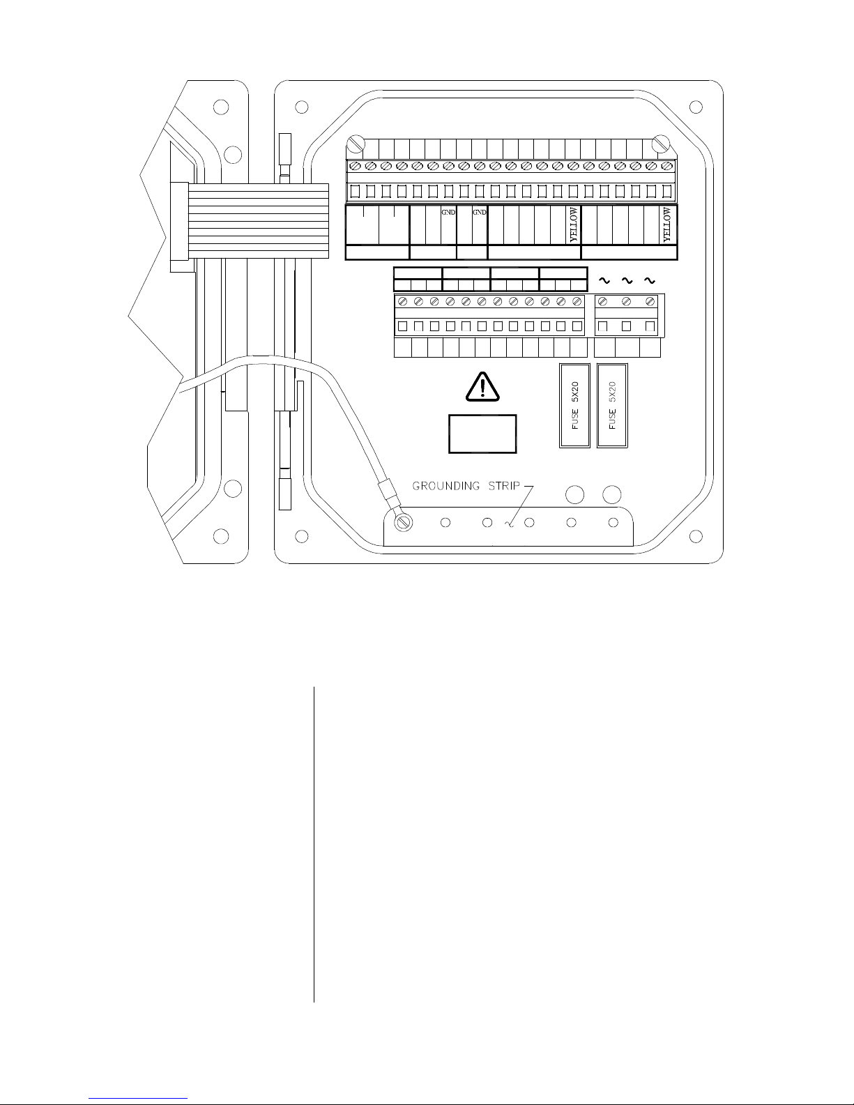
PART TWO - INSTALLATION SECTION 3 - ELECTRICAL CONNECTIONS
DISSOLVED OXYGEN ANALYZER
11
1
+-+
HART
OUT 1
4-20 mA
-
OUT 2
RELAY A
NC
TX RX
RS-232 TTL
RELAY B
NOCOM NC NOCOM NC
107 85 63 42 9
+
RED
BLUE
WHITE
GREEN
SENSOR A
RELAY C
COM
BLACK
RELAY D
COMNO NC NO
RED
GREEN
SENSOR B
230
18 191614 1512 13 17
BLUE
115 N
WHITE
BLACK
2120
TB1
TB2
1
6 74 52 33
POWER
90-130 VAC
180-260 VAC
10VA 50/60 Hz
F
T T
FIGURE 2-3 Analyzer Terminal Block Designations
All GLI membrane dissolved oxygen sensors have a built-in
NTC 30K ohm thermistor for automatic temperature compensation.
TB3
411 1298 10
1
100mA80mA
23
F
2
Model D53 D.O. (universal-mount 1/2 DIN) Rev. 0-599
Use these steps to connect each sensor and refer to Figure
2-4 for analyzer interconnect cable connection details.
1. Install the GLI membrane D.O. sensor(s) using GLI (or
other appropriate) mounting hardware. Refer to the sensor instruction manual for details.
2. When using GLI mounting hardware, plug the sensor
cable into the mating receptacle on the junction box.
Route the 6-conductor interconnect cable (GLI part
number 1W1100) from the junction box to the analyzer.
26
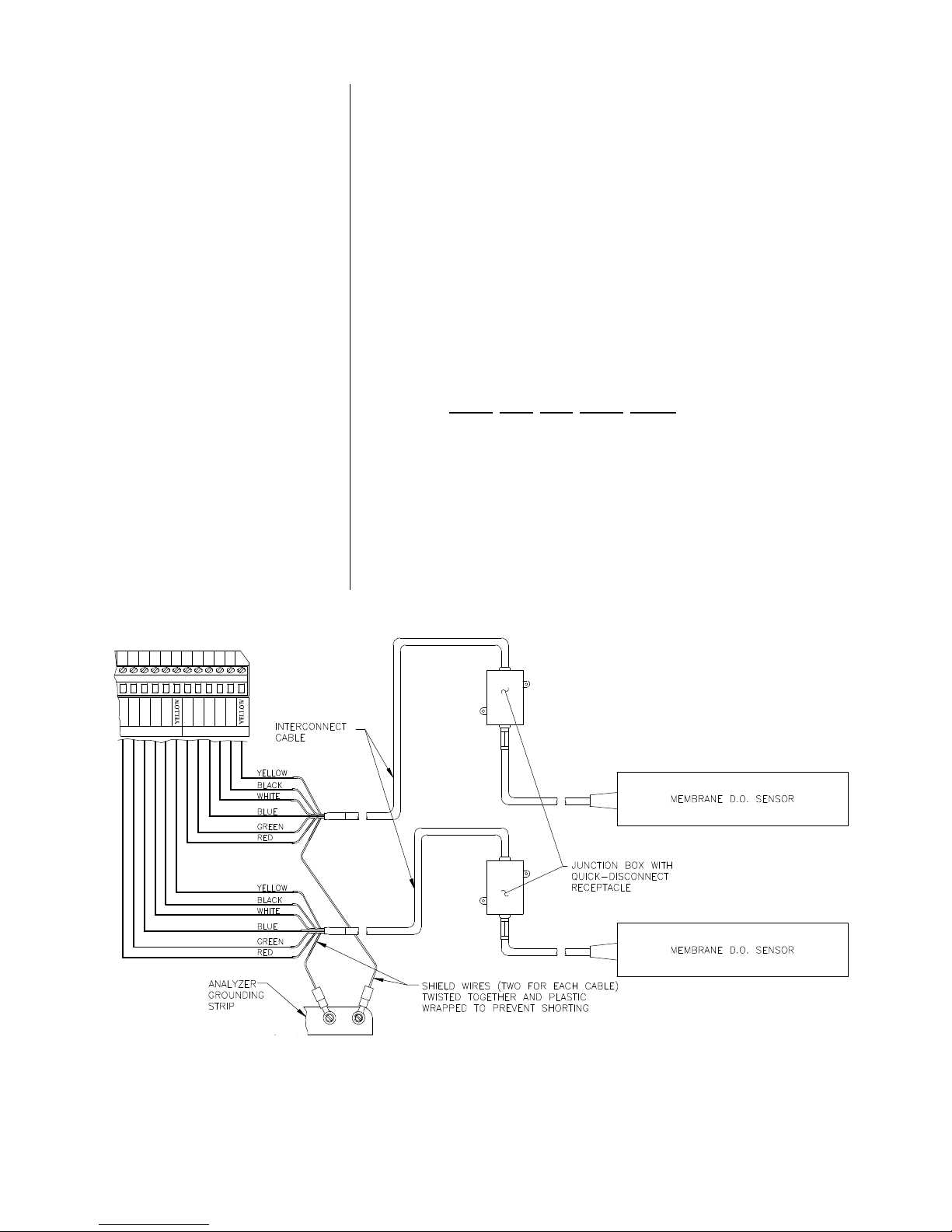
PART TWO - INSTALLATION SECTION 3 - ELECTRICAL CONNECTIONS
3. At the analyzer end of the interconnect cable, twist the
two shield wires together. Then insulate them with plastic tubing or tape to prevent inadvertent shorting, and
connect the combined shield to one of the 5 open holes
on the grounding strip at the bottom of the analyzer
case.
4. Connect the other interconnect cable wires to the analyzer SENSOR A and, if used, SENSOR B terminals on
TB1, matching colors as indicated.
5. At the junction box end of the interconnect cable, twist
the two shield wires together. Then connect the combined shield to the junction box terminal corresponding
to the white wire with black stripe. Connect the other interconnect cable wires to terminals corresponding to
their wire colors.
☞
sensor quick-disconnect receptacle(s), simply plug
the sensor cable(s) into them. This eliminates using
the junction box supplied with GLI sensor mounting
hardware, and the need for interconnect cable.
11
NOTE: When the analyzer is equipped with the optional
10
TB1
RED
BLUE
WHITE
GREEN
SENSOR A
BLACK
RED
SENSOR B
18 191614 1512 13 17
GREEN
BLUE
WHITE
2120
BLACK
FIGURE 2-4 Connecting GLI Membrane Dissolved Oxygen Sensor(s)
Rev. 0-599 Model D53 D.O. Analyzer (universal-mount 1/2 DIN)
27
PART TWO - INSTALLATION SECTION 3 - ELECTRICAL CONNECTIONS
3.2 Analog Outputs
☞
☞
Two isolated analog outputs (#1 and #2) are provided. Each
output can be set to be 0-20 mA or 4-20 mA. Also, each
output can be assigned to represent the measured dissolved oxygen or temperature.
NOTE: When the analyzer is equipped with the optional
two sensor input software, an analog output can
also represent the SENSOR B measured dissolved oxygen or temperature.
For details on configuring the outputs, refer to Part Three,
Section 4.5.
Wiring Tip! Use high quality, shielded instrumentation
cable for connecting the analog outputs. To protect the
output signal from EMI/RFI, connect cable shields to one
of the 5 open holes on the grounding strip at the bottom
of the case (Figure 2-3).
Each 0/4-20 mA output can drive a load of up to 600 ohms.
☞
• For Output #1: Connect the load to Terminals 1 and 2 on
TB1, matching polarity as indicated.
• For Output #2: Connect the load to Terminals 3 and 4 on
TB1, matching polarity as indicated.
NOTE: When using the HART communication option, a
digital signal is encoded onto the 4-20 mA analog
Output #1 signal. In a HART point-to-point wiring
configuration, Output #1 remains available for normal use. However, in a HART multi-drop wiring
configuration, Output #1 becomes dedicated to that
function and cannot be used. See Part Three, Section 8 for more HART communication information.
Model D53 D.O. (universal-mount 1/2 DIN) Rev. 0-599
28
PART TWO - INSTALLATION SECTION 3 - ELECTRICAL CONNECTIONS
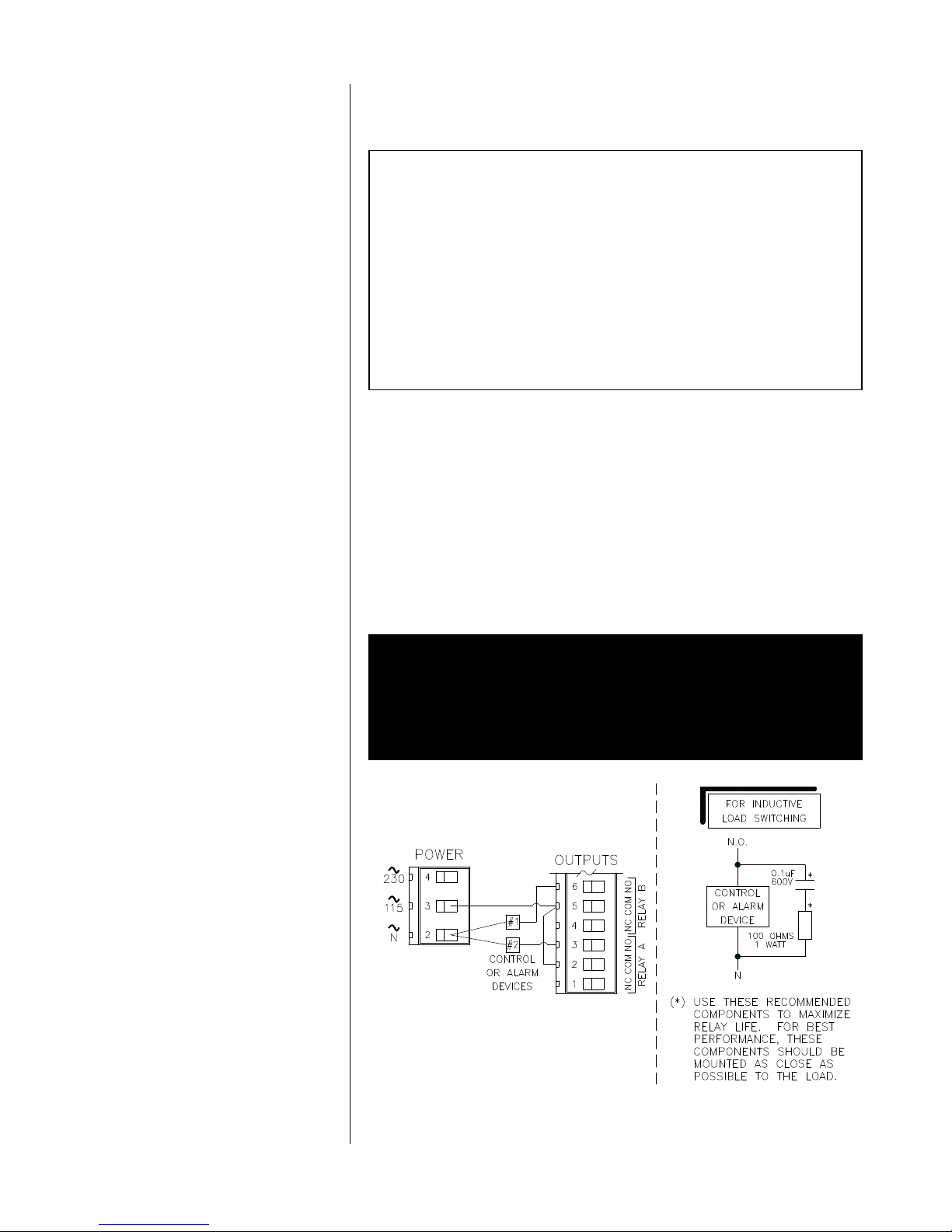
3.3 Relay Outputs
The analyzer is equipped with four electromechanical relays. For relay setup details, see Part Three, Section 4.6.
CAUTION:
DO NOT EXCEED THE CONTACT RATING FOR
EACH RELAY (5A 115/230 VAC). WHEN SWITCHING
LARGER CURRENTS, USE AN AUXILIARY RELAY
SWITCHED BY THE ANALYZER RELAY TO EXTEND
ANALYZER RELAY LIFE. WHEN USING RELAY
OUTPUTS, MAKE SURE THAT LINE POWER WIRING
CAN ADEQUATELY CONDUCT THE CURRENT
DRAW OF THE SWITCHED LOAD(S).
Four sets of SPDT relay outputs (Relays A, B, C, and D) are
provided at Terminals 1 through 12 on TB2. The relay out-
puts are not powered. The line power used to power the
analyzer may also be used to power control/alarm devices
or GLI air blast sensor cleaning systems with these relay
contacts. Refer to Figure 2-5 for a general wiring arrangement. Always check control wiring to insure that line power
will not be shorted by the relay switching action, and that
wiring conforms to local codes.
WARNING:
MAKE SURE THAT LINE POWER IS NOT PRESENT
WHILE CONNECTING WIRES TO TB2 RELAY
TERMINALS.
Rev. 0-599 Model D53 D.O. Analyzer (universal-mount 1/2 DIN)
FIGURE 2-5 Connecting Control/Alarm Device(s) To
Electromechanical Relay(s)
29

PART TWO - INSTALLATION SECTION 3 - ELECTRICAL CONNECTIONS
3.4 Closed Contact
TTL Input
3.5 Line Power
☞
The analyzer closed contact TTL input feature enables you
to conveniently:
• Hold analog outputs at their present values.
• Hold control and alarm relays in their present on/off
states.
• Suspend countdown, temporarily, of active timer relays.
To initiate these actions, simply locally or remotely jumper
TTL Terminals 8 and 9 on TB1.
NOTE: During a calibration, the selected output state
(“HOLD,” “XFER” or “ACTIVE”) overrides the actions of the TTL input feature.
Refer to Figures 2-6, 2-7 or 2-8 on the next page and connect line power to TB3 terminals using the standard threewire connection arrangement. Use wiring practices which
conform to local codes (example: National Electric Code
Handbook in the U.S.A.).
☞
☞
WARNING:
REMOVE LINE POWER WHILE CONNECTING LINE
POWER WIRES TO THE TB3 TERMINALS. ALSO,
USE ONLY THE STANDARD THREE-WIRE CONNECTION ARRANGEMENT FOR SINGLE-PHASE LINE
POWER TO PREVENT AN UNSAFE CONDITION, AND
TO ENSURE PROPER ANALYZER OPERATION.
NOTE: In all cases, connect the line power cable ground
wire (usually green) to one of the 5 open holes on
the grounding strip at the bottom of the analyzer
case.
The “115” and “230” voltage circuits are protected with internal, board-mounted slow-blow fuses.
NOTE: For 230 volt split phase line power, be sure to con-
form to local codes with regard to fusing the 115
volt line connected to the “N” terminal.
Model D53 D.O. (universal-mount 1/2 DIN) Rev. 0-599
30
 Loading...