

GlideTrak Indoor Trainer User Manual
GlideTrak Assembly & Set Up
1
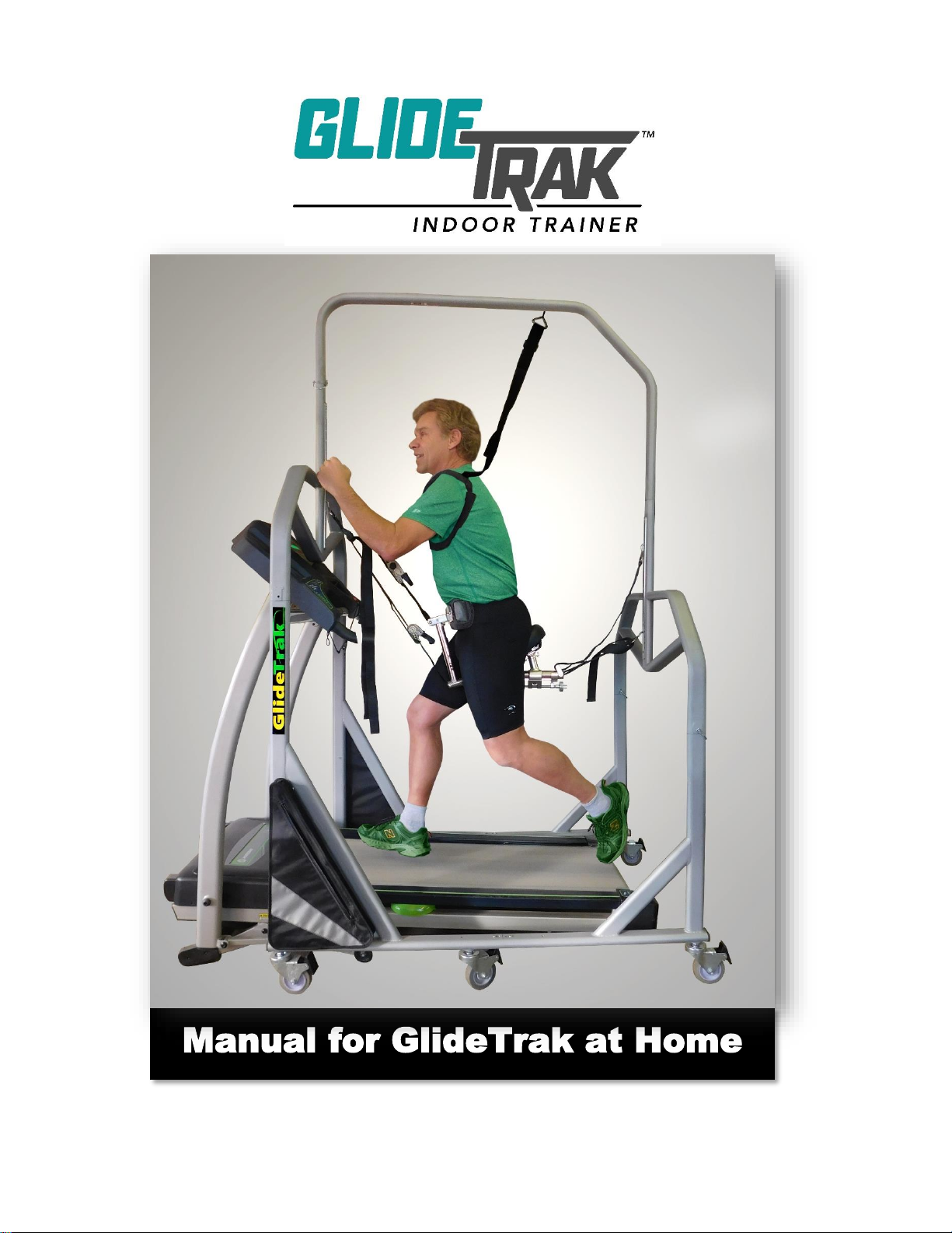
Manual for GlideTrak at Home

GlideTrak Assembly & Set Up
2

GlideTrak Assembly & Set Up
3
TABLE OF CONTENTS
GlideTrak Assembly Instructions……………………………………………. Pg. 4
Wheels …………………………………………………………………………. Pg. 5
Frame ……………………………………………………………….……… Pg.5 – 8
Seat Assembly …………………………………………………………… Pg. 9-10
Seat Assembly Placement …………………………………………….……. Pg. 11
Seat Set-Up Instructions ………………………………………………… Pg. 12-15
Unweighting the body …………………………………………………….… Pg. 16
Using the Ratchets ……………………………………………….…………. Pg. 18
Seat Assembly Adjustment …………………………………………………. Pg. 19
Evaluate “unweighting” position ……………………………………………. Pg. 20
Dismounting the GlideTrak …………………………………………………. Pg. 21
Reset Ratchets after workout ………………………………………………. Pg. 22
GlideTrak Assembly Tool List, Parts Identification ………………….... Pg. 23-26
GlideTrak Assembly & Set Up
4
3. For assembly: each part of the GlideTrak frame has several stickers with a letter. There is a
sticker with a letter placed on the end of every part of the GlideTrak.
GlideTrak™
Assembly Instructions
1. The GlideTrak should be
assembled in the room where you
will use your treadmill and
GlideTrak. Remove all GlideTrak
parts from the box and lay them
out onto your floor space. Remove
all packaging materials from each
part to prepare for assembly.
2. Refer to the Parts Identification
Pages (pgs. 23-26) to identify
each part. The photographs also
indicate the side of the part that
should face upwards to make
assembly as easy as possible.
Lay the parts on the floor as
shown in the Parts Identification
Guide (pgs. 23-26).
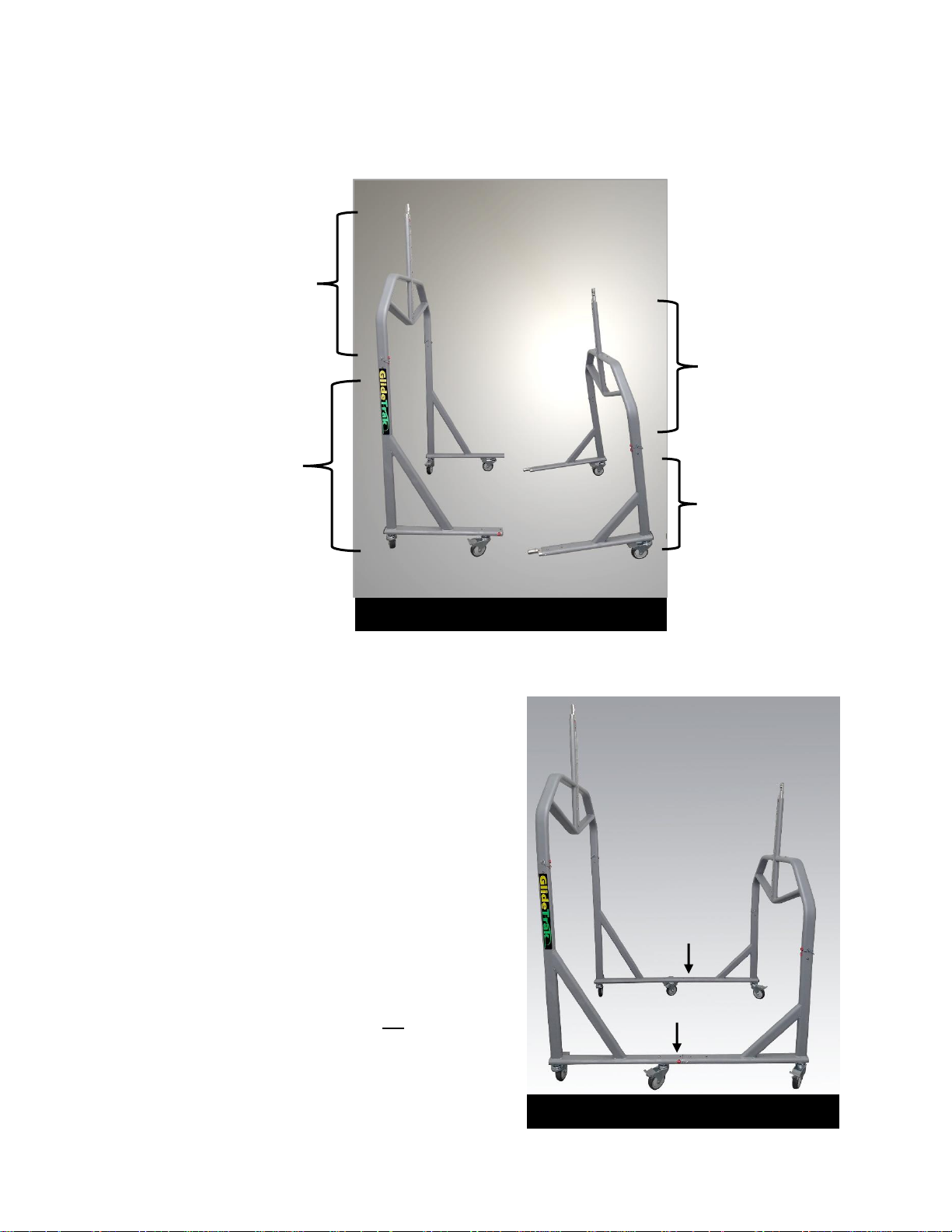
FRONT Mid-Section:
(Photo 1). with letter I at top edge
and the letters A and B at the
bottom edges.
Photo 1 Front Mid-Section
I
A
B
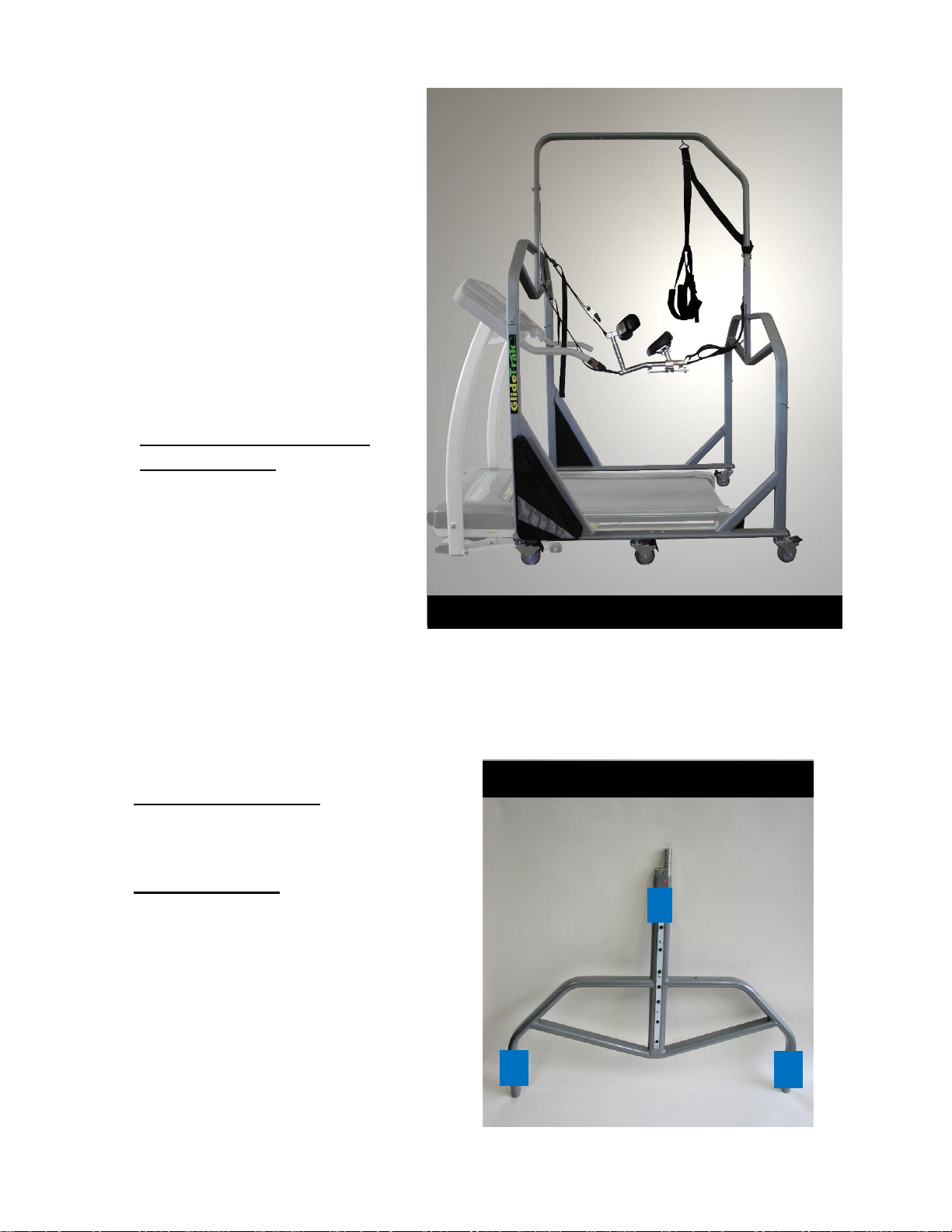
GlideTrak Fully Assembled
GlideTrak Assembly & Set Up
5
4. Assembly starts with the Wheels.
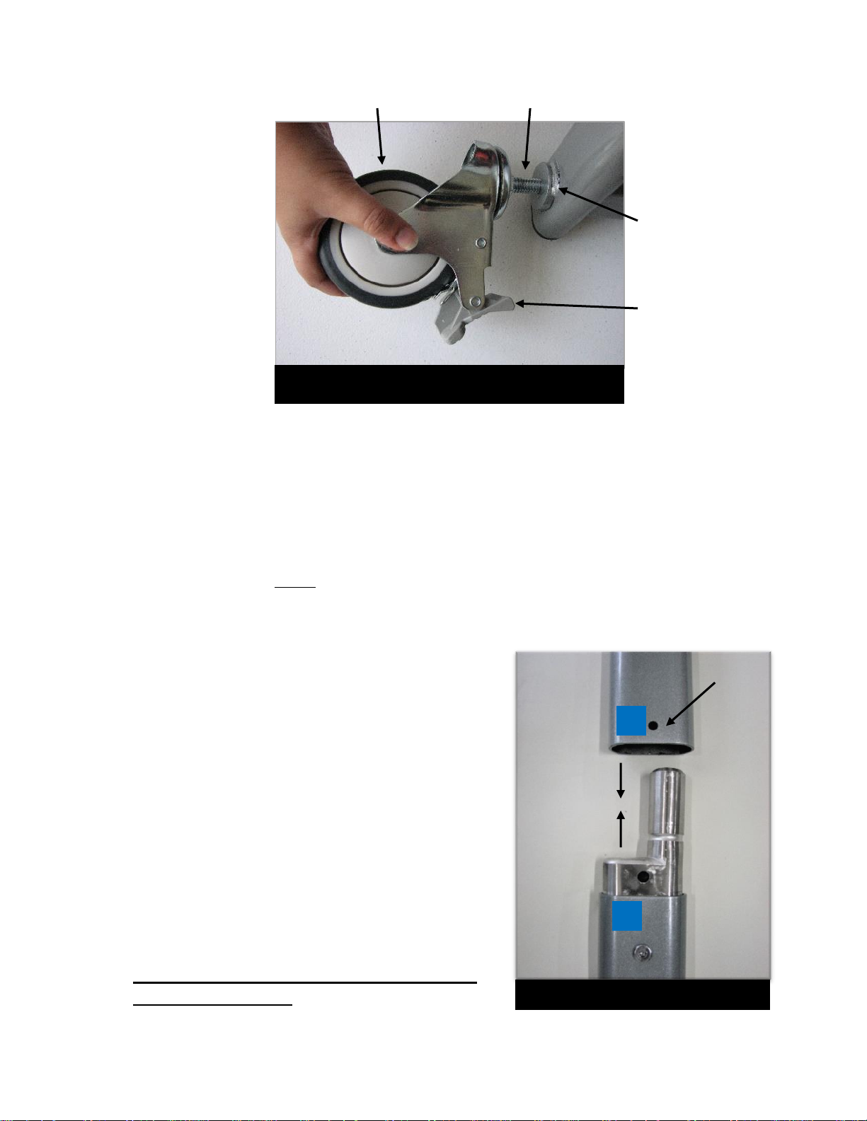
The 6 Wheels have Locking Levers. Lock the Wheels by pressing down the Locking Levers on
each Wheel. ( Photo 2)
5. The 4 Base Legs have 6 threaded, Wheel Base-Plates. As illustrated in Photo 2, screw the
threaded post of each locked Wheel into the Base-Plate.
6. Locate the bag of hardware. The hardware includes 9-barrel bolts and 2 Allen wrenches.
(Parts Identification Guide pgs. 23-26)
Wheel
Wheel Post
Wheel Base Plate
Locking Lever
Sticker
with
letter A
Sticker
with
letter A
Bolt
Hole
Photo 3 Front Mid-Section
7. As noted, each part of the GlideTrak frame has several
stickers, with a letter placed on each end of the part.
Assembly will follow the ALPHABET IN ORDER.
8. Locate the Front Mid-Section part with the sticker
with letter A on one end.
9. Connect this section to the end of the Long Base Leg
with the matching sticker A. (Photo 3 & 4)
Lettered Stickers on parts must line up when frame
pieces are put together. (Photo 3)
Photo 2 Wheel
A
A
GlideTrak Assembly & Set Up
6
Sticker
with
letter C
Sticker
with
letter C
C
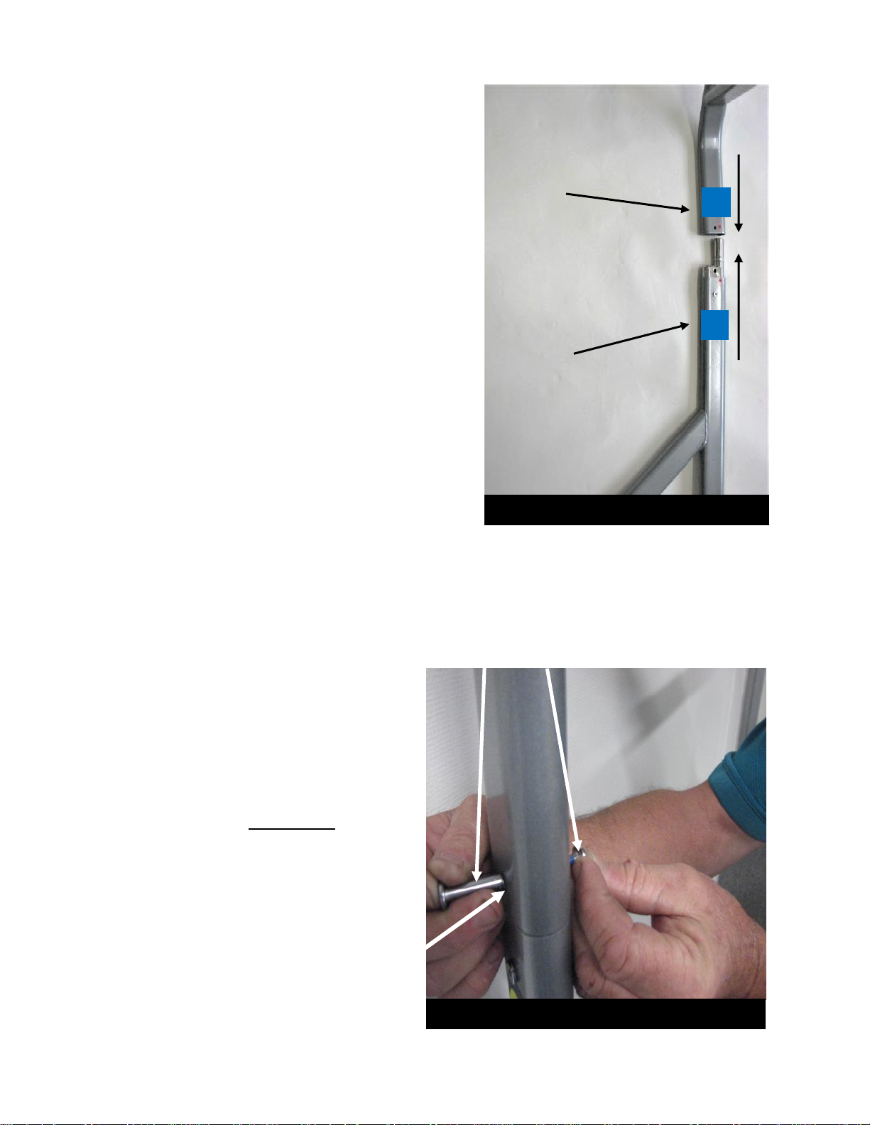
10. Follow the alphabet, matching the
stickers at the ends of the parts labeled
B to B, C to C, and D to D.
Only attach up to D for now.
(Photo 3 & 5)
Photo 4 Join parts labled A through D
C
C
Bolt Hole
Photo 5 Barrel Bolt placed in Bolt Hole
11. When joining the frame, align the Bolt
Holes and attach the Barrel Bolts in
the Bolt Holes. (Photo 3 & 5)
Use an Allen wrench in each hand to
tighten each Bolt. (not shown)
Barrel Bolts
GlideTrak Assembly & Set Up
7
12. Once sections A through D are joined, you will have two sections of the GlideTrak frame as shown in
Photo 6.
13. Slide the two sections together,
aligning stickers E to E and F to F.
The Frame Base will be assembled as
shown in Photo 7 Frame Base. It may
help to unlock the brakes on one
section before sliding the two sections
together. Once in place, re-lock the
brakes.
14. Once the frame is together, place and
tighten Barrel Bolts at E and F.
(Note: If basket pins were ordered, do not
use pins to connect base parts EE, FF or
GG. Only use Barrel Bolts to connect
base leg parts EE, FF, and GG)
Photo 7 Frame Base
F
E
Photo 6 Frame Sections
Rear Mid-Section
with letters C and D
at bottom edges and
letter H at top edge
Short Base Leg with
letters C or D at top
edge, and letters E
or F at bottom
edges
Front Mid-Section with
letters A and B at
bottom edges and letter
I at top edge
Long Base Leg with
letters A or B at top
edges, and letters E
or F at bottom edges
I
D
C
H
ABE
F
F
E
GlideTrak Assembly & Set Up
8
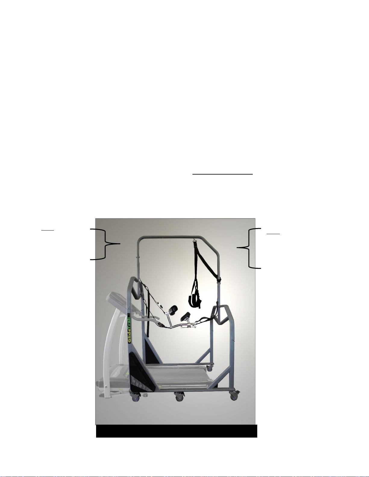
15. The Top Bar of the GlideTrak has 2 parts, a Curved Top Bar (for the front) and an Angled Top
Bar for the rear portion of the bar. (Photo 8 below, and Parts Identification Guide Photo 8 and
Photo 9, pg. 25). Join the two parts of the Top Bar joining the ends marked G and G. Secure the
Top Bar with a Barrel Bolt. (Photo 5 and 8).
16. The ends of the Top Bar will join the Front and Back Mid-section posts. Attach the ends of the
Curved (front) Top Bar by joining I to I, and attach the Angled Top Bar in the rear by joining
H to H. (Photos 6 and 8) Align and insert Barrel Bolts into the Top Bar as shown previously in
Photo 5.
17. Tighten all in the frame with Allen wrenches to complete your frame assembly. (Photo 8).
18. Move the GlideTrak frame and center it over your treadmill. (If you wish, you may unlock the
wheels to move the frame; however, make sure that Wheels are re-locked after the GlideTrak is
in place).
Front: Curved Top
Bar with center
edge marked G
and front end
marked with the
letter I
Rear: Angled Top
Bar with center
edge marked G and
the back edge
marked with the
letter H
G
I
H
Photo 8 Top Bar joined with Front & Mid-Section
GlideTrak Assembly & Set Up
9
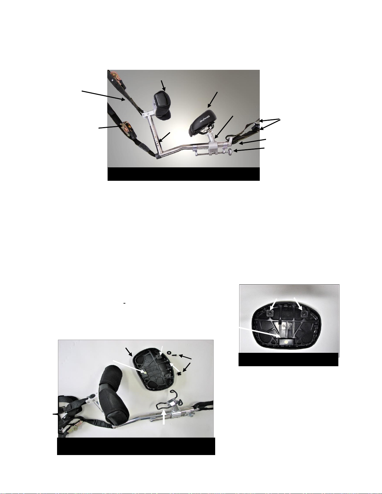
Now you are ready to assemble the Seat Assembly.
19. SEAT ASSEMBLY: Cut away any wrapping and plastic ties from the Seat Assembly. The
Seat Assembly Includes the Back Straps, Seat Post, Adjustment Rod, Hip Post, Hip Pad and
Front Straps. (Photo 8)
When you take it out of the box, the assembly will be in 2 parts. One piece is the bulk of
the Seat Assembly. The second piece is the Seat Pad with attached Seat Screws. To
complete the Seat Assembly, you only need to reattach the Seat Pad. You will need one
Phillips-head screwdriver for this task.
20. To reattach the Seat: Remove the 2 screws
and 2 washers from the back of the Seat Pad.
21, Insert the front of the Wire
Loop of the Seat
Assembly into the Wire
Slot on the back of the
Seat Pad.
(Photos 10 & 11)
Photo 9 Seat Assembly
Seat Pad
Hip Pad faces up
& front
Front Top Strap
Ratchet on
Front Bottom
Strap
Hip Post
Seat Post
Rear Straps
Seat Rail
Adjustment Rod
Photo 10 Seat Pad back view
2 Seat Screws & washers
Wire
Slot of
Seat
Pad
Photo 11 Seat Assembly Frame & detached Seat
Pad with screws and washers
Seat Pad
Seat Screw Hole
Seat
Screws
Wire Loop on Seat
Assembly
Wire Slot on
back of Seat Pad
Seat Screw
Hole
 Loading...