

Page 1
1
TENSION SPRING
INSTALLATION
EXS – 70
www.samsondoors.co.uk
0800 328 6250
www.samsondoors.co.uk
www.samsondoors.co.uk
0800 328 6250
www.samsondoors.co.uk
Page 2

2
Contents
1. Symbols 3
2. General warnings 3
2.1 Safety requirements for assembly and first use 3
3. Terms and conditions 3
4. Area of application
5. Guidelines 4
6. Fixing material building 4
7. System summary 4
7.1 Pre-assembled rail set 5
7.2 Springmatrix EXS70 6
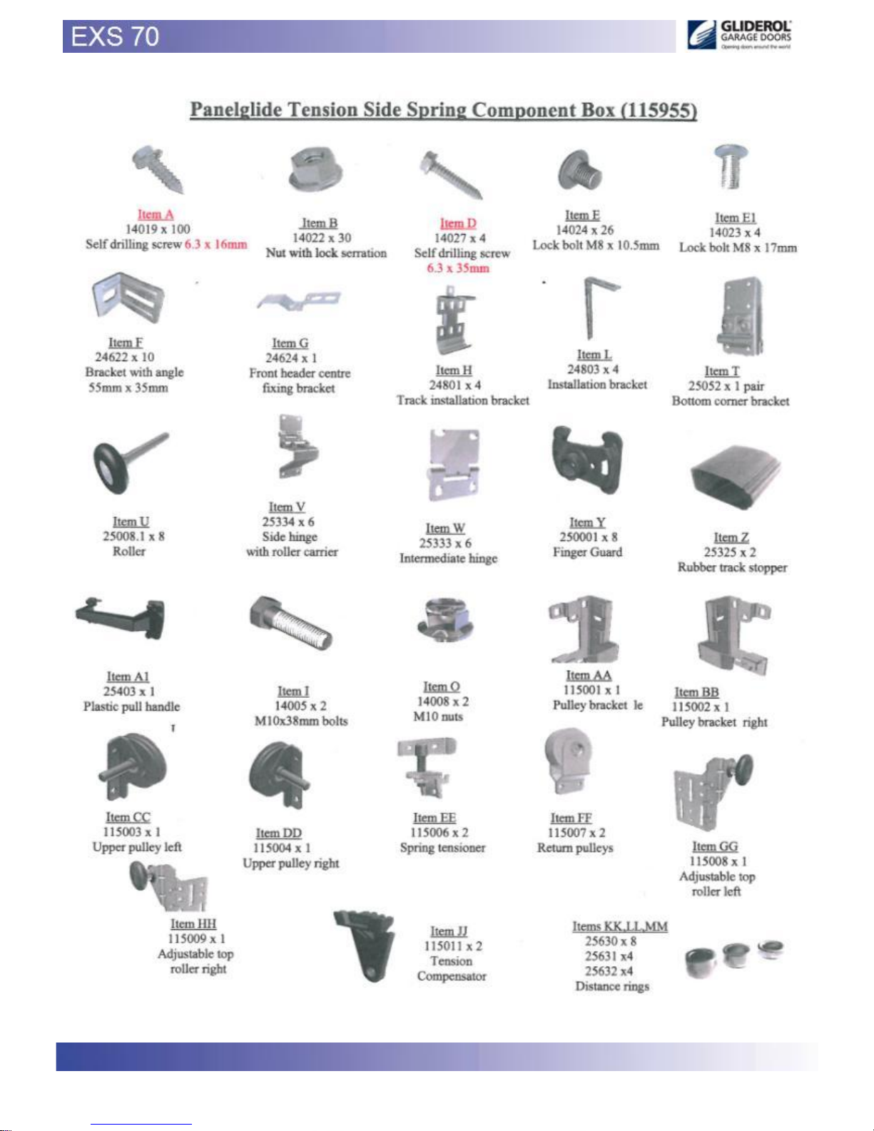
7.3 Standard hardware box 7
8. Fasteners/ tools 8
9. Assembly 9-36
10. Handover 37
10.1 First use 37
11. Electric operator (optional) 37
11.1 To adjust the operator 37
12. Disassembly 38
12.1 Disposal 38
13. Maintenance 38
www.samsondoors.co.uk
0800 328 6250
www.samsondoors.co.uk
www.samsondoors.co.uk
0800 328 6250
www.samsondoors.co.uk
Page 3

3
1. Symbols
Danger
Attention
Additional manuals
2. General warnings
This manual has been prepared for use by qualified personnel and therefore not by trainees or “do it yourselfers”
In case of doubt about the assembly and/or maintenance, please contact DOCO International
To avoid severe personal injury, carefully read and observe all indications and warnings in this manual.
- This manual describes the assembly, use and maintenance of your residential system /door EXS70; this may be
supplemented by other
manuals, for instance the panel assembly manual and operator manual (if applicable.)
- This residential system has been designed in accordance with the latest European standards; however you
have to check yourself
whether this standard corresponds with the local national standard.
- All measurements are in millimeters unless otherwise specified.
- After installation ensure that the CE marking label has been completed and attached.
- Keep this manual in a safe place.
- Subject to technical changes, without written notice.
2 .1 Safety requirements for assembly and first use.
- This residential system may only be mounted, connected and put into operation by qualified personnel.
- Make sure that the power is switched off and remains switched off while electrical work is carried out!
- Never bridge safety devices !
- Adding or leaving out parts can affect the door operation in a negative way and therefore the safety of the
installed sectional door. This
is therefore strongly discouraged!
- Some parts can contain sharp edges: use protective gloves.
- All references to the door/component handing within this manual is always as viewed from inside looking out.
- Never use the sectional door in case or visual damage on the safety devices.
- When performing assembly/maintenance, always wear at least gloves and safety boots and during
drilling/cutting wear safety goggles!
- Make sure that you can always perform your work in a stable environment.
- Secure the assembly/maintenance site with safety ribbon to keep others (children!) at a distance.
- Maintenance must only be performed by a qualified company and/or qualified personnel.
- Make sure there is enough light.
- Only use appropriate tools.
3. Terms and conditions
Our general conditions of delivery and payments are applicable on all our offers, agreements or subsequent
revisions.
A copy of our terms and conditions are available on request or can be downloaded from our website: www.docointernational.com.
4. Area of application
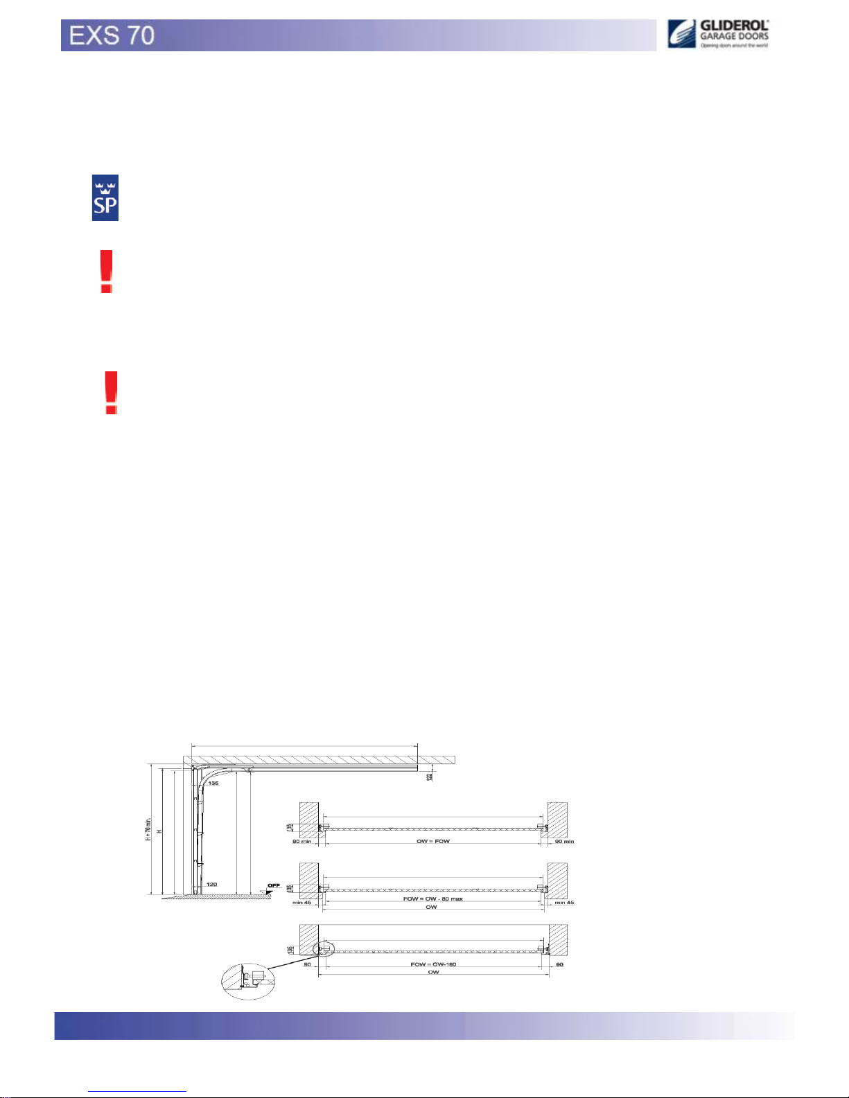
This hardware set has been developed for installation in garages in the private sector
- Maximum width 3000 mm
- Maximum height 2500 mm
- Weight door leaf maximum 100 kg
- Maximum temperature range outside* : -20 degr until + 50 degr C
- Relative humidity 20 – 90%
- Lifetime : 15.000 cycles.
* big differences in temperature between the inside and outside can cause deflection in the panel leafs (bi-metal
effect). In particular dark
coloured panels are susceptible to this problem and should be avoided. Care should be taken during manual
handling as there is a big risk of
www.samsondoors.co.uk
0800 328 6250
www.samsondoors.co.uk
www.samsondoors.co.uk
0800 328 6250
www.samsondoors.co.uk
Page 4
4
damage.
5. Guidelines
DOCO International had carried out the “Product Test“ of this door (Initial Type Testing = ITT) by the SP institute
in Sweden, known as Notified Body No. 0402.
Documents regarding this ITT can, in consultation with DOCO, be transferred to the company which produces the
door. This is necessary tocomplete a CE-dossier.
NOTE: CE-approved only using the correct DOCO-components.
It is the responsibility of the installation company to ensure that the chosen E-operator and panel conform to
product standard EN13241-1 and have carried out the necessary ITT.
If a wicket door is to be installed, it is the responsibility of the installation company to ensure that the complete
door conforms to the product standard EN13241-1 and have carried out the necessary ITT.
6. Fixing material building
The necessary fixings to ensure the garage door to the building and/or ceiling, are not included!
It is the responsibility of the installer to make sure that the building structure is safe/strong enough, to accept the
door and its fixings. The installer is also responsible for using the correct fixing materials on the right foundation
(stone, concrete, steel, wood). In the image section there will be therefore no specification included.
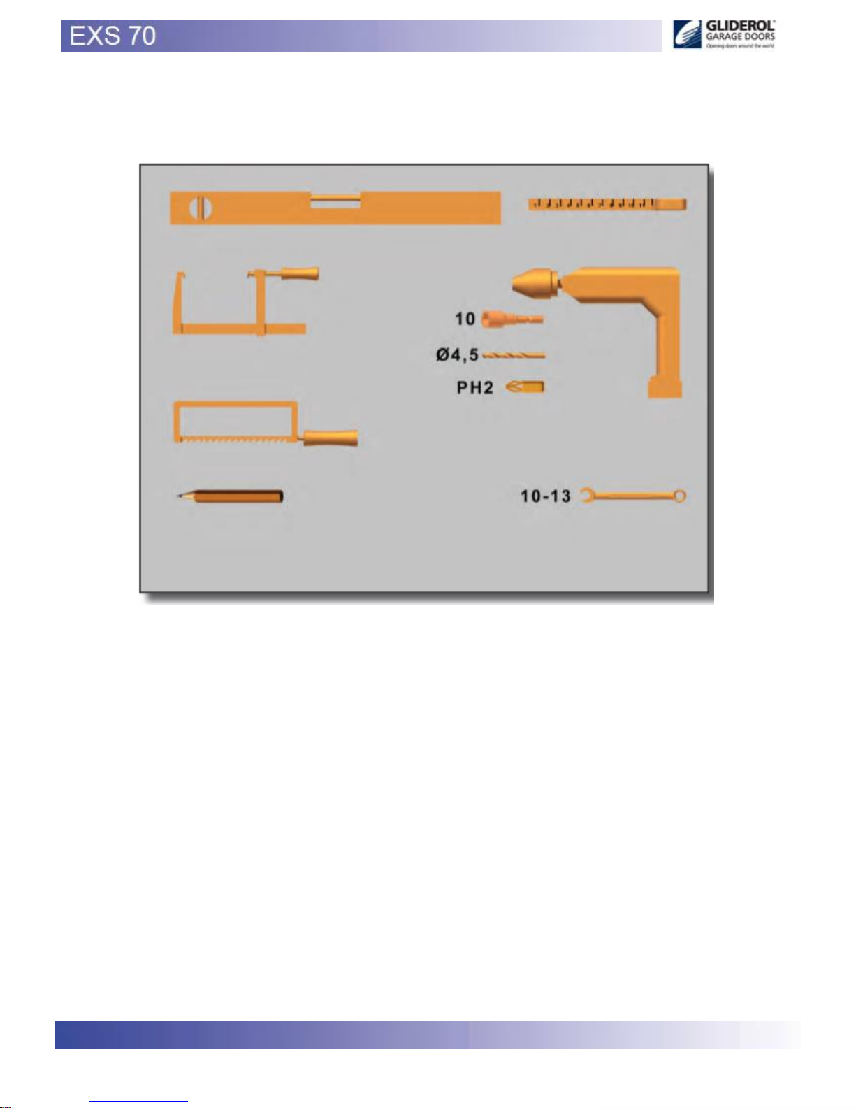
Please Note ETC Top hat
7. Tools required for installation
- Laser level and/or spirit level
- Portable drill
- Power drill or similar
- Hacksaw
- 2/4mm allen keys
- 10/13mm spanner/socket
- Stillsons
- Mole grips
- Tension pin (not supplied)
- 10 hex driver
- 4,5 steel drill
- 16.5 mm spacer blocks (supplied)
- Wall fixings (not supplied)
- Cable cutters
- 5/6 Hex head socket / tech bir
- Ph2 Phillips screwdriver
www.samsondoors.co.uk
0800 328 6250
www.samsondoors.co.uk
www.samsondoors.co.uk
0800 328 6250
www.samsondoors.co.uk
Page 5
5
www.samsondoors.co.uk
0800 328 6250
www.samsondoors.co.uk
www.samsondoors.co.uk
0800 328 6250
www.samsondoors.co.uk
Page 6
6
www.samsondoors.co.uk
0800 328 6250
www.samsondoors.co.uk
www.samsondoors.co.uk
0800 328 6250
www.samsondoors.co.uk
Page 7
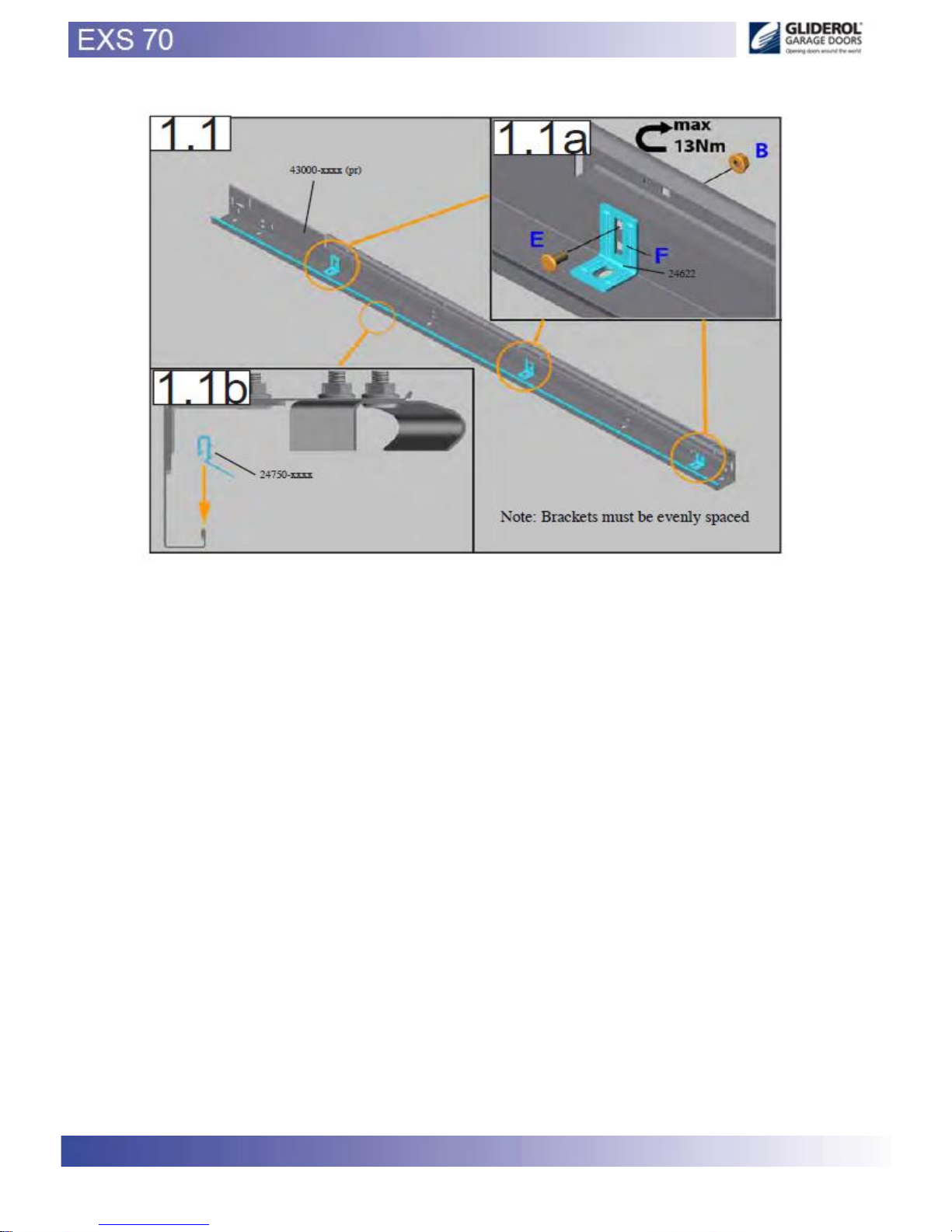
7
www.samsondoors.co.uk
0800 328 6250
www.samsondoors.co.uk
www.samsondoors.co.uk
0800 328 6250
www.samsondoors.co.uk
Page 8
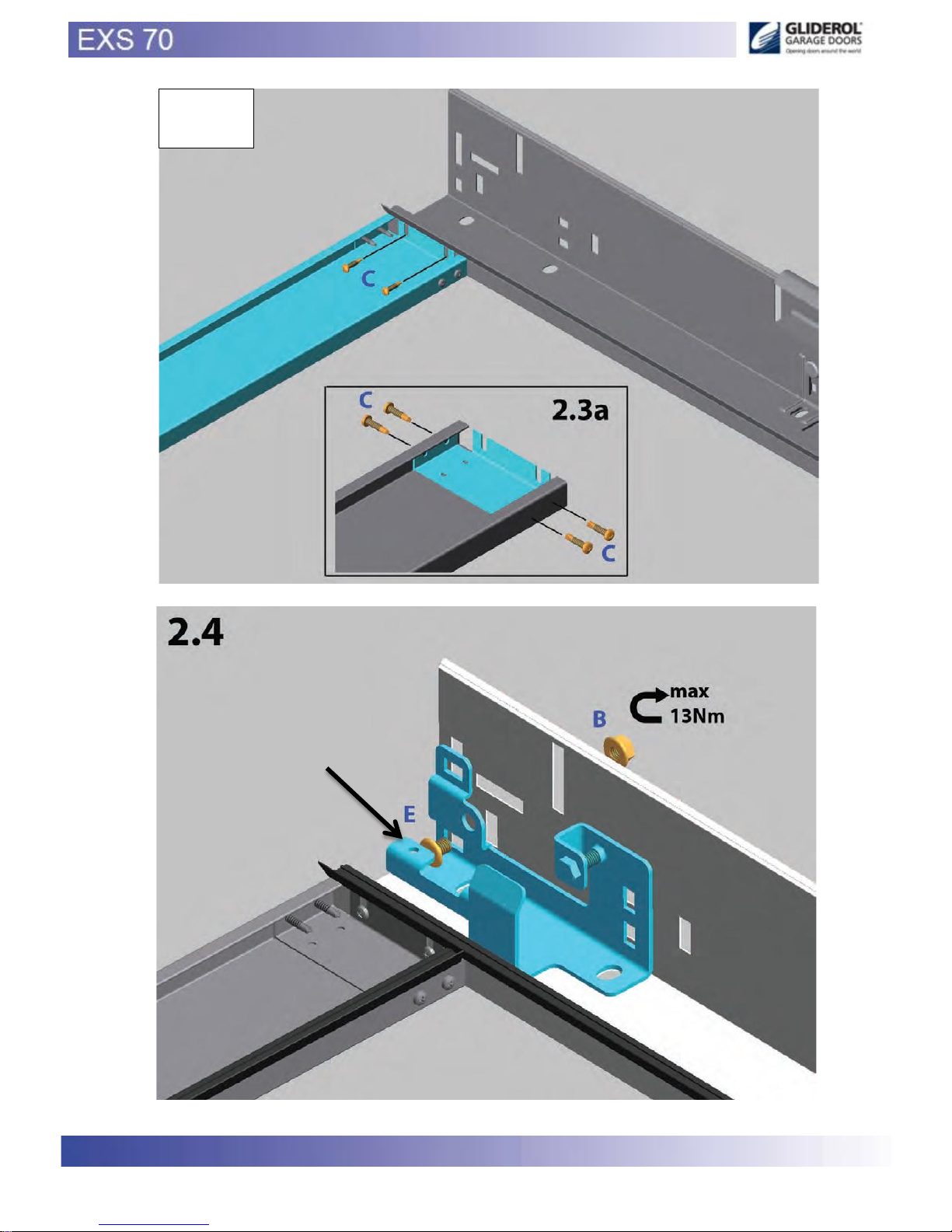
8
NOTE “C” is pre fixed screws
AA (115001) – BB (115002)
1.2
www.samsondoors.co.uk
0800 328 6250
www.samsondoors.co.uk
www.samsondoors.co.uk
0800 328 6250
www.samsondoors.co.uk
Page 9
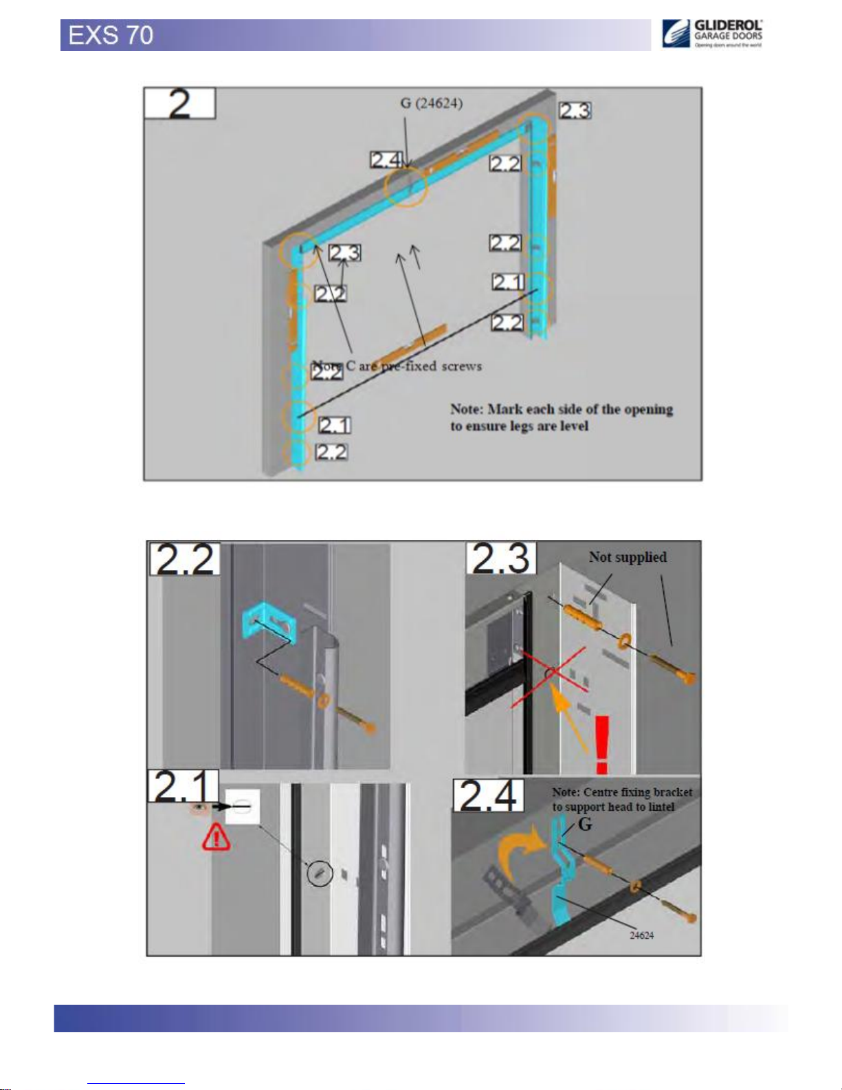
9
www.samsondoors.co.uk
0800 328 6250
www.samsondoors.co.uk
www.samsondoors.co.uk
0800 328 6250
www.samsondoors.co.uk
Page 10
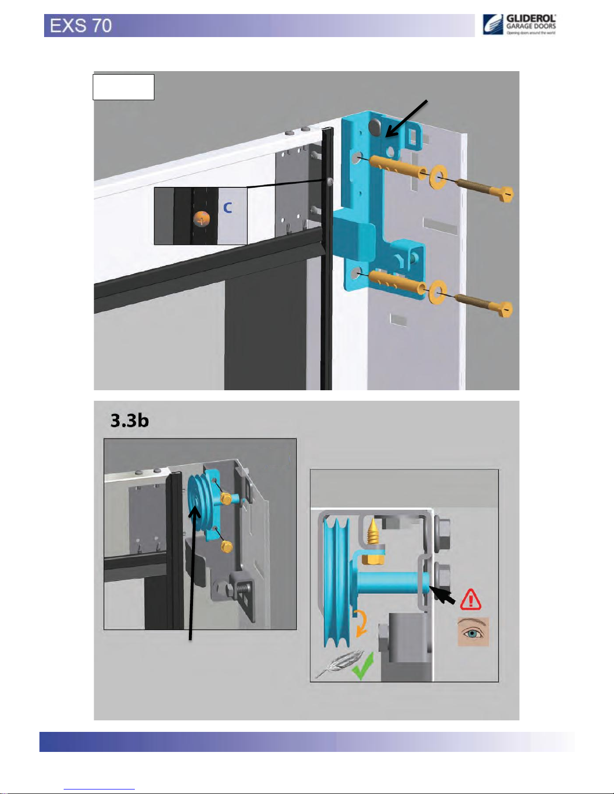
10
Before fitting panels ensure
weather seal is screwed
AA - BB
CC (115003) – DD (115004)
www.samsondoors.co.uk
0800 328 6250
www.samsondoors.co.uk
www.samsondoors.co.uk
0800 328 6250
www.samsondoors.co.uk
Page 11
11
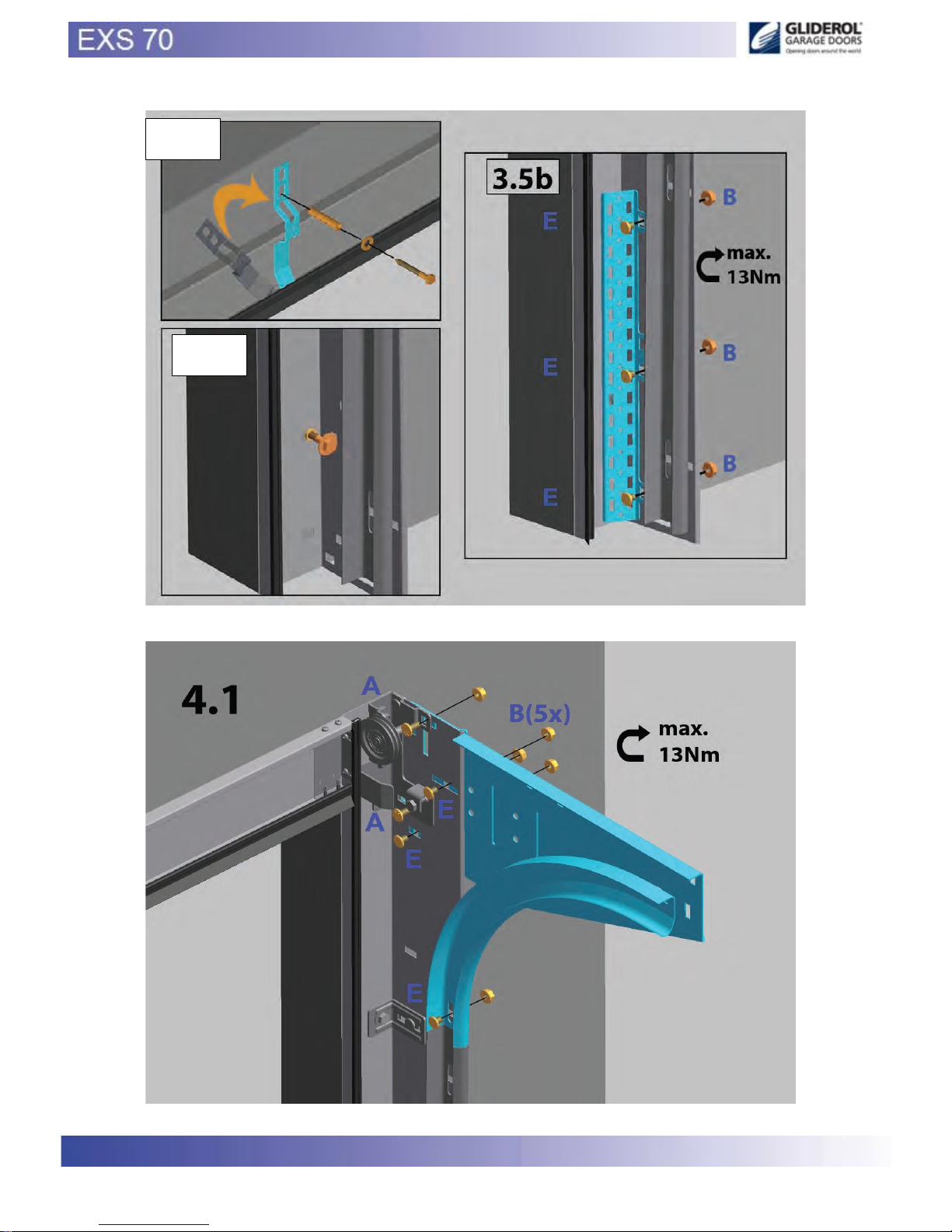
G (24624)
Pre-fitted springs
connection plates
115005
www.samsondoors.co.uk
0800 328 6250
www.samsondoors.co.uk
www.samsondoors.co.uk
0800 328 6250
www.samsondoors.co.uk
Page 12
12
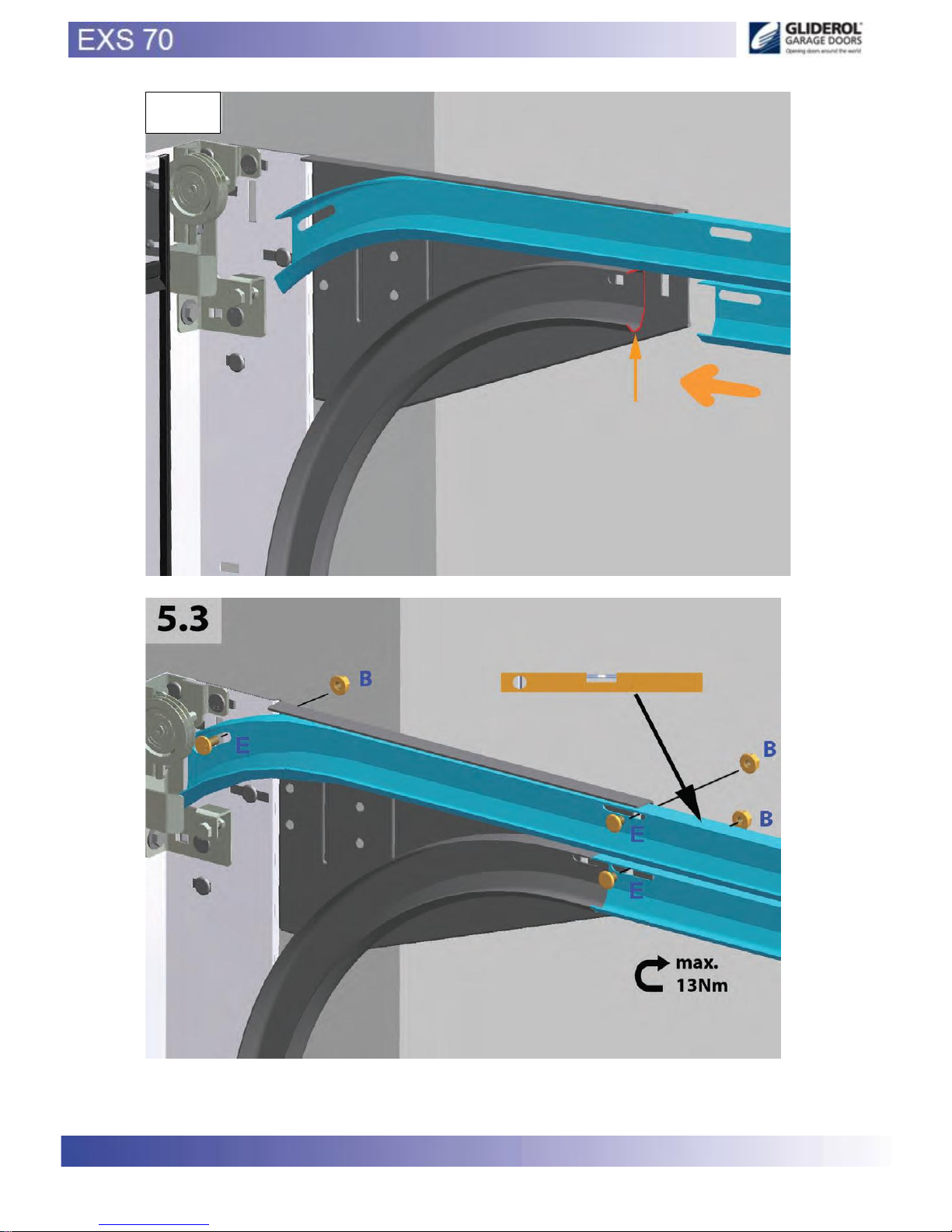
PLEASE NOTE
TRACK MAY DIFFER FROM THAT SHOWN IN DIAGRAM
Attach curve to guide using nuts and bolts E and B
www.samsondoors.co.uk
0800 328 6250
www.samsondoors.co.uk
www.samsondoors.co.uk
0800 328 6250
www.samsondoors.co.uk
Page 13
13
www.samsondoors.co.uk
0800 328 6250
www.samsondoors.co.uk
www.samsondoors.co.uk
0800 328 6250
www.samsondoors.co.uk
Page 14
14
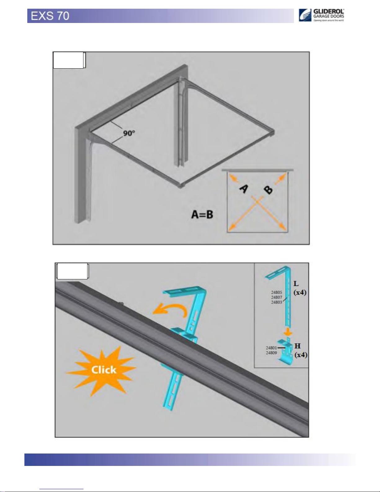
NOTE: Ensure diagonal dimensions (A=B) are exactly square and corners are 90 degrees
www.samsondoors.co.uk
0800 328 6250
www.samsondoors.co.uk
www.samsondoors.co.uk
0800 328 6250
www.samsondoors.co.uk
Page 15
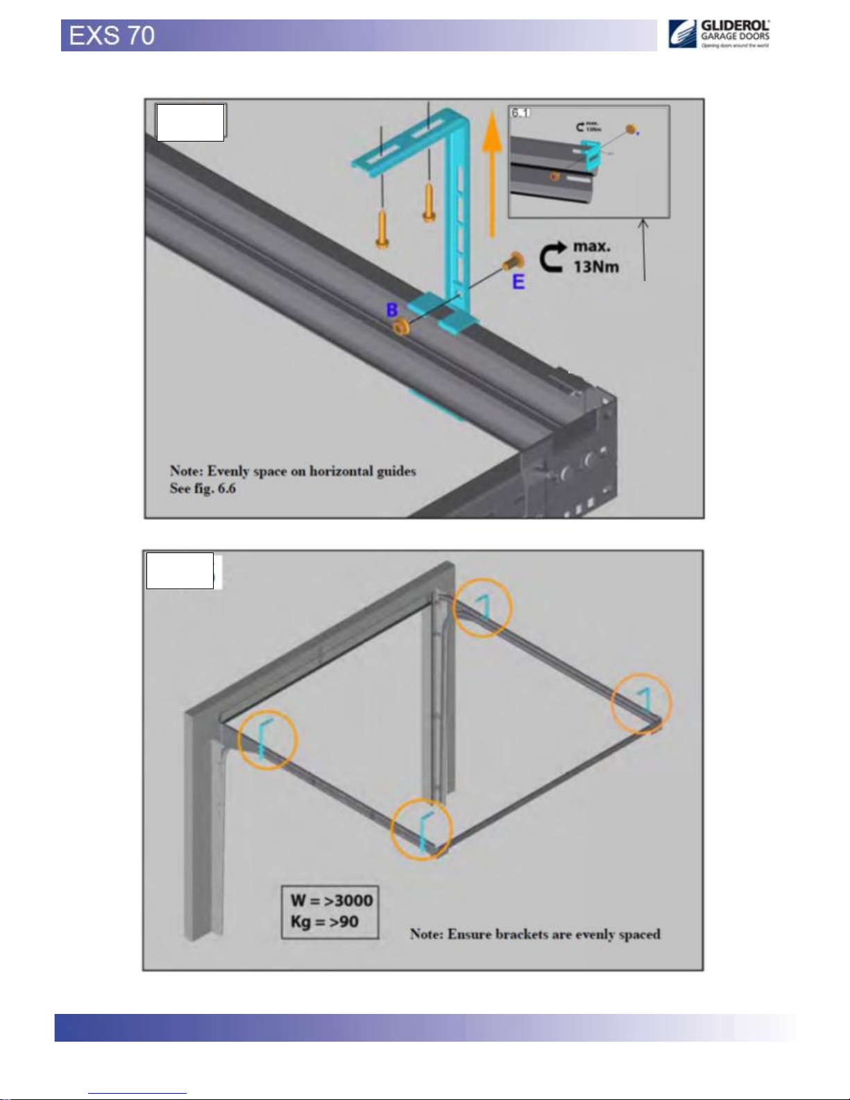
15
On Side Mount this
bracket is to be used
24622
www.samsondoors.co.uk
0800 328 6250
www.samsondoors.co.uk
www.samsondoors.co.uk
0800 328 6250
www.samsondoors.co.uk
Page 16
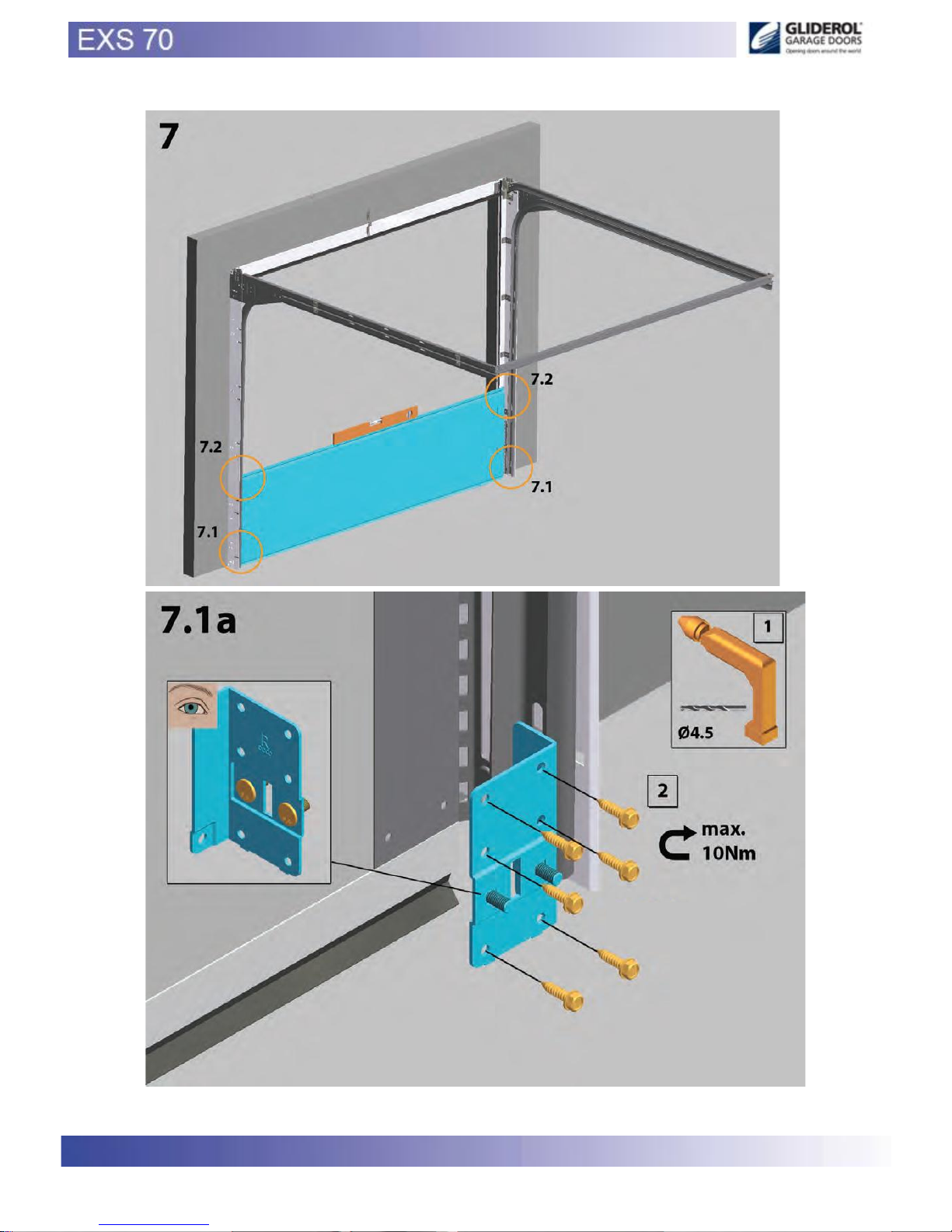
16
A 14019 x 4
D 14027 x 2
T (25052)
www.samsondoors.co.uk
0800 328 6250
www.samsondoors.co.uk
www.samsondoors.co.uk
0800 328 6250
www.samsondoors.co.uk
Page 17
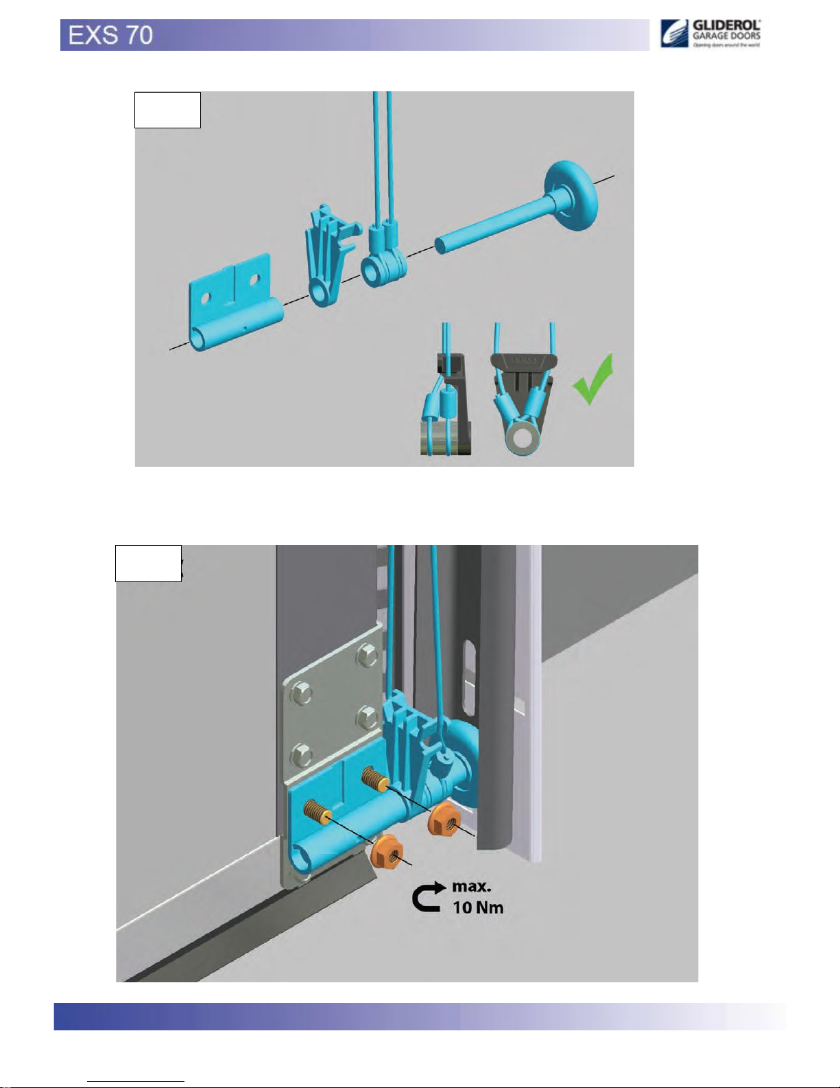
17
T 25052 – Roller
carrier
JJ (115011)
V 1152 xx
U 15008.1
PLEASE NOT
When installing bottom rollers (L/hand + R/hand) ensure panel is evenly
spaced between guides using the “Distance Rings” supplied
www.samsondoors.co.uk
0800 328 6250
www.samsondoors.co.uk
www.samsondoors.co.uk
0800 328 6250
www.samsondoors.co.uk
Page 18
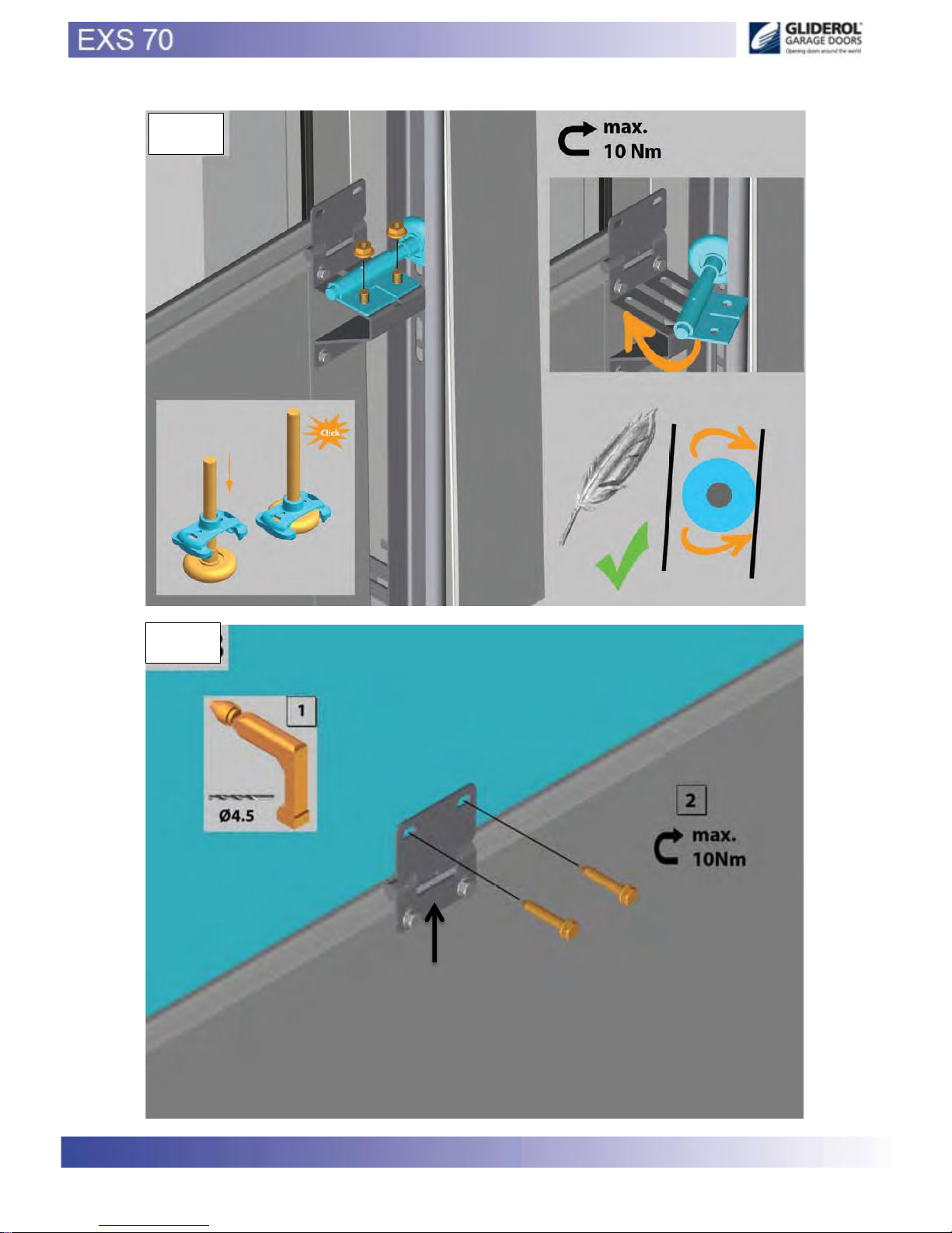
18
A
A
W (25333)
PLEASE NOT
When building stack (panel) use distance rings to ensure panels are equil
between the guides.
www.samsondoors.co.uk
0800 328 6250
www.samsondoors.co.uk
www.samsondoors.co.uk
0800 328 6250
www.samsondoors.co.uk
Page 19
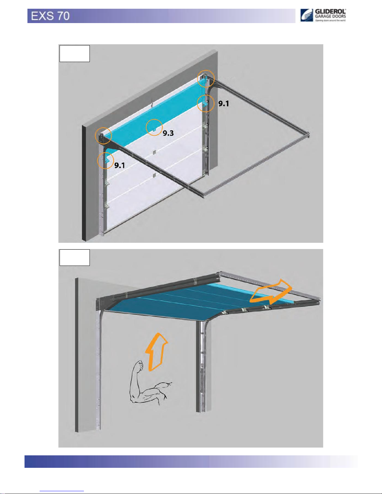
19
PLEASE NOT
When installing bottom rollers (L/hand + R/hand) ensure panel is evenly
spaced between guides using the “Distance Rings” supplied
www.samsondoors.co.uk
0800 328 6250
www.samsondoors.co.uk
www.samsondoors.co.uk
0800 328 6250
www.samsondoors.co.uk
Page 20
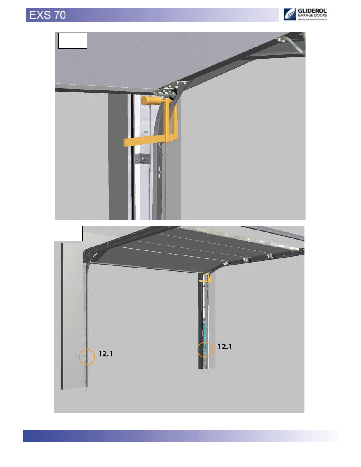
20
www.samsondoors.co.uk
0800 328 6250
www.samsondoors.co.uk
www.samsondoors.co.uk
0800 328 6250
www.samsondoors.co.uk
Page 21
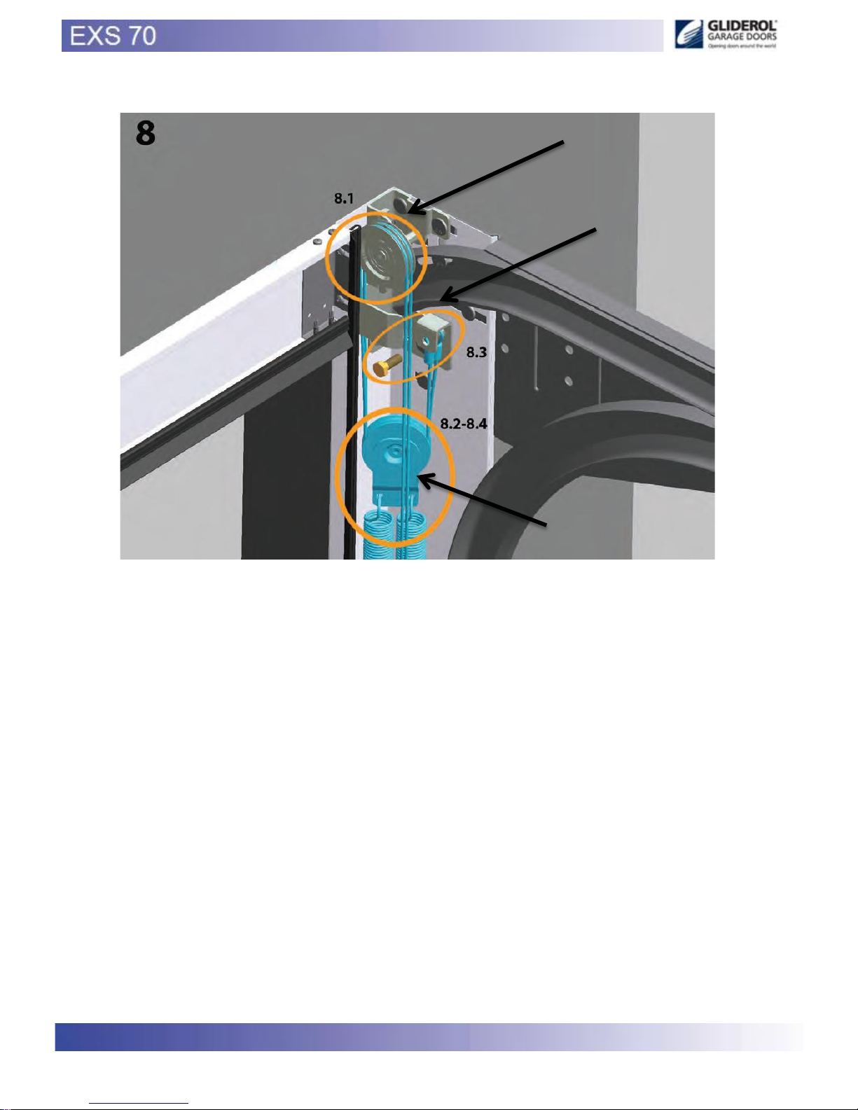
21
CC - DD
AA - BB
FF (115007)
www.samsondoors.co.uk
0800 328 6250
www.samsondoors.co.uk
www.samsondoors.co.uk
0800 328 6250
www.samsondoors.co.uk
Page 22
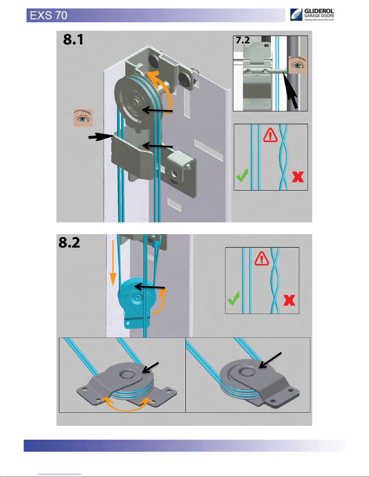
22
CC - DD
AA - BB
FF
FF
FF
www.samsondoors.co.uk
0800 328 6250
www.samsondoors.co.uk
www.samsondoors.co.uk
0800 328 6250
www.samsondoors.co.uk
Page 23
23
www.samsondoors.co.uk
0800 328 6250
www.samsondoors.co.uk
www.samsondoors.co.uk
0800 328 6250
www.samsondoors.co.uk
Page 24
24
EE (115006)
www.samsondoors.co.uk
0800 328 6250
www.samsondoors.co.uk
www.samsondoors.co.uk
0800 328 6250
www.samsondoors.co.uk
Page 25
25
EE
www.samsondoors.co.uk
0800 328 6250
www.samsondoors.co.uk
www.samsondoors.co.uk
0800 328 6250
www.samsondoors.co.uk
Page 26
26
14
www.samsondoors.co.uk
0800 328 6250
www.samsondoors.co.uk
www.samsondoors.co.uk
0800 328 6250
www.samsondoors.co.uk
Page 27
27
10. Handover
Handover the following documents to advise the end user:
- This manual (assembly, maintenance and disassembly)
- Declaration of conformity (in accordance with EN-13241-1) for automation if supplied (see 11)
- Inform the end user how to handle in case of malfunctions
10.1. First use
The first use of the garage door has to be carried out by an installer. After that the users can be instructed.
For more information refer to the user guide.
11 Electric operator (optional)
Mount the operator according the supplier’s manual.
NOTE:
In case of power failure it should be possible to unlock the door using the emergency release from the operator .
The door leaf may only in that case, be operated with a handle.
If there is no second entrance to the garage, we recommend an external release lock (art 60011) be fitted.
Do not fit a pull cord, shoot bolt or lock to an electrically operated door .
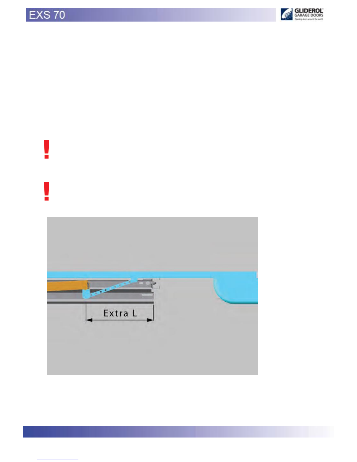
Ensure that the horizontal tracks are long enough for the electrically operator, this is with reference to the
operator drawbar (see below).
In the event that the tracks are too short, a longer horizontal track kit should be used.
www.samsondoors.co.uk
0800 328 6250
www.samsondoors.co.uk
www.samsondoors.co.uk
0800 328 6250
www.samsondoors.co.uk
Page 28

28
11.1 Operator settings
Adjustment to the operator should be carried out in accordance with the operator manufacturer’s manual.
Please note that our hardware kits have been CE approved for use with the operators specified in our ITT report
and enclosure B. Should a different
operator be chosen, then the installer must carry out a peak force analysis in accordance with EN 12445 and EN
12453.
12 Disassembly
The door should be disassembled in the reverse sequence to the assembly manual.
12.1 Disposal
All parts of this garage door can be easily disposed of.
Please consult your local authorities on this matter
13 Maintenance
In accordance with EU standards, sectional overhead doors should be checked, from the first time of use, based
on the indicated service by the installer.
This inspection service has to be recorded written.
This inspection service should be carried out by an approved installer cq company.
Directly after installing:
1) Lubricate the tracks (advice: PTFE spray) By Installer
2) Lubricate bearings, and rollers (advice: PTFE spray) By Installer
3) Lubricate pins of the hinges from intermediate- and side-hinges (advice: PTFE spray) By Installer
4) Lubricate sealing rubbers (advice: special rubber grease or talcum powder By Installer
After 3 months: This may be chargeable by the installer
1) Re-tensioning springs (relaxation springs) By Installer
2) Visual inspection By Installer
Every 6 months or every 750 door cycles:
1) Remove debris from the door and surroundings By: user
2. Lubricate the tracks (advice: PTFE spray) By: user
3. Lubricate bearings, shafts and rollers (advice PTFE spray) By: user
4. Lubricate pins of the hinges from intermediate- and side-hinges (advice: PTFE spray) By: user
5. Lubricate sealing rubbers (advice: special rubber grease or talcum powder) By: user
6. Clean the panels (advice: shampoo for car cleaning with water),
do not use aggressive detergents By: user
7. Wax the panels (advice: car wax) By: user
Every 12 months or every 1500 door cycles:
1. Check the cables, the end connections, bottom brackets on wear or damages By Installer
2. Check the balance of the door By Installer
3. Check the pulley (if present) for wear or damages By Installer
4. Check the rollers for wear and damages By Installer
5. Check the closing forces of the main closing edge By Installer
6. Check the suspension from the horizontal track to the ceiling By Installer
7. Check the weather strips for wear or damages By Installer
8. Check the bottom seal for wear or damages By Installer
9. Check the rubber seals on the top panel for wear of damage By Installer
www.samsondoors.co.uk
0800 328 6250
www.samsondoors.co.uk
www.samsondoors.co.uk
0800 328 6250
www.samsondoors.co.uk
 Loading...