

Page 1
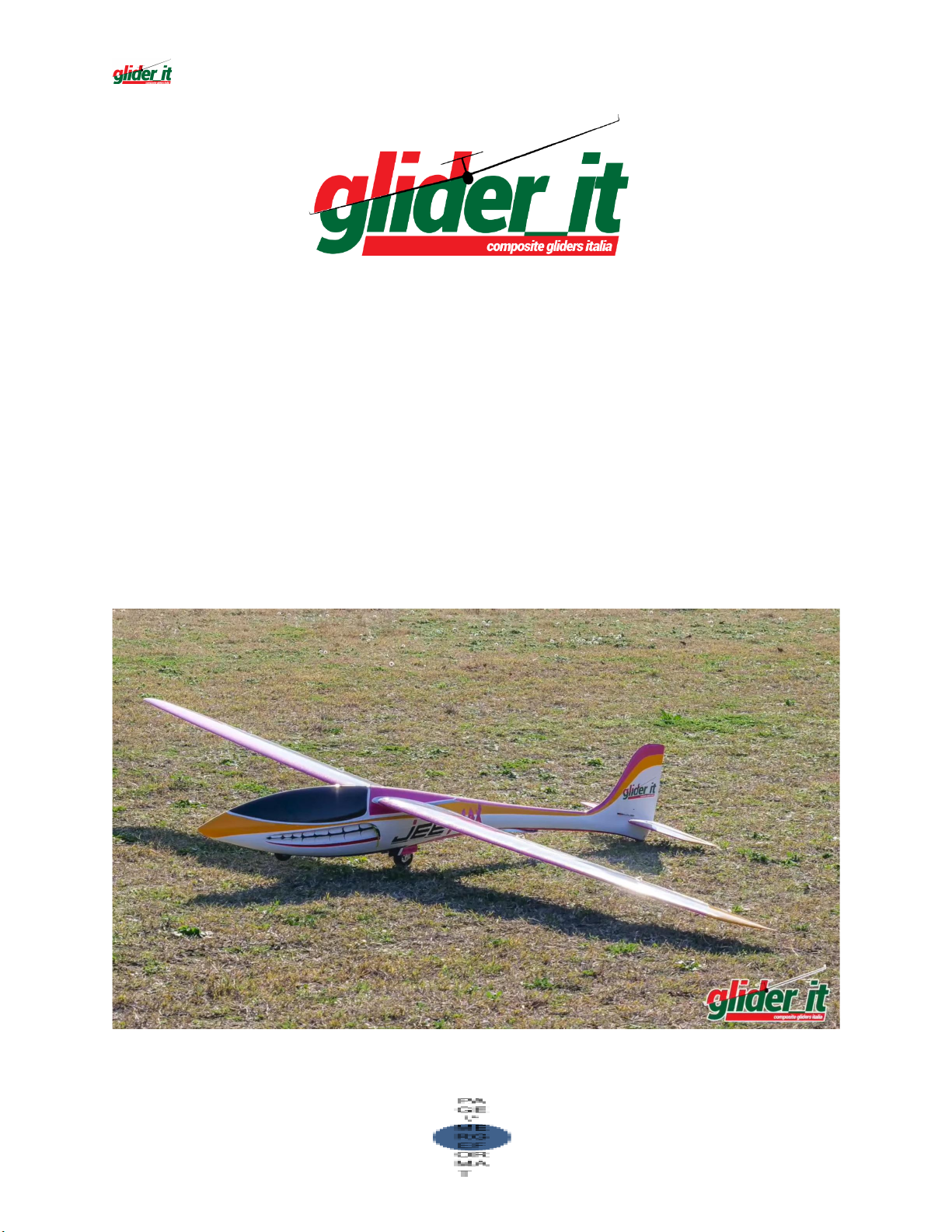
JeeMAX
1
INSTRUCTION MANUAL
Page 2

SUMMARY
2
Introduction, Safety Information 3
Kit parts , technical data 4
Functions, Servos , Set Up 5
Fuselage 6
Servo Rudder 8
Servo Elevator 11
Turbine Prop 12
Fuel Tank 17
Baseplate installation 20
Canopy Base (Cockpit) 21
Wings ang moving parts 22
Wings lock 27
Conclusion 28
Page 3

INTRODUCTION
3
JeeMAX was made possible by the great experience of the team
Glider-it team development department have developed a TOP
Glider-Jet that can be make the takeoff from the ground. It can host a
kerosene turbine of 78mm of diameter but for now we have certified
the Kingteck k65g4.
The JeeMAX is supplied with a retractable landing gear included with
ready installed support, you need only install the servos (with supports
provided) , the special tank ( provided), and your radio system ...
JeeMAX is capable of taking off from the ground thanks to its landing
gear and can also be used on asphalt runways for landing!, carbon
square wing joiner and bottom hinged aileron and flaps with lips.
Jeemax immediately demonstrated great aerobatic flying skills both
with engine and gliding, and a formidable handling.
SAFETY INFORMATION
Even if we do for every model a careful quality control, there may be
some imperfection.
Therefore, we also ask you to check all the parts before use; If a
part/component is not conforming/defective, we will be available to
examine and replace it after checking. In this case do not hesitate to
contact us.
All the parts worked by the customer are excluded by replacement.
ATTENTION!! These instructions want to help you to complete the
assembling of JeeMAX, as per our suggestions/methods.
Servos and accessories we suggest to use can be obviously replaced by
other similar items of other brands/producers
RC gliders are not toys; their assembling and use needs technical
knowledge and craftsmanship.
Page 4
Attenzione!
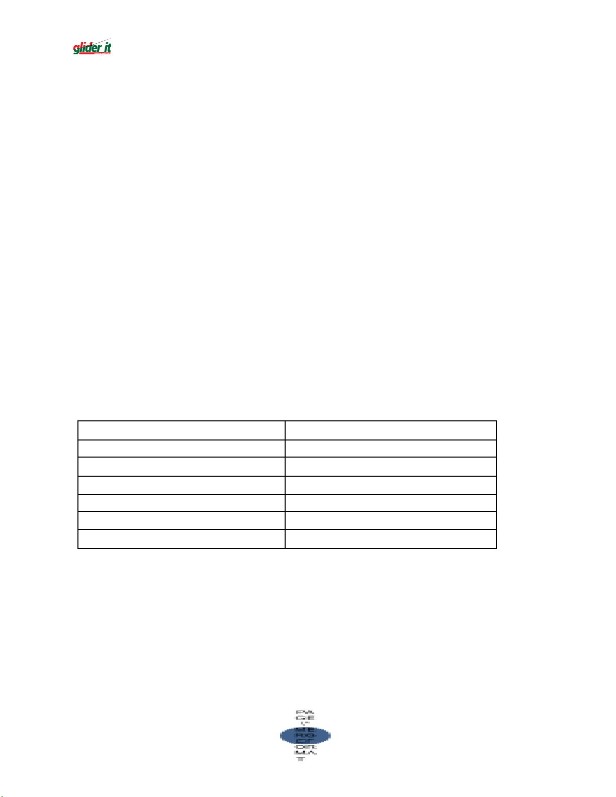
Wingspan
3500 mm
Fuselage Length
1980 mm
Wing Area
91 dm2
Weight
9000 g
Wing Load (= >)
91 g/dm2
Wing Profile
by Glider-IT
Center Of Gravity (CG)
130 mm *
4
I modelli RC, in particolare gli aeromodelli, non sono giocattoli.
Mistakes and negligence in building and flying may cause damage to the
people and things.
We point out these dangers because we are not responsible for your
assembling work, maintenance and flight of your RC glider.
KIT PARTS
1 wings (left/right), 1 wing joiner, 1 fuselage, 1 elevator, 1 rudder, 1
canopy, 1 wooden base plate, 6 servo supports + covers, 1 set control
horn fiberglass, 1 tank + kit fuel cap, 1 retractable landing gear + cover, 1
front fix landing gear, 1 turbine guides, 1 exhaust tube
Turbine-ready fuselage, retractable landing gear ready to be installed,
fixed front landing gear installed, rudder support installed.
TECHNICAL DATA
* measure the center of gravity with an empty tank.
Page 5
Functions – servos– set-up
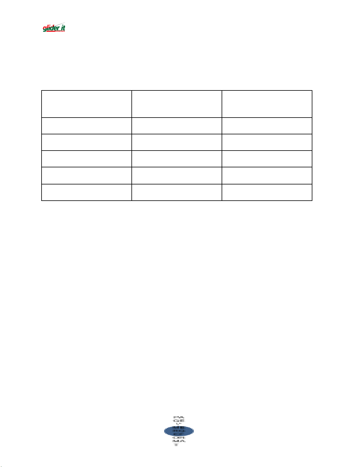
Function
Servo
(suggested)
Excursion
Ailerons
KST A12
12 mm
Flaps
KST A12
12 mm
Rudder
KST A12
12 mm
Tailplane
KST X10 Pro
10 mm
Landing gear
KST A12
12 mm
5
Jeemax servo travel :
Aileron : ±15 mm expo 40%
Flaperon: A±15 mm F±30 mm expo 40%
Rudder: ±40 mm expo 55%
Elevator : ±15 mm expo 55%
Butterfly : aileron up 15mm, flap down 35mm, elevator
compensation 12% down
Takeoff : flap and aileron 5mm down
Speed : all value 1/3 less (66% of std travel)
Page 6
FUSELAGE building guide
6
We suggest to cover the fuselage with Paper-Tape (to avoid scratch
and glue dirty)
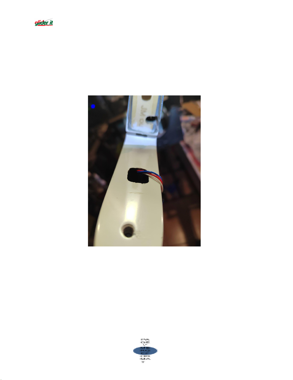
Open the hole for the servo cable in the elevator seat on the fuselage.
make hole big enough for servo connector to go through without going to
near to screw nuts
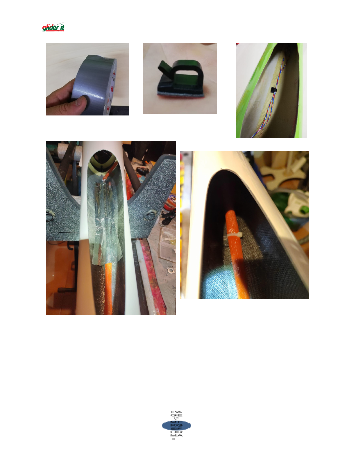
Rudder and elevator servo wire extensions must be long enough to reach
the nose of the fuselage, using big section wire. Wire must be attached to
the fuselage top either using american tape or wire holding platic clips, as
you like. lt is important to keep wire away from turbine heat.
Page 7
7
Page 8
RUDDER (MOVING PART)
8910
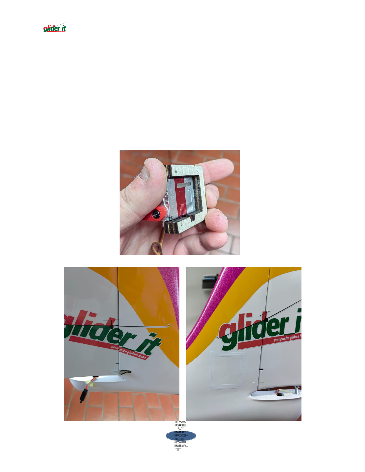
The wooden reinforcement of the vertical is already mounted in the
fuselage. It will have to accommodate the hinges for the directional.
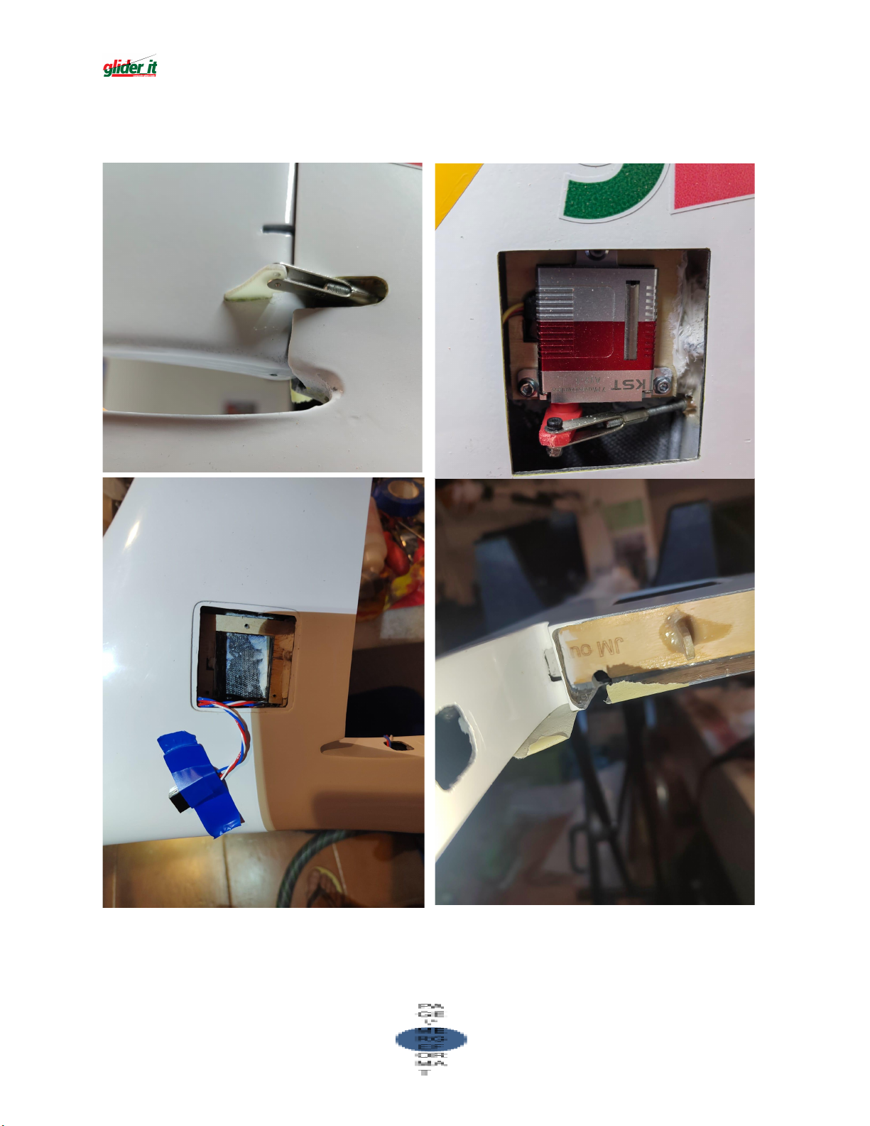
To install rudder servo use the supplied servo holder (depending on servo thickness
you may need different thickness servo mout) , servo horn and contral horn Check
accurately before gluing permanently
We suggest to not use epoxy but a heavy duty construction adhesive like saratoga
Unicum (or similar products like Pattex PL, Bostik mauntig glue, Gorilla construction
glue ); this kind of glues will withstand better to hard landings and vibrations
Page 9
Page 10
Page 11
ELEVATOR (MOVING PART)
11
For installing elevator servo use one the supplied servo holder.
Check accurately before gluing permanently
We suggest to not use epoxy but a heavy duty construction adhesive like
saratoga Unicum (or similar products like Pattex PL, Bostik mauntig glue,
Gorilla construction glue ); this kind of glues will withstand better to hard
landings and vibrations
Page 12
TURBINE PROP
12
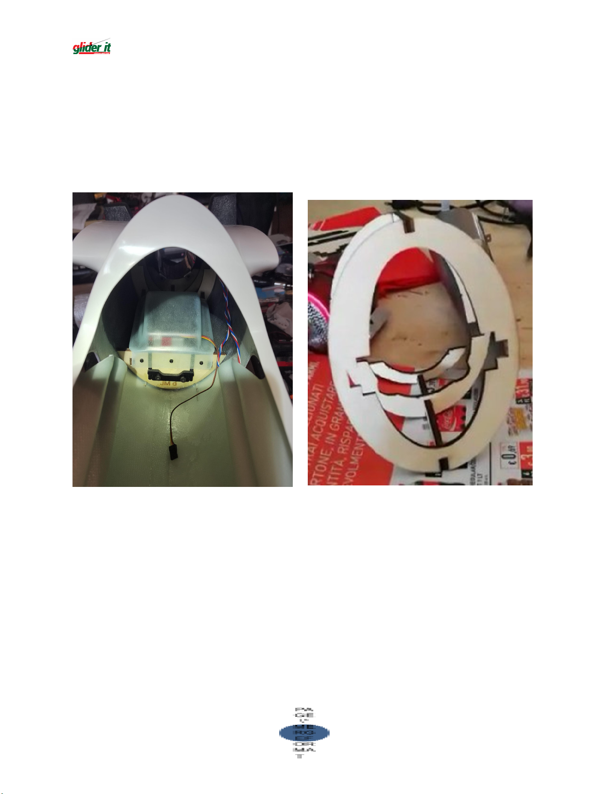
The JeeMAX fuselage will come with already installed the 3 bulkhead you
can see in the picture on the right and the 2 bulkhead for retractable
landing gear you can see in the picture on the left. The landing gear cover
is also provided to install after the retractable landing gear is secured in
place.
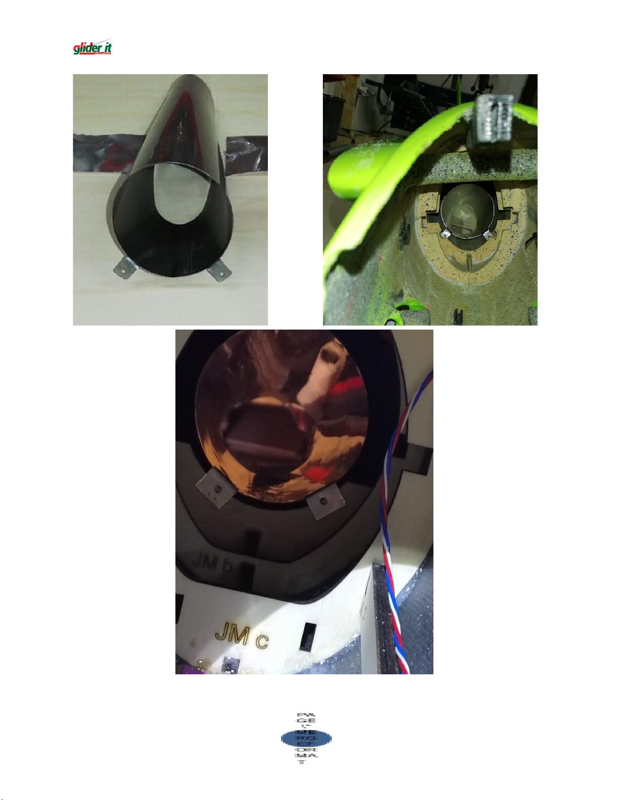
As first you will have to insert the exhaust tube and install it with two
screws going through the holes in the mounting bracket to the 3rd
bulkhead using two self-tapping screws
Page 13
13
Page 14
Now you have to install the
14
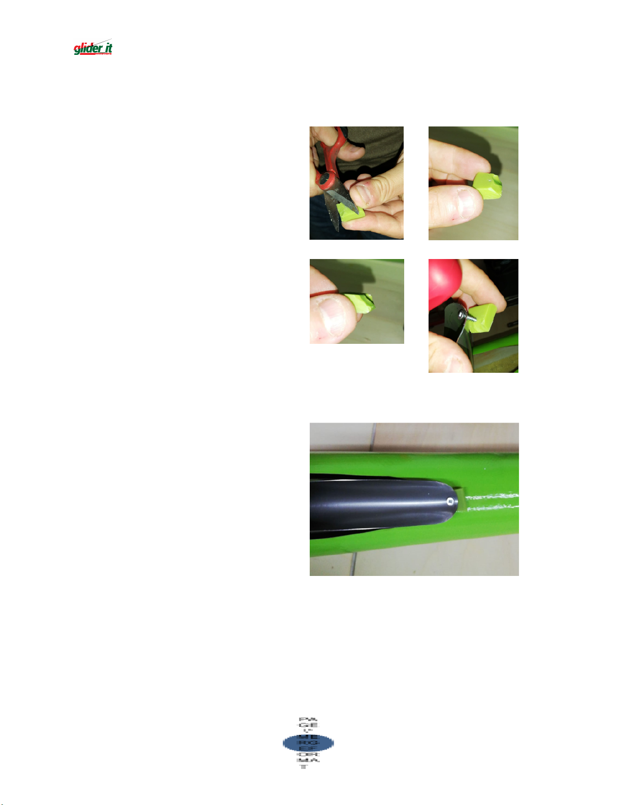
3rd screw that keep the
exhaust in position (may help
making a small hole with a
drill in the fuselage, exhaust
will come with hole already
made ) inserting the small
piece of high temperature
resistant rubber between the
exhaust and the fuselage
to make installation easier we
suggest you shape the small
piece of rubber with a bevel
like in the picture.
this will help the exhaust to
sit well in position
Page 15
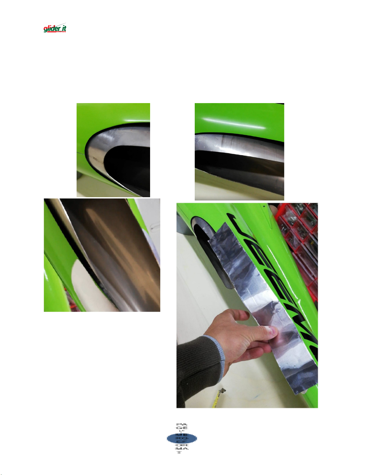
Please check the exhaust to not get in contact with the fuselage in any
15
point, in case of need sand a little the fuselage to enlarge the hole and to
have enough space IT IS ESSENTIAL THE EXHAUST MUST NOT BE IN
CONTACT WITH THE FUSELAGE ANYWHERE
Now you can apply the self
adhesive alloy foil tape to protect
the fuselage from exhaust hot air.
Shape it to have a nice contour
and apply.
Page 16
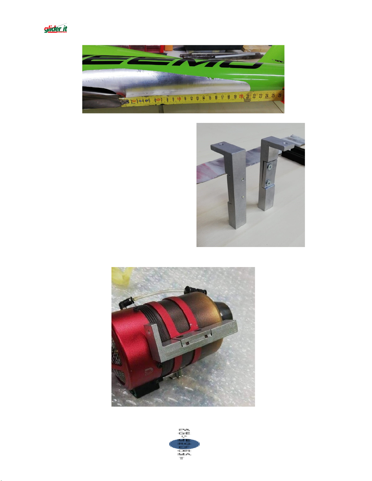
Now you can install the turbine;
16
wood bulkheads are already
installed in the fuselage. you have
to screw the two alloy rail mount
brackets supplied with the kit to
the turbine Mind one bracket will
be upward and the other
downward.
Insert the turbine in peace and
fix with the screw to the wood
bulkhead
Page 17
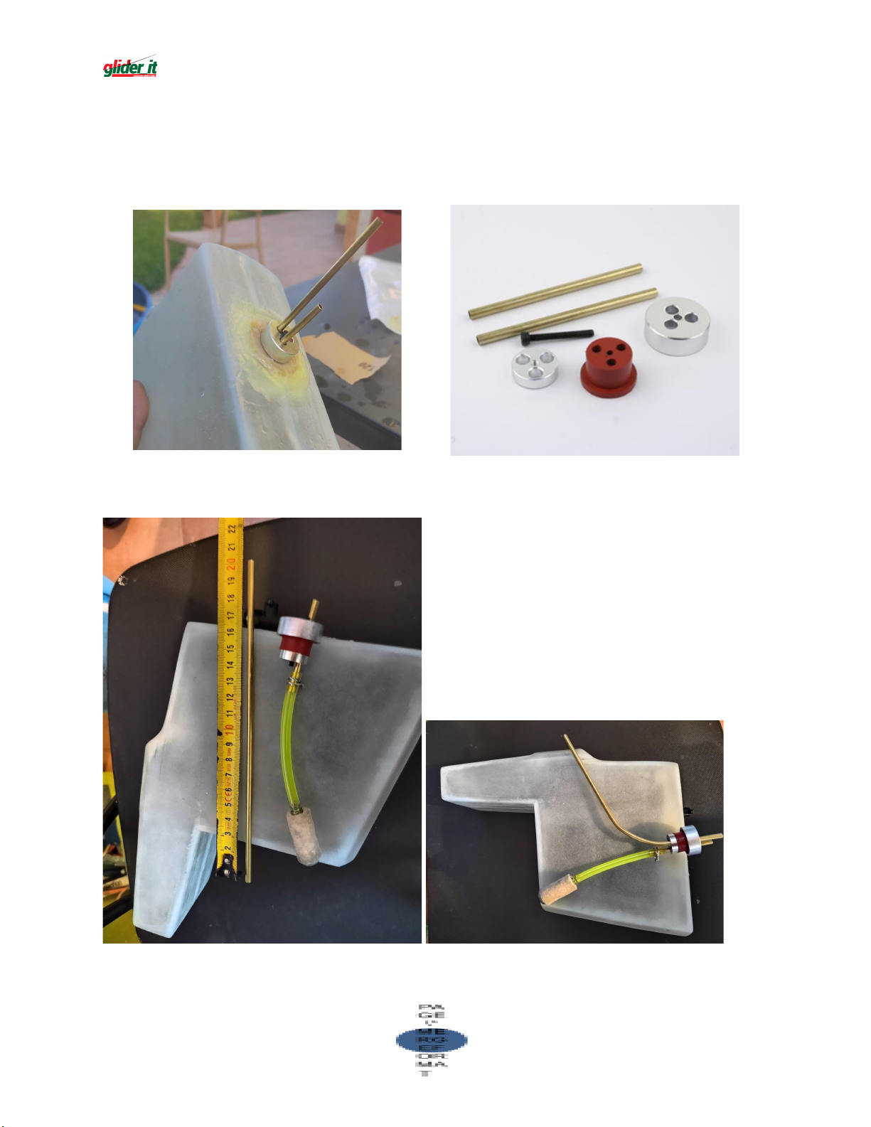
FUEL TANK
17
A special custom made fuel tank is supplied in the kit complete with tank
cap and tank mounting rails. Install tank cap and check tor a good seal , to
not have fuel leakage Tray to "dry fit" fuel tank and rails in fuselage.
You have to build a new tube for the full level. It must be 200 mm long.
You have to fold it to make it go near the high border of the tank. See
photos below.
Page 18
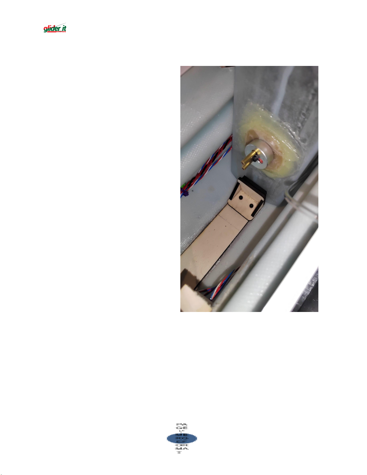
It may be necessary to sand a little the fuel tank closing lips that are going
18
inside tank rails, so that tank will fit easily inside the fuselage.
When you are satisfied with the
positioning of the tank, install the
tank STOP, provided to you, with
two screws.
Page 19
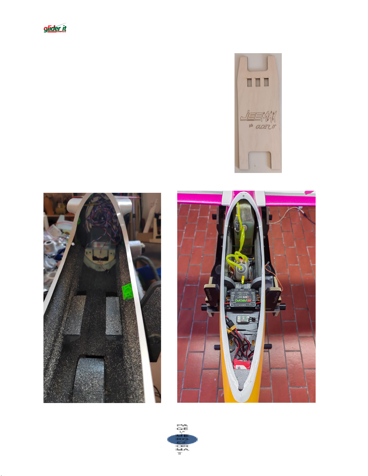
BASEPLATE INSTALLATION
19
A baseplate cnc cut is supplied
with the kit.
lnstall two small pieces of wood
about 5mm forward of the air
intake and one piece forward in
the fuselage like in the picture, so
you can attach the baseplate with
small self tapping screws.
The following images are sample of a
possible radio and accessories installation
Page 20
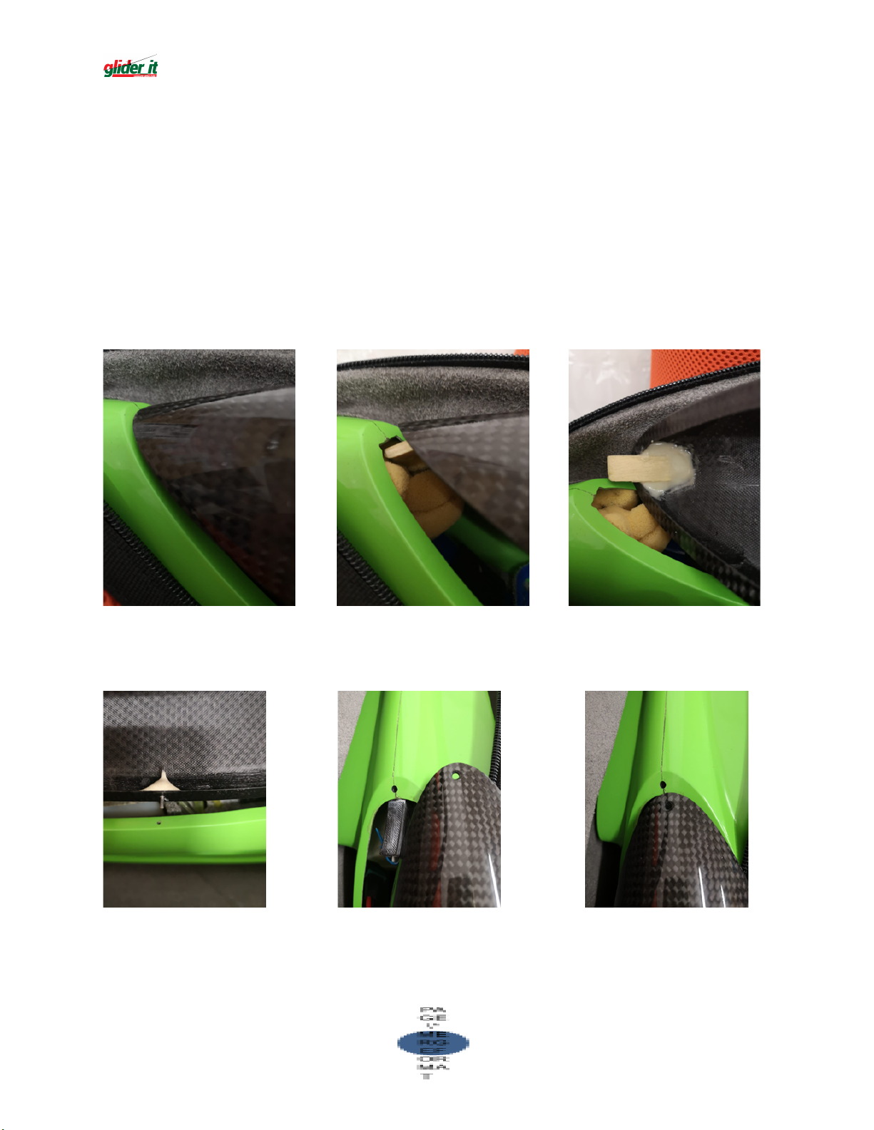
CANOPY BASE
20
The following images are samples of a possible way to install the canopy:
Glue a piece of wood to the canopy and make a suitable notch in the
fuselage install two metal pins , one on each side at about the mid of the
canopy.
Install a nut in the fuselage just above the fuel tank rail, make a hole in the
canopy tor the screw
Page 21
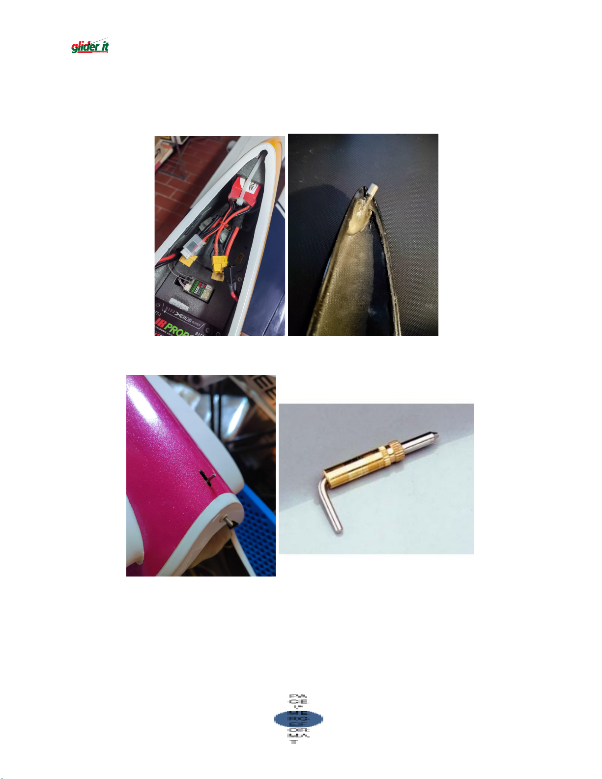
Glue a piece of wood to the canopy and make a suitable notch in the
21
fuselage install two metal pins , one on each side at about the mid of the
canopy.
Install the specific fastening tool on the opposite side of the canopy. Open a
window in the fuselage to pass the rod.
Page 22
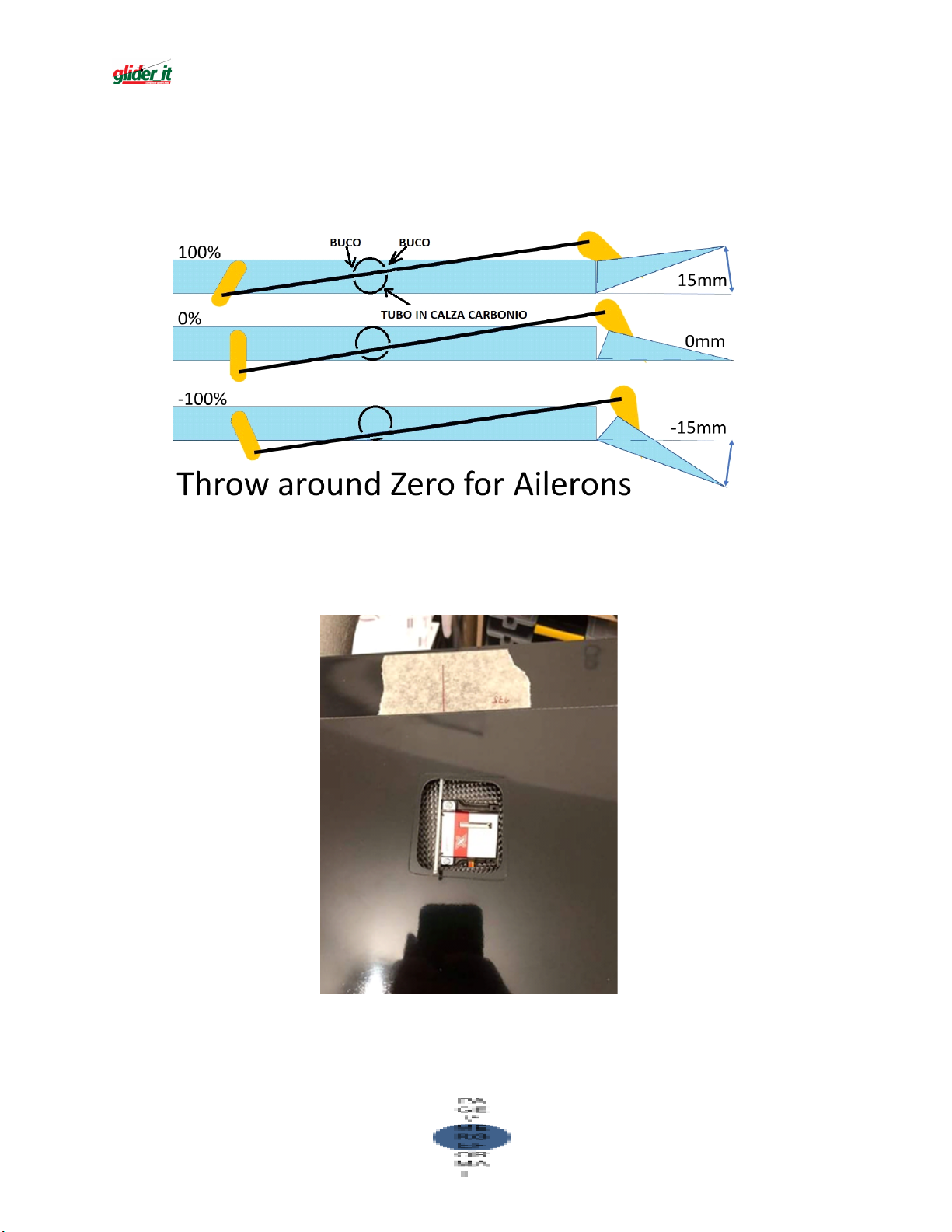
WINGS (AILERON + FLAPS CONTROLS)
22
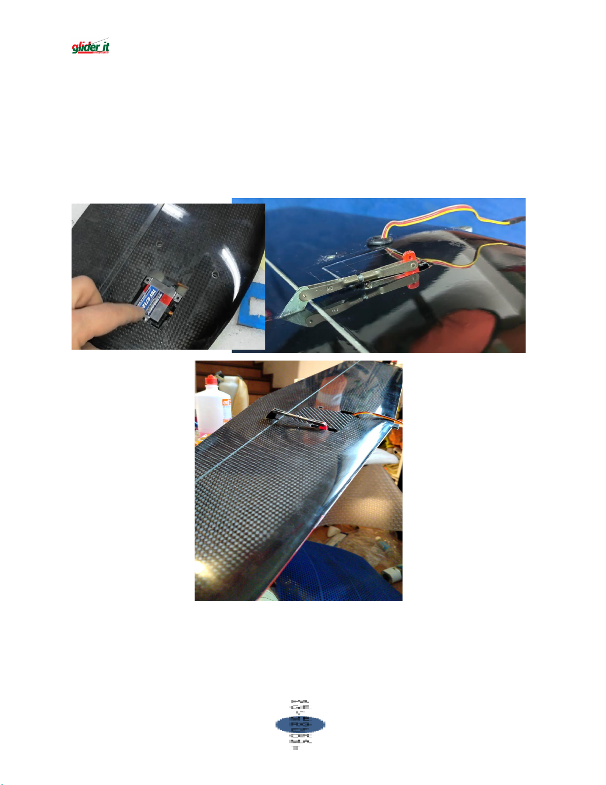
Flaps and Ailerons are hinged in the bottom side of the wings, therefore
we suggest the TOP-DRIVE system as shown in the below image
Mark the right axis position in the bottom side of the aileron and do the
same in the upper side
Page 23
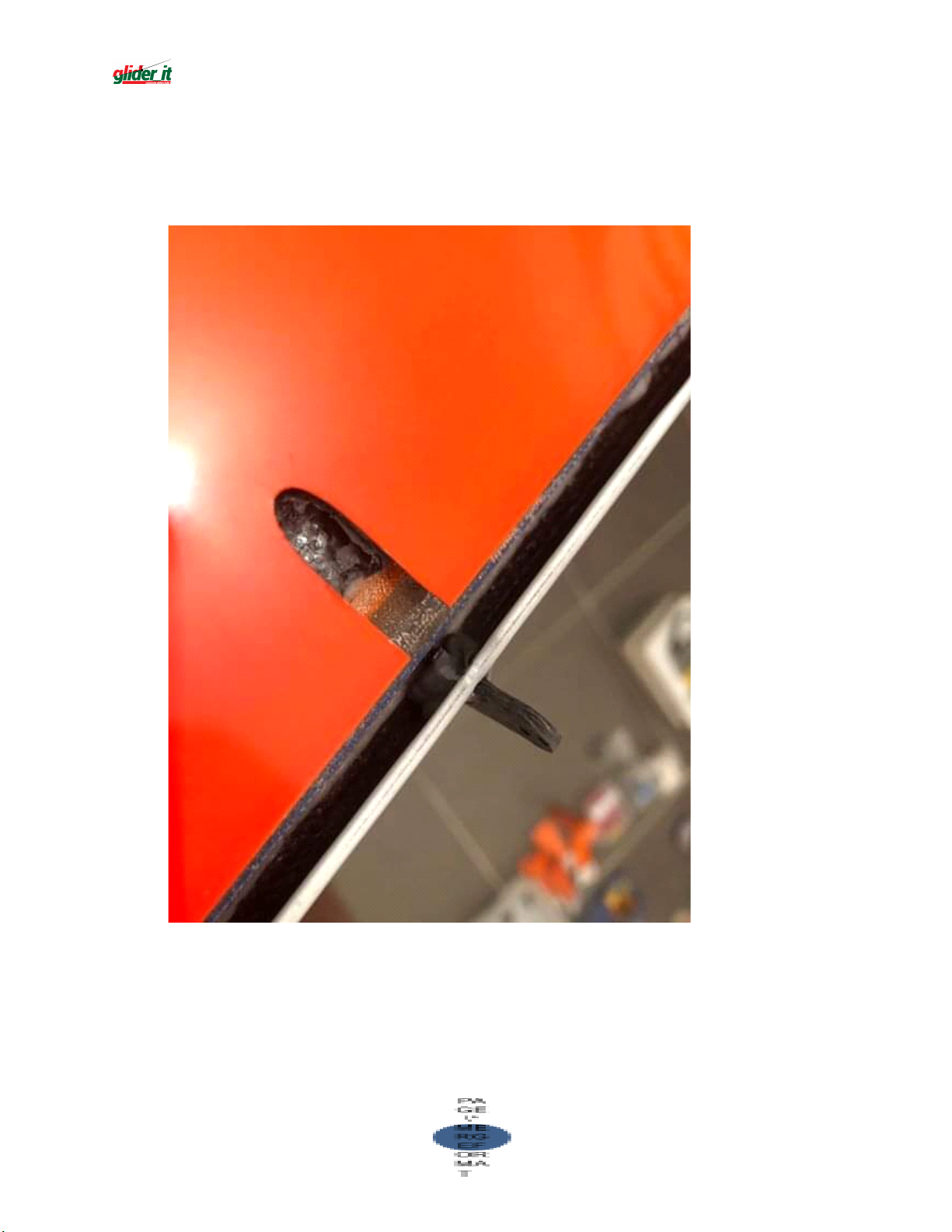
Mark the same axis position also in the upper side of the aileron; cut (with
23
Dremel) the opening for control horn and cut the “nail” opening in the
wings
Page 24
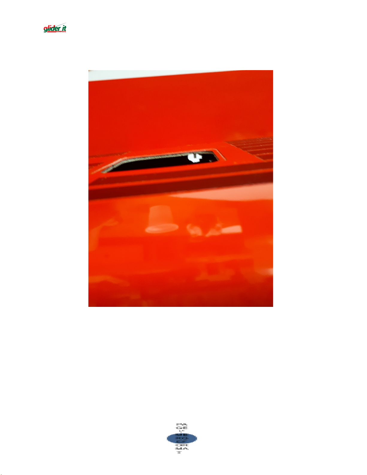
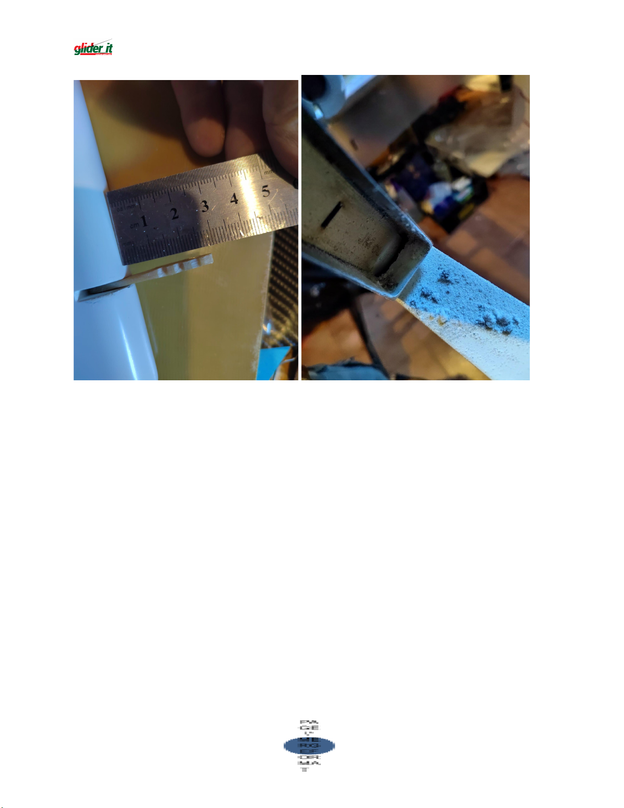
Now you have to hole the carbon tube inside the wings, as shown in the
24
picture
Test the clevis linkage + rod with the control horn.
If the movement is correct, glue the control horn.
Page 25
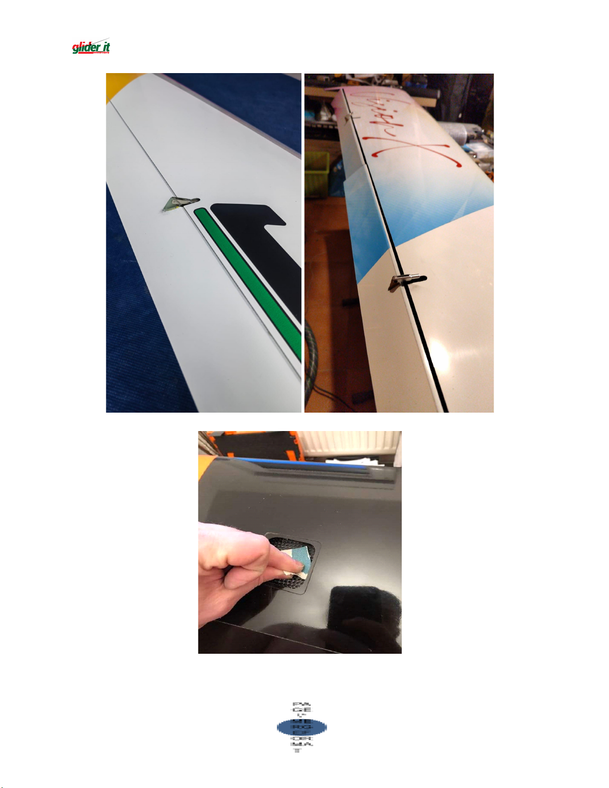
Sand the gluing surface
25
Page 26
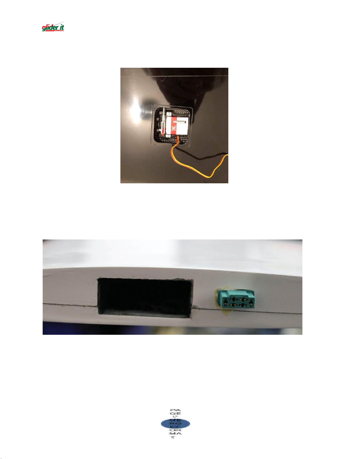
Arrange the servo and all the linkage systems; if it works properly, glue the
26
servo base to the wing.
Solder the servo cable to the MPX connector (6 pins – male) following
the scheme previously used for the female connector.
Before gluing it to the wing, check the right connection (MPX
male/female) of the winds to the fuse.
Put the servo cover over the opening, mark the cutting area with paper
tape and remove with scissor the excess part
Join the servo cover to the wings with transparent tape
Page 27
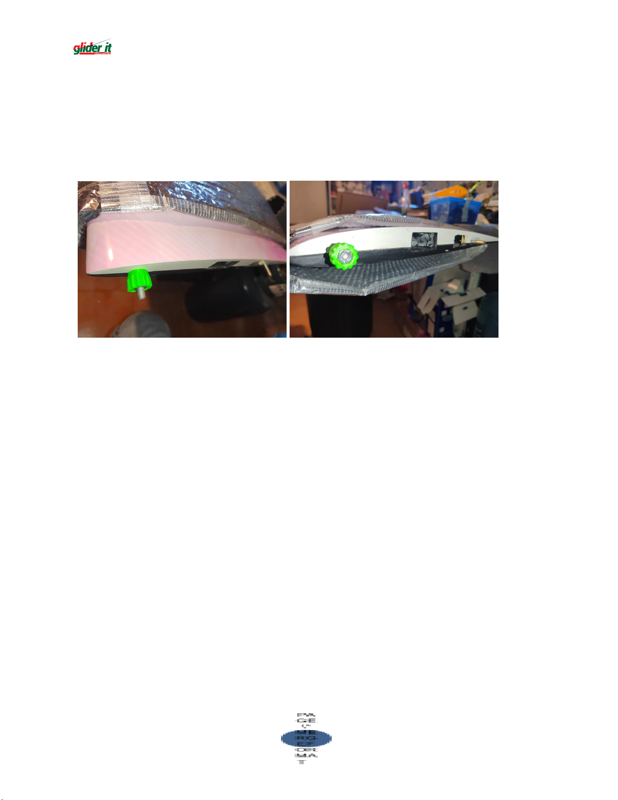
WING LOCKING SYSTEM
27
The wing locking system is already installed in the wings of the model
and there are corresponding holes in the fuselage of the JeeMAX.
Move the wings to the fuselage and screw the provided nut to close
them.
Page 28

CONCLUSIONE
28
La sicurezza è il primo requisito quando si vola con aeromodelli.
L'assicurazione RCA è obbligatoria. Accertati di avere un'adeguata
copertura assicurativa. Mantenere sempre modelli e telecomandi in
perfetto ordine. Vola responsabilmente! Rispetta le normative e le
leggi in vigore.
Ti auguriamo buon divertimento e fantastici voli con il tuo JeeMAX!
CONCLUSION
Safety is the first requirement when flying with model aircraft. RCA
insurance is mandatory. Make sure you have adequate insurance
coverage. Always keep models and remotes in perfect order. Fly
responsibly! Comply with applicable laws and regulations.
We wish you good luck and a great flight with your JeeMAX!
 Loading...