

GLIDECAM
XR-SERIES
XR-1000 / XR-2000 / XR-4000
Set-up and Operations Guide
Glidecam Industries, Inc. 23 Joseph Street, Kingston, MA 02364
Customer Service Line 1-781-585-7900
COPYRIGHT 2015 GLIDECAM INDUSTRIES,Inc. ALL RIGHTS RESERVED
MANUAL
Manufactured in the U.S.A.

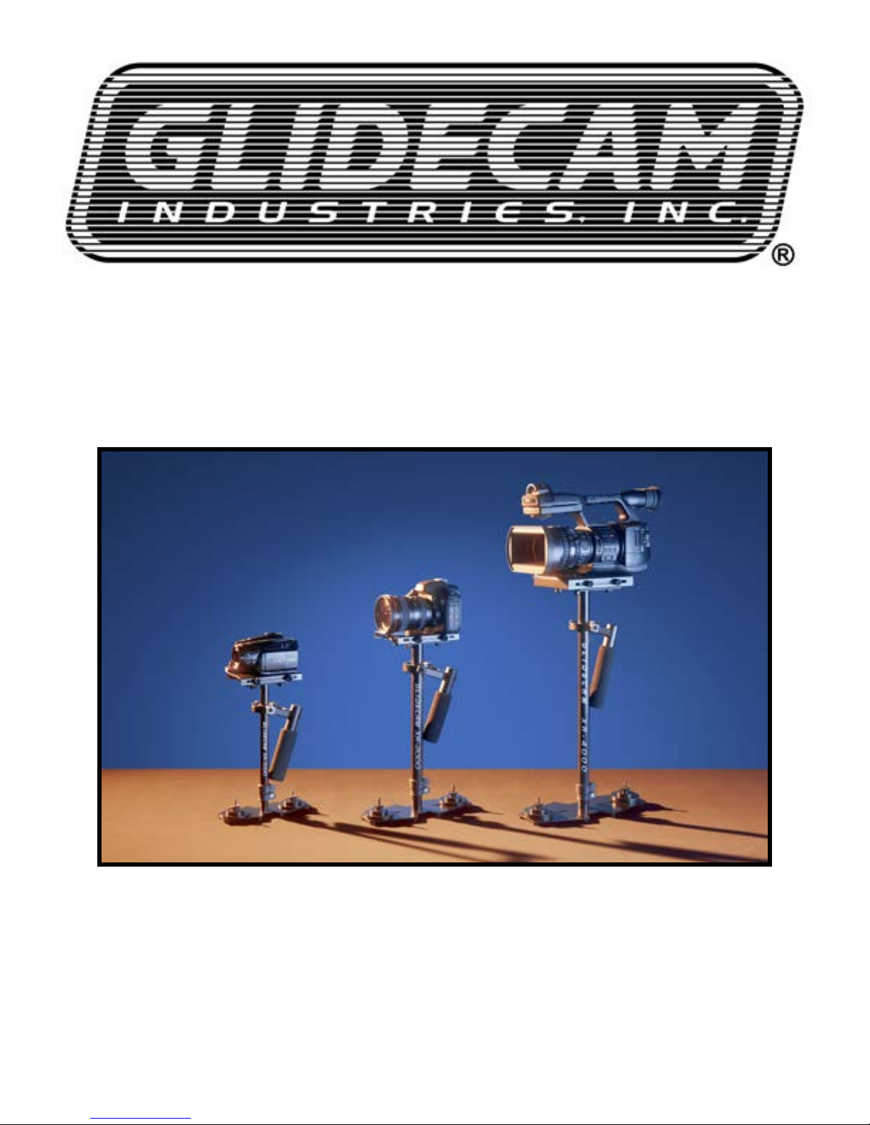
Congratulations on your purchase of a Glidecam XR-1000, XR-2000 or XR-4000.
The Glidecam XR-SERIES is a lightweight, aluminum, hand-held camcorder
stabilizing system designed to allow you to walk, run, go up and down stairs and travel
over rugged terrain without any camera instability or shake. When used correctly
the Glidecam XR-SERIES can move with such uidity and grace as to be virtually
indistinguishable from shots made by professional dollies, cranes and stabilizers.
The Glidecam XR-SERIES is the most versatile and dynamic of all the consumer
camcorder stabilizers on the market. It can shoot straight up and down, or even
sideways and still produce stable images.
Fluid tilts and pans, crane-like booms, dolly-type maneuvers, and the ability to shoot
smooth shots from moving vehicles are all easily accomplished with the Glidecam
XR-SERIES. The offset gimbaled handle-grip and enclosed bearing assembly allow
your hand to move freely in several directions, while the horizontal yoke allows your
hand and arm to move up and down, alleviating the bouncing, pogo-type action
often associated with our competitors’ systems. The upper camera platform moves
back and forth, and side to side to quickly allow the balancing of your camera in
relationship to the counterweights. By varying the amount of counterweight disks on
the base platform, the Glidecam XR-SERIES can support any camcorder weighing
up to 3 pounds (XR-1000) six pounds (XR-2000) and 4 to 10 pound (XR- 4000).
While the Glidecam XR-SERIES is in essence a very simple device, its simplicity
doesn’t lend ease in answering that often asked question, “how does it work?” To
answer this question completely would require delving into Newtonian Physics. We
would have to explain - center of gravity displacement, inertia, friction and angular
motion reduction etc. However, a quick answer reveals the Glidecam XRSERIES
works by isolating your hand and arm’s motions from your camera, while your camera
is balanced in a relatively motionless state.
The Glidecam XR-SERIES requires practice and understanding to achieve
professional looking results. We highly recommend that the user read this manual
thoroughly before setting up and operating the Glidecam XR-SERIES. Doing so
will save you time, and will minimize the risk of damage to your camcorder or the
Glidecam XR-SERIES. It is important to perform and follow the Set-up and Operation’s
procedures in the proper sequence, so as to avoid both frustration and a possible
accident.
If you have need of any technical assistance, you can call our Technical Support
Line at 1-781-585-7900, Monday through Friday between the hours of 9:00 am and
5:00 pm, Eastern Time.
We’re sure that once you have your Glidecam XR-SERIES up and running, you will
nd years of enjoyment with it.
#1 INTRODUCTION
2 3
TABLE OF CONTENTS
SECTION # PAGE #
1.
Introduction
3
2.
Glidecam XR-Series Parts And Components
4
3.
Assembling Your Glidecam XR-Series 8
4.
Attaching Your Camera To Your Glidecam XR-Series 15
5.
Balancing Your Glidecam XR-Series 18
6.
Handling Your Glidecam XR-Series 23
7.
Operating Your Glidecam XR-Series 24
8.
Shooting Tips 26
9.
Improper Techniques 27
10.
Other Camera Attachment Methods 28
11.
Professional Usage
28
12.
Maintenance
28
13.
Warning
29
14.
Warranty
29
15.
Online Information
30
4 5
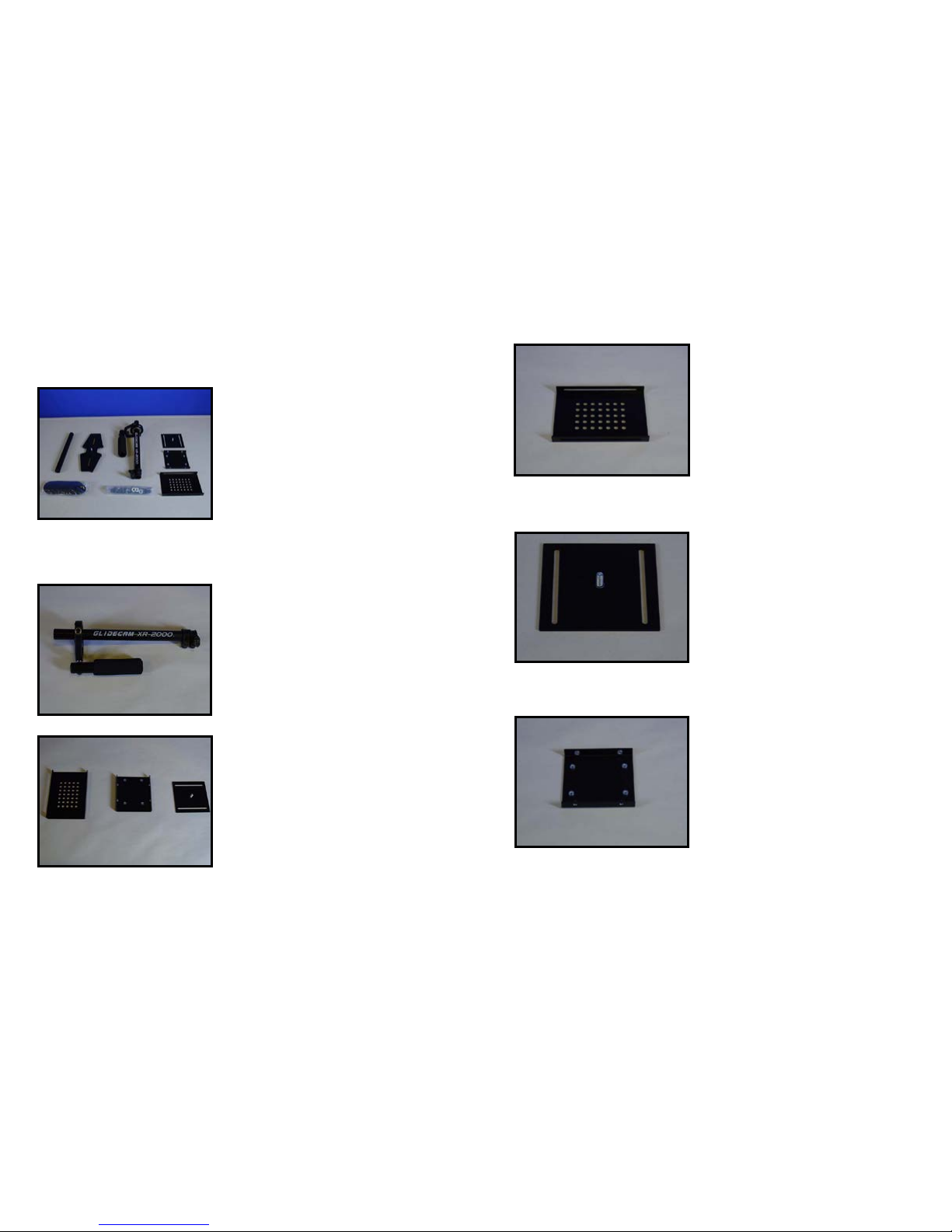
Figure 1
When you unpack your Glidecam XR-SERIES you
will see that it is not completely assembled.
Contents of the Glidecam XR-SERIES shipping box
include;
OPERATION MANUAL
XR-SERIES CENTRAL POST
HEAD PLATE
MID PLATE
BOTTOM PLATE
BASE PLATFORM
TELESCOPING POST
HARDWARE BAG
COUNTER WEIGHT DISCS
TOOLS NEEDED:You will need a Standard and
Phillips Head Screwdrivers. (not included)
#2 GLIDECAM XR-SERIES PARTS AND
COMPONENTS
NOTE: The TELESCOPING POST comes
inserted into the CENTRAL POST when
shipped.
Figure 2
This is the Glidecam XR-SERIES CENTRAL POST
with attached gimbal assembly.
Warning – Do not tighten the factory settings on
the gimbal, handle, and yoke. The yoke and handle
should remain loose just as it is shipped to you.
Figure 3
These are the pieces that makeup the head assembly
of the XR-SERIES.
1) HEAD PLATE (shown left)
2) MID PLATE (shown center)
3) BOTTOM PLATE(shown right)
Figure 4
This is the HEAD PLATE. This is the plate that you’ll
be mounting your camera on.
NOTE: The HEAD PLATE for the Glidecam XR-4000 is different
than the one shown to the left. The XR-4000 HEAD PLATE has
3/8” and 1/4” mounting holes.
Figure 5
This is the MID PLATE.
Figure 6
This is the BOTTOM PLATE.
6
Figure 7
This is the BASE PLATFORM.
NOTE: The Glidecam XR-1000 has a smaller BASE PLATFORM
and the XR-4000 has a larger BASE PLATFORM.
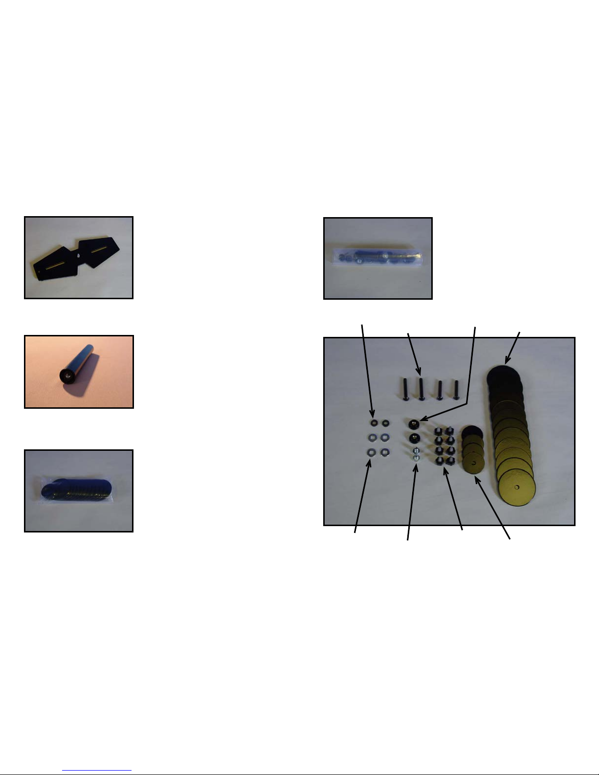
Figure 8
This is the TELESCOPING POST.
NOTE: The Glidecam XR-1000 and XR-4000 have
slightly different sizes.
Figure 9
These are the 12 COUNTER WEIGHT DISKS & 4
SMALL COUNTER WEIGHT DISKS. (shown in bag)
NOTE: The Glidecam XR-1000 has 8 LARGE COUNTER
WEIGHT DISKS.
Figure 10
This is the HARDWARE set. (shown in bag)
NOTE: The Glidecam XR-1000 and XR-4000 has slightly
different HARDWARE. The XR-4000 has 2 3/8” CAMERA
MOUNTING SCREWS & WASHERS.
2 Rubber Washers
Bolts for Counter Weight Disks
Black umb Nuts
1 3/4”
1 1/2”
4 1/2” Washers
2 Camera Mounting Screws
12 Counter Weight Disks
8 Black umb Screws
4 Small Counter Weights
Figure 11
7

Figure 12
First, Get the BASE PLATFORM and the
TELESCOPING POST.
See Figures 7 and 12 for BASE PLATFORM &
Figures 8 and 13 for TELESCOPING POST.
#3 ASSEMBLING YOUR GLIDECAM
XR-SERIES
Figure 13
Note the threaded insert located in the bottom the of
TELESCOPING POST.
8 9
Note the threaded insert located in the bottom the of
TELESCOPING POST.
Figure 14
Figure 15
At this point your Glidecam XR-SERIES should look
like Figure 15 which is with the TELESCOPING
POST attached to the BASE PLATFORM.
Figure 16
Now nd a pair of bolts (example: ¼” x 20 x 1.5”) and
attach RUBBER WASHERS as shown in the photo
to the left. Other length bolts for more COUNTER
WEIGHT DISKS are available and can be used.
NOTE: Different length bolts are provided so you can use the
longer bolts for a taller stack of COUNTER WEIGHTS DISKS.
Figure 17
Now, insert the selected bolts (example ¼” x 20 x
1 1/2”) with RUBBER WASHERS bolts through the
slots in the BASE PLATFORM as shown in this
picture and repeat this procedure for the slot on the
other side of the BASE PLATFORM.
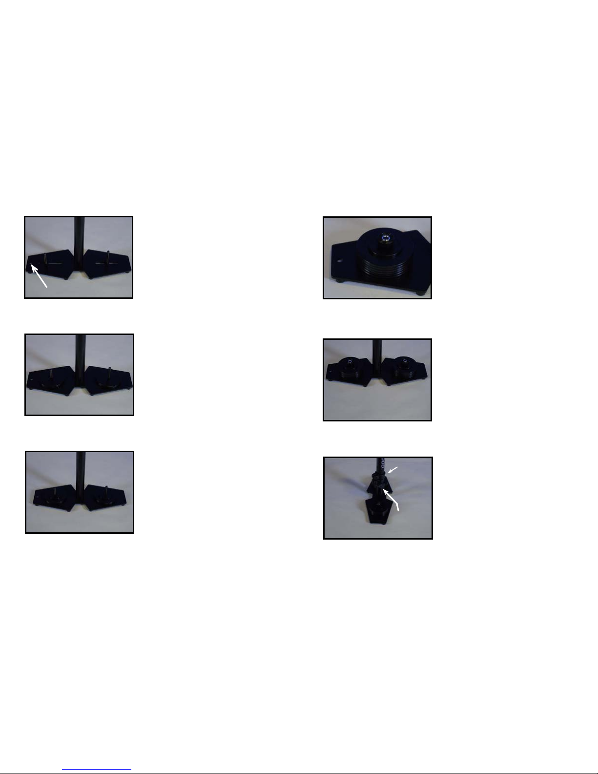
Figure 18
At this point your Glidecam XR-SERIES
should look like this photo.
NOTE: This is the Monitor Mounting Hole
Figure 19
Stack LARGE COUNTER WEIGHT DISKS and
center them over the bolts on the BASE PLATFORM
as shown in Figure 19.
NOTE: Different length bolts are provided so you can use the
longer bolts for a taller stack of COUNTER WEIGHTS DISKS.
NOTE: Heavy Cameras require more COUNTER WEIGHT
DISKS than light Cameras.
Figure 20
Place SMALL WEIGHT DISKS over COUNTER
WEIGHT DISK stacks.
10 11
Figure 21
Secure COUNTER WEIGHT DISKS with the BLACK
THUMB NUTS as shown in this photo and repeat this
procedure for the COUNTER WEIGHT DISKS on the
other side of the BASE PLATFORM.
Figure 22
Both COUNTER WEIGHT DISK stacks should now
be secured in place with the SMALL COUNTER
WEIGHT DISKS and BLACK THUMB NUTS as
shown in this photo.
Figure 23
Now, insert the TELESCOPING POST and attached
BASE PLATFORM up and into the XR-SERIES
CENTRAL POST.
The TELESCOPING CLAMP should be facing the
backend of the BASE PLATFORM, opposite the
monitor mounting hole, which is in the front of the
BASE PLATFORM.
Monitor Mounting Hole
should be in front.
Telescoping Clamp’s
“Adjustment Knob”
Shown aligned
Incorrectly.
Telescoping Clamp’s
“Adjustment Knob”
should be in back.
12
Figure 24
The TELESCOPING CLAMP may have to be re
aligned on the CENTRAL POST as the factory settings
may not be lined up. To realign the TELESCOPING
CLAMP use a hex key to loosen the clamp, realign
and then tighten.
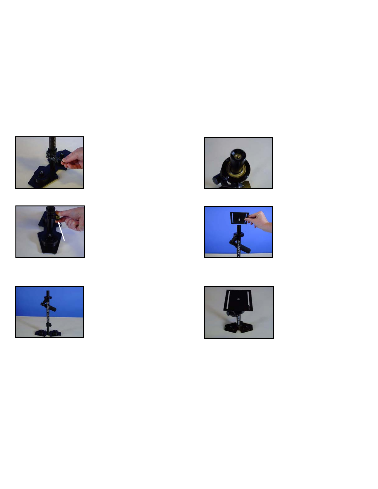
Figure 25
Securely tighten the “Adjustment Knob” on the
TELESCOPING CLAMP by rotating the Knob
clockwise as shown in Figure 25.
The “Adjustment Knob” should only be
hand tightened.
WARNING: DO NOT OVERTIGHTEN
THIS KNOB.
Telescoping Clamp’s
“Adjustment Knob”
Shown aligned
correctly.
Figure 26
At this point this is what your XR-SERIES should look
like Figure 26. Which is with the CENTRAL POST
with TELESCOPING POST, BASE PLATFORM, and
COUNTER WEIGHT DISCS.
13
Figure 27
This is a photo of the insert in the top of the CENTRAL
POST.
Figure 28
Rotate and screw the BOTTOM PLATE into the insert
in the top of the CENTRAL POST.
Figure 29
Tighten the BOTTOM PLATE to the top of CENTRAL
POST to ensure a tight t.

1514
Figure 30
Now place the MID PLATE on top of the BOTTOM
PLATE.
Figure 31
Insert the BLACK THUMB SCREWS through the
slots in the BOTTOM PLATE and into the threaded
inserts in the bottom of the MID PLATE.
Figure 32
At this point you should have four BLACK THUMB
SCREWS securing the MID PLATE to the BOTTOM
PLATE.
In the next section (section #3) you’ll be attaching
your HEAD PLATE and attached camera to the MID
PLATE.
#4 ATTACHING YOUR CAMERA TO THE
GLIDECAM XR-SERIES
Figure 33
***PLEASE NOTE*** These photographs show the
Glidecam 2000 PRO for illustrative purposes.
Now it’s time to attach your camera to the Glidecam
XR-SERIES.
Roll camera on pen to nd the center
of gravity, if needed.
Figure 34
First, nd the threaded insert on the bottom of your
camera.
THREADED INSERT
Figure 35
Remove the HEAD PLATE from the Glidecam XRSERIES and with the camera placed upside down
in your lap align the appropriate hole in the HEAD
PLATE with the threaded insert in the bottom of the
camera.
As shown in Figure 36.

16
Figure 36
The HEAD PLATE should be in alignment and square
with the bottom of the your camera.
Rubber or tape can be used as a gasket if needed.
Also, the Manfrotto 394, 3273, or 577 quick release
plates can be used. The Manfrotto 3273 and 577 are
good for longer cameras.
Figure 37
Find a CAMERA MOUNTING SCREW (see Figure
11) and ¼” washer and use these to attach the HEAD
PLATE to your camera.
Figure 38
Place your camera upside in your lap and with the
HEAD PLATE in place use a at head screwdriver to
secure the HEAD PLATE to your camera using the
CAMERA MOUNTING SCREW you’ve just selected.
17
Figure 39
The HEAD PLATE should be secured and square
with the camera.
NOTE: If you have a Video Camcorder or Film Camera that is
larger than the one used in this Manual, then you might wish to
rst nd the true front to back center of gravity of your Camera
by rolling the base of your Camera on a pen, then mark this
point on your Camera’s side with small piece of tape or a grease
pencil, and then use this marking to center the HEAD PLATE
over your Camera’s center of gravity.
Figure 40
Now connect your camera and the attached HEAD
PLATE to the MID PLATE.
Figure 41
Insert the remaining four BLACK THUMB SCREWS
through the slots in the sides of the HEAD PLATE
and into the inserts in the MID PLATE.

18
#5 BALANCING YOUR GLIDECAM XR-SERIES
Figure 42
Before you begin the balancing process check for
the following:
1) Camera is securely attached to HEAD PLATE.
2) Lens cap has been removed.
3) Camera battery is connected.
4) Flip out LCD is in it’s operating position.
(if applicable)
5) Telescoping clamp has been tightened.
6) All 8 BLACK THUMB SCREWS in place and
secure.
Figure 43
BALANCING THE HORIZTONAL AXIS
Now that your Glidecam XR-SERIES is assembled
properly, and your camera is securely attached to
the HEAD PLATE, you can now test the horizontal
balance.
The objective in obtaining correct horizontal balance
for the XR-SERIES is to allow the camera to remain
level during operation, given you are not applying
either a pan, tilt, or roll type of hand pressure to the
XR-SERIES. In other words, if the XR-SERIES is
horizontally balanced correctly, then the camera will
remain level, and the CENTRAL POST will remain
vertical unless you intentionally position the XRSERIES otherwise.
If the XR-SERIES is horizontally balanced correctly
it will always return to a level and vertical position
after you release any pan, tilt, or roll pressure on the
CENTRAL POST.
Figure 44
The best way of adjusting the horizontal balance is
to move the center of gravity of the camera. This can
be accomplished by either repositioning the camera
on the HEAD PLATE, or by adjusting the position of
the HEAD PLATE, either front to back or side to side
with the camera on it.
When checking the horizontal balance you want to
make sure that you’re picking up the XR-SERIES
from a at and level surface (i.e. a table) and that
you let the XR-SERIES hang freely as you hold
it. If the XR-SERIES is balanced correctly on its
horizontal axis, then it will be level and upright, with
the CENTRAL POST in a virtually perfect vertical
position, as pictured in Figure 43.
If the XR-SERIES tilts to the front (see Figure 44), then you will have to loosen up the BLACK
THUMB SCREWS on the sides of the HEAD PLATE and gently slide the HEAD PLATE back a
bit. If the XR-SERIES still tilts to the front, then move the HEAD PLATE more to the back.
If the XR-SERIES is tilting to the back, then move the HEAD PLATE to the front. Always secure
the BLACK THUMB SCREWS after any adjustments.
If you cannot get the front to back axis balanced with this method then try remounting your
camera to a different hole in the HEAD PLATE. Once you achieve correct horizontal balance for
the front to back axis, you can tighten the BLACK THUMB SCREWS that control the movement
of the HEAD PLATE.
19
2120
Figure 45
If the XR-SERIES leans to the right, then you will have to loosen
up the BLACK THUMB SCREWS on the bottom of the BOTTOM
PLATE and gently slide the MID PLATE over to the left a bit. If the
XR-SERIES leans to the left, then move the MID PLATE to the right.
Always secure and rmly tighten the BLACK THUMB SCREWS after
any adjustment.
After adjusting the side to side balance as mentioned above you
might have to go back and readjust the front to back balance to
obtain a ne balance of the whole system. You can use your eyes to
judge for correct horizontal balance, or you can use a bubble level
to ensure that the XR-SERIES has correct horizontal balance. The
Horizontal Balance of the XR-SERIES becomes less sensitive, as
the XR-SERIES becomes increasingly bottom heavy and conversely,
the horizontal balance becomes very sensitive, as the XR-SERIES
progresses towards correct vertical balance.
Also, another way of ne tuning the horizontal balance is to move
the COUNTER WEIGHT DISKS back and forth, or side to side on
the BASE PLATFORM. There are slots on the BASE PLATFORM to
help with this task. Also, replacing the WEIGHT DISKS away from
the CENTER POST on the BASE PLATFORM will increase panning
stability. Make sure to tighten the WEIGHTS down after you move
them.
NOTE: The Horizontal Balance of the XR-SERIES becomes less
sensitive as the XR-SERIES becomes increasingly bottom heavy,
and conversely, the horizontal balance becomes very sensitive, as
the XR-SERIES progresses towards correct vertical balance (see
next section).
Figure 46
Figure 47
NOTE: LATER, AFTER YOU ADJUST THE VERTICAL
BALANCE OF THE XR-SERIES, YOU WILL HAVE TO GO
BACK AND READJUST THE HORIZONTAL BALANCE AGAIN
IN ORDER TO OBTAIN A FINE BALANCE OF THE WHOLE
SYSTEM.
BALANCING THE VERTICAL AXIS
Now that your XR-SERIES is horizontally balanced,
it’s vertical axis can now be tested and properly
balanced. The objective in obtaining correct vertical
balance of the XR-SERIES is to allow the camera
and XR-SERIES to remain level during operation,
given you are not applying either a pan, tilt, or roll
type of hand pressure to the XR-SERIES, and most
importantly that the XR-SERIES’s CENTRAL POST
remains vertical even if you are walking, running,
or turning while the XR-SERIES is in operation. In
other words, if the XR-SERIES is vertically balanced
correctly, then the camera will remain level, and the
CENTRAL POST will remain vertical unless you
intentionally position the XR-SERIES otherwise. If
the XR-SERIES is not vertically balanced properly,
then it will swing about and pendulum when you
walk, run or turn.
If the vertical balance is set correctly you will be
able to move about quickly, as well as start or stop
moving suddenly, and still have the central support
post remain vertical. The best way to adjust the
XR-SERIES’s vertical balance is to telescope the
BASE PLATFORM in or out. Another way to adjust
the XR-SERIES vertical balance is to either add, or
subtract COUNTER WEIGHT DISCS from the BASE
PLATFORM.
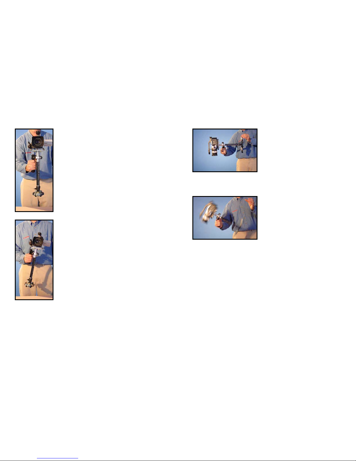
Figure 48
Figure 48 shows the Glidecam XR-SERIES
swinging between horizontal and vertical during
the “Sled Arc Test”. (see next page)

Figure 49
To test the balance of the vertical axis, perform what
is called the SLED ARC TEST. To perform the “Sled
Art Test” simply hold the XR-SERIES by it’s handle
and grab hold of the back end of the XR-SERIES
BASE PLATFORM and pull the base up and back
until the XR-SERIES CENTRAL POST is horizontal
(see Figure 47). Now carefully let go of the BASE
PLATFORM and count how many seconds it takes
for the XR-SERIES to then rst swing to vertical (see
Figures 48 and 49).
If the XR-SERIES is properly vertically balanced
then it should take about TWO to THREE seconds
for this to happen. Count your seconds with the
words “ one thousand one, one thousand two” etc for
accuracy. Adjust the amount of COUNTER WEIGHT
DISCS used or the length of the telescoping BASE
PLATFORM until it takes only TWO to THREE
seconds for the XR-SERIES CENTRAL POST to
swing in an arc from horizontal to vertical.
NOTE: The sled arc test “drop time” is operator preference.
The XR-SERIES will pendulum past vertical when the
sled arc test is performed, and one should count only the
time it takes to go from horizontal until it passes vertical
once. Swinging time not counted.
Another way to check for correct vertical balance
is to walk briskly forward with the XR-SERIES, and
then stop suddenly. If the XR-SERIES swings or
pendulums away from the upright vertical position
it was just in at the moment you stopped, then the
XR-SERIES is not balanced correctly. This type of
“movement test” applies also to running, or turning
around quickly with the XR-SERIES. Again, if the
XR-SERIES is balanced properly, then any body
movement like running or turning will not effect the
basic upright and vertical position of the XR-SERIES.
This photo shows the Glidecam XR-SERIES
swinging past an illustrated vertical line. The XRSERIES will pendulum or swing past this line
during the “Sled Arc Test”, and the XR-SERIES
will swing back and forth over a dozen times if left
to keep swinging, but it is only the time the XR-
SERIES rst swings in an arc from horizontal to
vertical that you need to analyze. After you have
counted the time it takes for it to go from horizontal
until it passes vertical once, then simply stop the
XR-SERIES from swinging, then either put the XR-
SERIES down or make adjustments and do the
test again.
22 23
#6 HANDLING YOUR GLIDECAM XR-SERIES
Figure 50
When handling your Glidecam XR-SERIES you will
be using one hand to hold onto the handle and the
other hand to gently guide the camera in the direction
you wish to shoot. We shall call the hand that holds
the handle, the holding hand (see Figure 50) and the
hand that aims the camera for tilting and panning etc,
the guiding hand.(see Figure 51)
When holding the handle of your Glidecam XR-
SERIES you will need to: 1) hold it rmly, and 2) hold
it either in the middle or at the bottom of the handle.
Which position you choose will depend on the kind of
shots you are shooting. For normal shooting hold the
handle in the middle. For shots that require aiming
the camera either up of down or sideways, hold the
handle rmly at the bottom. This will allow the yoke
to twist around without hitting your hand or knuckles.
When you handle your Glidecam XR-SERIES you
will want to use your guiding hand to gently hold
onto either, the point just below the yoke and bearing
assembly, (see Figure 51) or an area down by the
weight disks (see Figure 57) etc. These two areas
allow for easy control of the Glidecam XR-SERIES
when in use. Which position you choose will depend
on the kind of shots you are shooting.
Figure 51
For normal shooting hold the Glidecam XR-SERIES at the point just below the yoke and bearing
assembly. (see Figure 51) This will allow you to subtly aim the camera without disturbing the
camera’s upright position. It is this position which will allow you the smoothest shots, when walking
or running with the unit during normal shooting. NOTE: Make sure that your guiding hand and
holding hand do not touch either, the bearing assembly, or the yoke during shooting, for doing so
can cause unstable shooting. For unconventional shots, like one that require aiming the camera
either up or down, or sideways, hold the Glidecam XR-SERIES down or near the weight disks.
(Figure 57) This will allow your guiding hand to have a greater degree of control over the Glidecam
XR-SERIES while shooting very erratic shots.

#7 OPERATING YOUR GLIDECAM XR-SERIES
Figure 52
The Glidecam XR-SERIES is designed to work
correctly only when operated with two hands. (see
Figures 51 and 52) One being the holding hand and
the other being the guiding hand. If you try to operate
the unit with just your holding hand, the camera might
drift away from its originally balanced set-up position.
Also, without the guiding hand in place, you will be
unable to control the direction of the camera.
When operating the Glidecam XR-SERIES you will
not be able to put your eye right up to the eyecup
on the viewnder, for doing so will cause the unit to
be restricted in it’s ability to stabilize and eliminate
camera shake. Even though you cannot place your
eye directly up to the camera, you can however
indirectly look into the viewnder by removing it’s
magnifying eye cup and then watching the little
monitor that is inside the viewnder from several
inches away. Another choice in external viewing is
to simply rely on your own sight and judgment as to
what the camera is shooting. This is also referred to
as the point and shoot method. (This is very easy to
do if your camera is set-up with a Wide Angle Lens
Converter.)
Still another way to see what you are shooting is to
attach a Liquid Crystal Display, color video monitor
by Citizen TM or Sony TM to the accessory shoe on
top of your camcorder. We recommend using it or
a monitor similar to it, so you will achieve optimum
results with your Glidecam XR-SERIES.
Figure 53
Figure 54
24 25
Figure 55
You can also attach one of these L.C.D. monitors
directly to the BASE PLATFORM of the Glidecam
XR-SERIES. Located at the front edge of the BASE
PLATFORM is a 1/4” hole. If your camera has a ip
out LCD monitor (see Figure 42) then you will not
need an additional monitor.
Operating the Glidecam XR-SERIES for extended
periods of time can easily tire your holding hand. If
fatigue sets in while shooting, you can try operating
the Glidecam XR-SERIES with your other hand. You
can also rest for a while by placing the unit on the
ground, or by holding the unit with your guiding hand.
When handling and operating your Glidecam XRSERIES, always avoid violent moves. Doing so could
cause damage to the unit or cause your camera to
pull loose of the HEAD PLATE.
Glidecam Industries, Inc. also sells accessories for
the Glidecam XR-SERIES which can help you use
the XR-SERIES for extended periods of time. Call
us, or one of our authorized dealers, or go to www.
glidecam.com on the internet to nd out more. The
Glidecam BodyPod and the Glidecam Forearm
Brace make excellent support accessories for the
XR-SERIES.
The Glidecam XR-SERIES does not work under
water, nor is it waterproof (meaning the bearing and
of course your camera), so avoid direct exposure
to rain or water spray. Also the bearing is not sand
proof, so avoid getting dirt or sand into it. (see bearing
maintenance)
Figure 56
Figure 57

26 27
#8 SHOOTING TIPS
Figure 58
USE OF A WIDE ANGLE LENS CONVERTER
If you have a common consumer camcorder you will
probably discover that the widest setting on the lens
is not very wide. You might nd that this wide setting
is not adequate enough to give you the look like
those produced by professional Hollywood dollies,
cranes and stabilizers. To achieve this kind of look
you will have to place a wide angle lens converter on
the front of your existing camcorder lens. We highly
recommend that you use one on your camcorder
when shooting.
WALKING THE LINE
This is an exercise that is designed to help you
operater your XR-SERIES more successfully. Using
masking, camera, or gaffers tape create a cross
mark on a at and even wall (see Figure 58) This
cross mark will be used for framing purposes. Now,
on the oor leading up to the cross mark on the wall
tape a straight line, about 20 ft long. The idea behind
this exercise is to walk the line that you have taped
on the oor, while keeping the cross mark centered
in the viewing monitor of the camera that is attached
to the XR-SERIES (see Figure 59) In other words
this exercise helps you practice your framing with the
Glidecam XR-SERIES.
Figure 59
#9 IMPROPER TECHNIQUES
Figure 60
When shooting with the Glidecam XR-SERIES avoid
grabbing the CENTRAL POST. (see Figure 60) This
defeats the purpose, and isolation that the three axis
gimbal provides. Instead, handle your Glidecam XRSERIES as shown in Figure 51.
Figure 61
Also, allowing the handle of the Glidecam XR-SERIES
to come in contact with the BOTTOM PLATE (see
Figure 61) is something that you should avoid. This
limits your range of motion, and will result in “jerky”,
and unpleasant footage.
Instead, position the handle as shown in Figure 50.

#11 PROFESSIONAL USAGE
If you are using the Glidecam XR-SERIES to shoot professional looking shots, and you plan
on incorporating them into a short movie or some sort of commercial project, we suggest that
you preplan the shot out in advance, perhaps rehearse the move a few times before shooting,
and that you use an assistant to help you during complex shots. This will give you optimum
results and will make your movies look more professional.
Good luck with your shooting.
29
#13 WARNINGS
You should make sure that you are very careful when using the Glidecam XR-SERIES at
night or in low light conditions. Do not make the mistake of focusing so much on what you
are shooting that you trip or fall over something, or wander into something dangerous like a
swimming pool or automobile trafc, and be extra careful when shooting on stairs etc. These
cautions pertain to daytime shooting as well.
Storage - If you are going to store your Glidecam XR-SERIES for a long period of time then
please store the unit upright in a dry or low to normal humidity area whenever possible. If you
are unable to nd an environment like this, then we suggest you store the unit in an air tight
plastic container or bag. Standing the unit upright helps to alleviate stress on the system.
Cleaning - Do not use solvents or harsh cleaners of any kind on your Glidecam XR-SERIES.
If the unit becomes dirty, use only a cloth or sponge with water to gently rub the unit clean
28
#10 OTHER CAMERA ATTACHMENT
METHODS
Quick release and installation: To either remove or put your camera onto the CAMERA
MOUNTING PLATE without removing the MOUNTING PLATE from the top of the unit, loosen
the four BLACK THUMB SCREWS on the CAMERA MOUNTING PLATE and then slide the
PLATE either forwards or backwards, so as to gain access to the underside of the CAMERA
MOUNTING PLATE. (Not all of the MOUNTING HOLES are accessible this way, however all
the MOUNTING HOLES can be accessed by removing one set of left and right BLACK THUMB
SCREWS, and then sliding the CAMERA MOUNTING PLATE until all of the MOUNTING
HOLES are accessible.) Also, the Manfrotto 394, 3273 or 577 Quick Release plates work well.
Creating a gasket: If when attaching your camera to the HEAD PLATE you nd that the
bottom of your camera isn’t at enough to allow for a good solid attachment, try making and
adding a paper/cloth or rubber gasket to the HEAD PLATE. (Try using a piece of a rubber
dishwashing glove.) Simply cut the material to the size of the top of the HEAD PLATE and then
create a hole in it to allow the CAMERA MOUNTING BOLT to t through it, and into the base
of your Camcorder.
#12 MAINTENANCE
Bearing Maintenance: The main bearing on your Glidecam XR-SERIES is attached to the
Central Support Post about two inches down from the top. It is metal and is partially enclosed
by the Bearing Assembly. If after some period of time your bearing doesn’t turn smoothly, you
can oil it lightly. We recommend that you use very little oil. Very little, because this is all that
is needed, plus anything more than a little will end up coming out of the bearing and onto the
rest of your Glidecam XR-SERIES. Light oil may also be used (5-20 weight or 5-30 weight) if
needed on the yoke and handle bearings.
#14 WARRANTY
For 1 year from the date of shipment, we will repair or replace your Glidecam XR-SERIES, free
of charge, in the event of a defect in materials or workmanship (the shipment date appears on
your purchase receipt) which occurs during normal use in accordance with the Glidecam XRSERIES’s instruction manual. Shipping, packing, and insurance costs to and from the factory
are your responsibility. This limited warranty extends only to the original purchaser, and you
will need your purchase receipt. This warranty does not cover, by way of example, damage
caused by products not supplied by us or damage resulting from mishandling in transit,
accident, misuse, vandalism, neglect, modication, lack of reasonable care (or commercial
use, including rentals to others) of the Glidecam XR-SERIES or service by anyone other than
us. There are no express warranties except as listed above. This warranty gives you specic
legal rights and you may also have other rights which vary from state to state.
WE ARE NOT LIABLE FOR INCIDENTAL OR CONSEQUENTIAL DAMAGES RESULTING
FROM THE USE OF THE UNIT OR ARISING OUT OF ANY BREACH OF THIS WARRANTY.
ALL EXPRESS AND IMPLIED WARRANTIES, INCLUDING THE WARRANTIES OF
MERCHANTABILITY AND FITNESS FOR A PARTICULAR PURPOSE, ARE LIMITED TO
THE WARRANTY PERIOD.
To obtain service during (or after) the warranty period: Contact Glidecam Industries’ Customer
Service Department by calling 1-781-585-7900 or write to us at: 23 Joseph Street, Kingston,
MA 02364 and explain the problem.
DO NOT SEND THE UNIT TO US WITHOUT FIRST OBTAINING A RETURN
AUTHORIZATION NUMBER.

GLIDECAM INDUSTRIES, INC.
For more information
about
GLIDECAM
products and training please
visit
GLIDECAM
on the web.
www.Glidecam.com
or
Follow us on
Facebook.com/Glidecam Twitter.com/Glidecam Instagram.com/glidecam_
GLIDECAM INDUSTRIES, INC.
industries_inc
23 Joseph Street
Kingston, MA 02364
Phone: 1-781-585-7900
Phone: 1-800-600-2011
Fax: 1-781-585-7903
Website: www.Glidecam.com
 Loading...