


GLIDECAM
HD-SERIES
1000/2000/4000
Set-up and Operations Guide
Glidecam Industries, Inc. 23 Joseph Street, Kingston, MA 02364
Customer Service Line 1-781-585-7900
COPYRIGHT 2013 GLIDECAM INDUSTRIES, INC. ALL RIGHTS RESERVED
MANUAL
Manufactured in the U.S.A.

PLEASE NOTE
Since the Glidecam HD-2000 is essentially the same as the HD-1000 and the HD-4000, this
manual only shows photographs of the Glidecam HD-2000 being setup and used. The Glidecam
HD-1000 and the HD-4000 are just smaller and larger versions of the HD-2000. When there are
important differences between the HD-2000 and the HD-1000 or HD-4000 you will see it noted
with a ***. Also, the words HD-2000 will be used for the most part to include the HD-1000 and
HD-4000 as well.
2

TABLE OF CONTENTS
SECTION # PAGE #
1. Introduction 4
2. Glidecam HD-2000 Parts and Components 6
3. Assembling your Glidecam HD-2000 10
4. Attaching your camera to your Glidecam HD-series 18
5. Balancing your Glidecam HD-2000 21
6. Handling your Glidecam HD-2000 26
7. Operating your Glidecam HD-2000 27
8. Improper Techniques 29
9. Shooting Tips 30
10. Other Camera Attachment Methods 31
11. Professional Usage 31
12. Maintenance 31
13. Warning 32
14. Warranty 32
15. Online Information 33
3

#1 INTRODUCTION
Congratulations on your purchase of a Glidecam HD-1000 and/or Glidecam
HD-2000 or Glidecam HD-4000.
The amazingly advanced and totally re-engineered HD-Series from Glidecam
Industries represents the top of the line in hand-held camera stabilization.
The lightweight and state-of-the-art Glidecam HD-1000, HD-2000, and the HD-4000
hand-held camera stabilizers will transform your hard to watch shaky camera footage
into hypnotically smooth, professional footage.
The Glidecam HD-Series offers advanced features and a degree of sophistication
never before seen in a line of Hand-Held Camera Stabilizers.
With the Glidecam HD-Series Hand-Held Stabilizers your camcorder seems to
oat; always balanced and isolated from the undesirable motions of your hands.
Now you are free to move with your camera: panning, tilting, booming, and running
without any camera instability or shake.
The Glidecam HD-Series works so well that it allows you to shoot incredibly smooth
and graceful shots even while going to extremes like running up and down stairs or
traveling rugged terrain. When it comes to normal shooting, like walking or moving
the camera slowly around someone, the results are equally magical.
Each HD-Series Stabilizer’s offset, foam cushioned, handle grip is attached to a
free oating, three axis gimbal. This allows your hands to move up and down and
side-to-side, thereby isolating your hand’s unwanted motions from the camera. This
up and down movement alleviates the bouncing, pogo-type action often associated
with our competitor’s system. This is because their handle is not designed to have
the benecial ability to move up and down. This design feature, coupled with the over
all higher inertia of the HD-Series systems, produces a superior stabilization when
compared with our competition.
The unique and proprietary precision, three-axis gimbal incorporates several
adjustable axis convergence control. This allows all three axes to intersect for proper
operational alignment.
A camera-mounting platform with a quick-release, no-tools drop on camera plate
allows you to quickly attach or remove your camera. Ergonomic control knobs
allow quick, precise adjustments of the top stage’s back and forth and side-to-side
movement. These controls allow you to adjust the camera’s horizontal balance.
By varying the amount of counter weight on the base platform, or by changing the
length of the notool telescoping Central Post, you adjust the camera’s vertical balance.
When balanced properly the camera oats and you are ready to move into action.
4

The Glidecam HD-Series Stabilizers offer unparalleled controllability and ease of
use with their unique rigid, yet dynamically adjustable, control and weight distribution
surfaces. Setting up, controlling and adjusting the system’s balance is now quick and
precise.
A unique and proprietary dynamic base platform can expand or contract. This allows
you to easily adjust the system’s dynamic balance or to increase the system rotational
pan inertia.
Shot after shot and move after move, the Glidecam HD-Series Stabilizers deliver
beautifully smooth and professional results. With the Glidecam HD-Series you no
longer need a tripod or a dolly. All you need is your creativity, imagination, and
innovation.
Glidecam Industries is now becoming the choice of a generation. Glidecam makes
your decisions concerning stability and movement easy and simple. Simply rely
as so many have and still do, on using a Glidecam Camera Stabilizer. Glidecam
Industries, Inc., bringing two decades of Camera Stabilization with a wide range
of camera stabilizers, each optimized for various camera weights and shooting
conditions.
The Glidecam HD-Series requires practice and understanding to achieve professional
looking results. We highly recommend that the user read this manual thoroughly
before setting up and operating the HD-1000, HD-2000, or the HD-4000. Doing so
will save you time, and will minimize the risk of damage to your camcorder or the
Glidecam HD-1000, HD-2000, or HD-4000. It is important to perform and follow
the Set-up and Operation’s procedures in the proper sequence, so as to avoid both
frustration and possible accident.
If you have any needs for technical assistance, you can call our Technical Support
Line at 1-781-585-7900, Monday through Friday between the hours of 9:00am and
5:00pm Eastern Time.
We’re sure that once you have you Glidecam HD-1000, HD-2000, or HD-4000 up
and running, you will nd years of enjoyment with it.
5
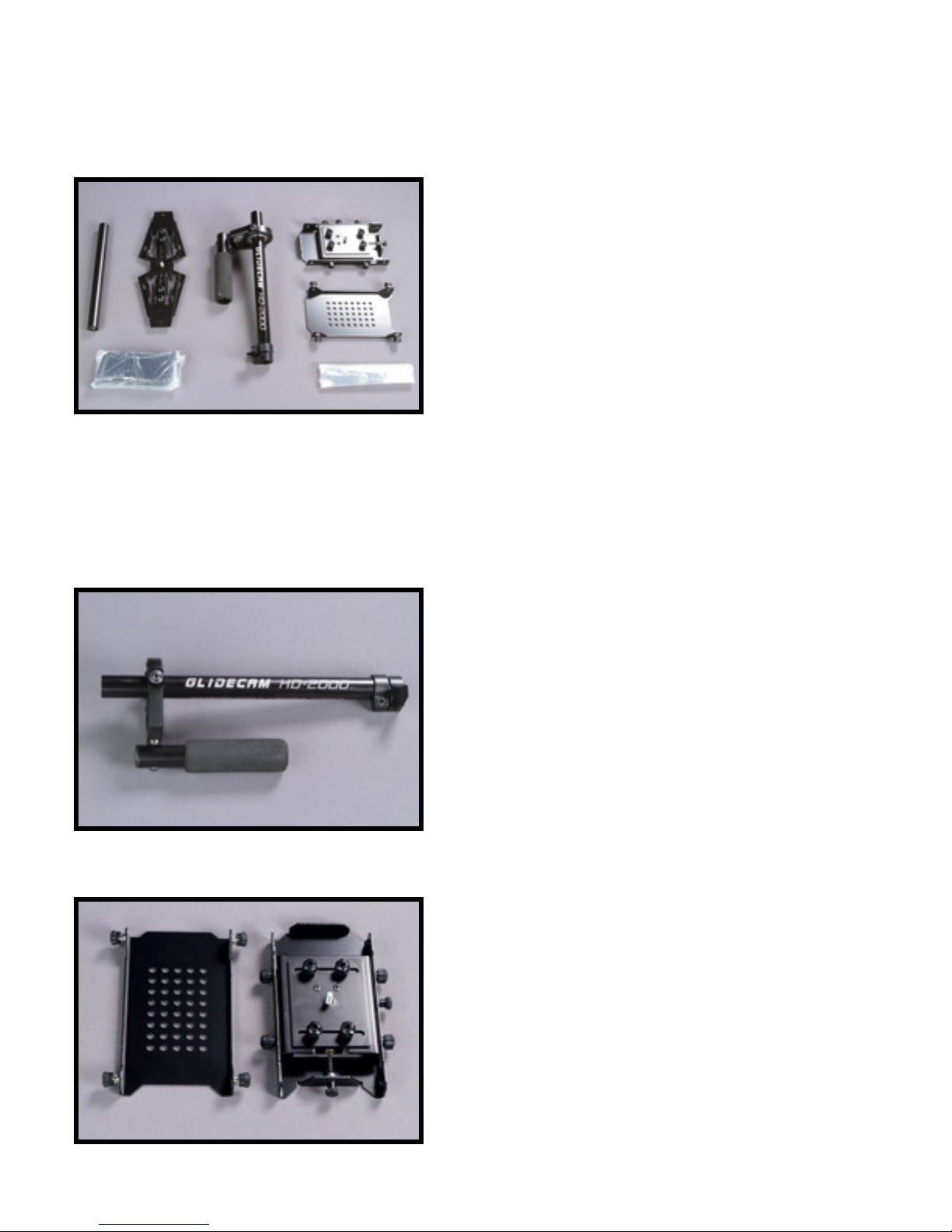
#2 GLIDECAM HD-2000 PARTS AND
COMPONENTS
When you unpack your Glidecam HD-2000 you will
see that some Assembly is required. The contents of
the Glidecam HD-2000 box includes the following:
(See Figure 1)
MANUAL
CENTER POST
QUICK RELEASE PLATE
CAMERA MOUNTING PLATFORM
EXPANDABLE BASE PLATFORM
TELESCOPING POST
HARDWARE BAG
Figure 1
COUNTER WEIGHTS
***NOTE: The TELESCOPING POST
comes inserted into the CENTRAL
POST when shipped.
Figure 2
TOOLS NEEDED:You will need a Standard and
Phillips Head Screwdrivers. (not included)
This is the Glidecam HD-2000 CENTRAL POST
with attached Gimbal assembly.
(See Figure 2)
***NOTE: The HD-1000 and the HD-4000 have
slightly different sizes.
WARNING: Do not adjust or tighten the factory
settings on the Gimbal, Handle, and Yoke. These
parts should remain loose and move freely, for
proper operation.
These are the pieces that makeup the HEAD
ASSEMBLY of the Glidecam HD-2000
Figure 3
1) QUICK RELEASE PLATE
2) CAMERA-MOUNTING PLATFORM
(See Figure 3)
6
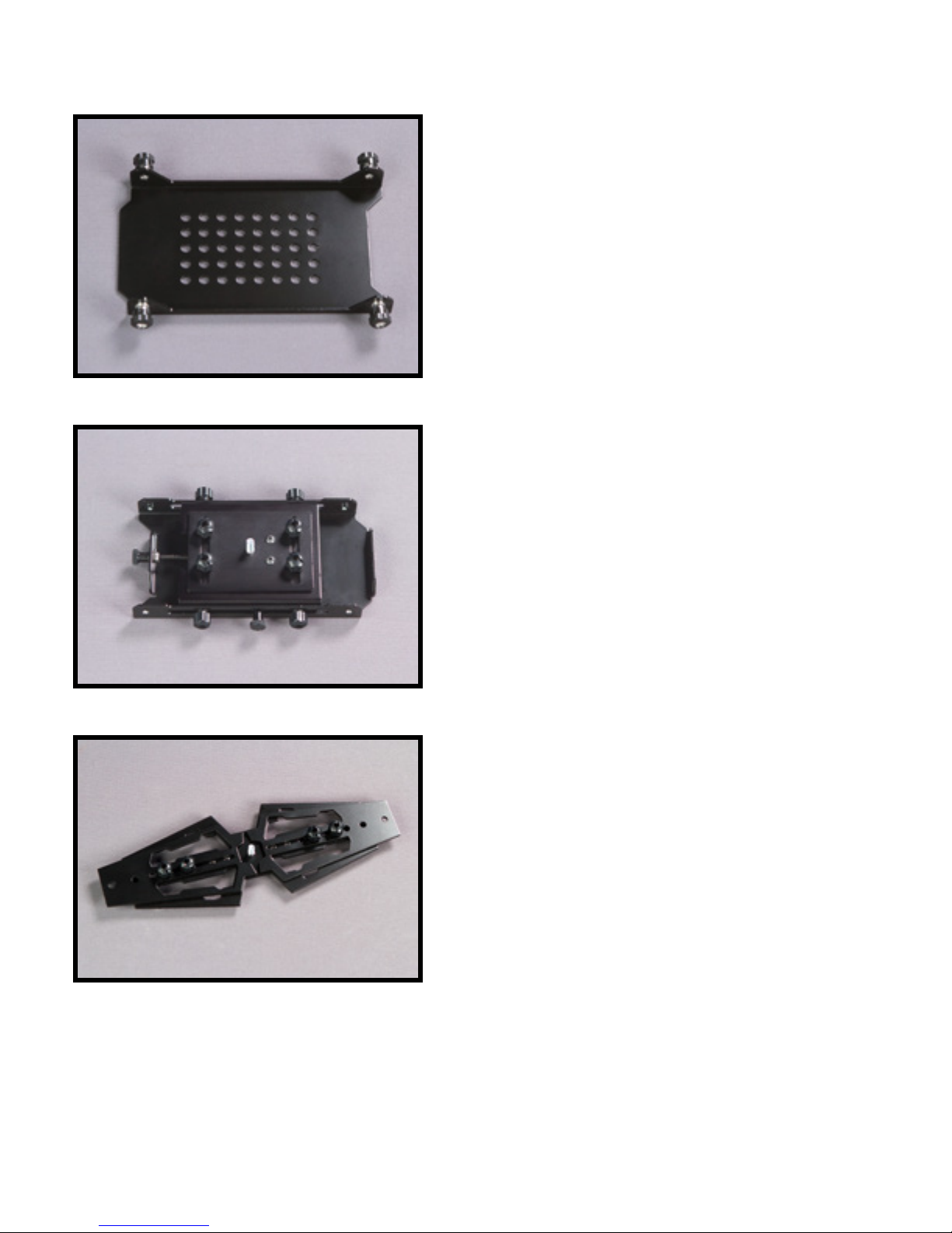
Figure 4
This is the QUICK RELEASE PLATE for the
Glidecam HD-2000 that you will attach to your
camera.
(See Figure 4)
(See SECTION 4 Attaching your Camera on PAGE
18 for Camera and QUICK RELEASE PLATE
Mounting)
***NOTE: The QUICK RELEASE PLATES for the
HD-1000 and the HD-4000 are different
This is the CAMERA-MOUNTING PLATFORM with
front-to-back and side-to-side movement
adjustment knobs.
Figure 5
Figure 6
This is the EXPANDABLE BASE PLATFORM.
(See Figure 6)
***NOTE: The HD-1000 and HD-4000 have slightly
different sizes.
7
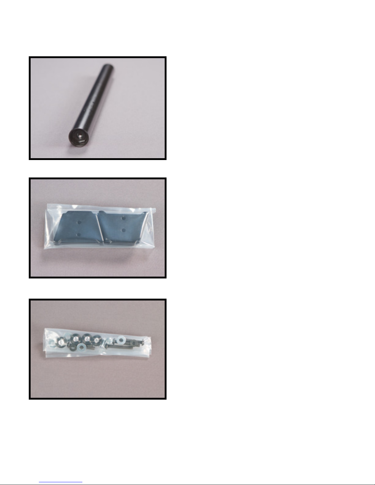
Figure 7
This is the TELESCOPING POST.
(See Figure 7)
***NOTE: The HD-1000 and HD-4000 have slightly
different sizes.
Shown in bag are the COUNTER WEIGHT
PLATES to be attached to the EXPANDABLE
BASE PLATFORM.
(See Figure 8)
***NOTE: The HD-1000 has 8 weight plates and
HD-2000 and HD-4000 have 12 weight plates.
Figure 8
Figure 9
Shown in the bag is the HARDWARE set for the
Glidecam HD-2000.
(See Figure 9)
***NOTE: The HD-1000 and the HD-4000 have
slightly different HARDWARE.
8
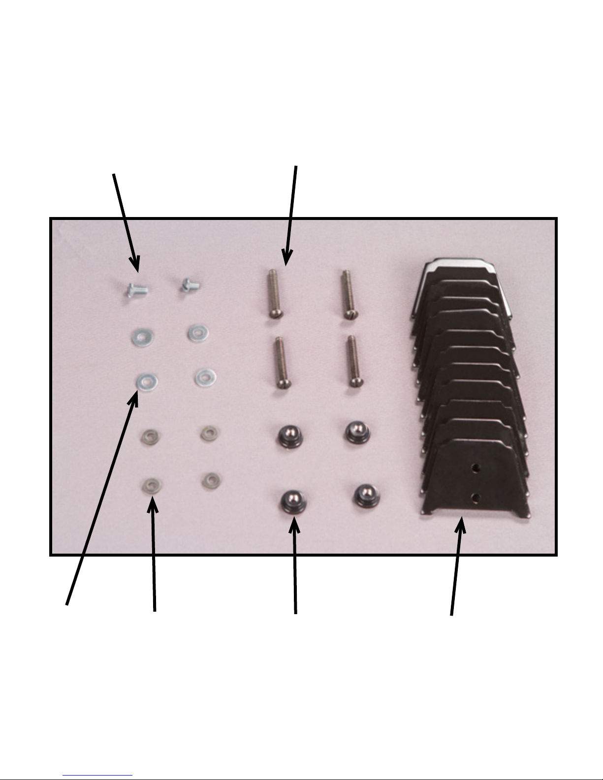
Camera Mounting Screws
Black Bolts for Counter Plates
1/4” Washers
Rubber Washers
Black umb Nuts
9
Counter Weight Plates
#3 ASSEMBLING YOUR GLIDECAM
HD-2000
First place the EXPANDABLE BASE PLATFORM
rmly on a leveled surface.
(See Figure 11)
Figure 11
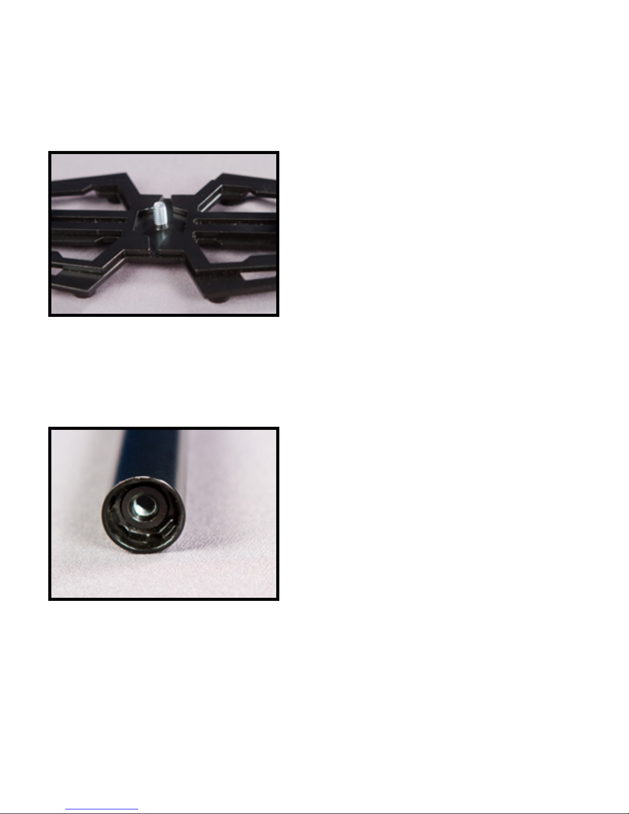
Figure 12
Next nd the TELESCOPING POST and locate
the THREADED INSERT which can be found in the
bottom of the TELESCOPING POST.
(See Figure 12)
10

Connect the TELESCOPING POST to the
EXPANDABLE BASE PLATFORM by tightly
screwing the TELESCOPING POST rmly on to
the EXPANDABLE BASE PLATFORM.
(See Figure 13)
NOTE: Over tightening may cause damage to
both the THREAD INSERT located in side the
TELESCOPING POST and the EXPANDABLE
BASE PLATFORM.
Figure 13
Figure 14
At this point the rst step of your Glidecam
HD-2000 assembly should be complete with the
TELESCOPING POST securely fastened to the
EXPANDABLE BASE PLATFORM.
(See Figure 14)
11

Figure 15
Now nd the four BLACK BOLTS and gently slip
the RUBBER WASHERS on to the bolts.
(See Figure 15)
NOTE: Repeat this step for all four BLACK BOLTS.
Now insert all four of the BLACK BOLTS with
RUBBER WASHERS into the four slots located on
either end of the EXPANDABLE BASE PLATFORM.
(See Figure 16)
Figure 16
Figure 17
At this point the second step of your Glidecam
HD-2000 assembly should be complete, with all four
BLACK BOLT and RUBBER WASHER
combination protruding threw the EXPANDABLE
BASE PLATFORM.
(See Figure 17)
12

Figure 18
Next, take the COUNTER WEIGHT PLATES and
slide them down on to the BLACK BOLTS until they
are resting on EXPANDABLE BASE PLATFORM.
(See Figure 18)
NOTE: The holes in the weights match the
placement of the bolts.
Secure the COUNTER WEIGHT PLATES by using
the BLACK THUMB NUTS to prevent weight
movement.
(See Figure 19)
Figure 19
Figure 20
Now, both COUNTER WEIGHT PLATE stacks
should now be secured to the EXPANDABLE BASE
PLATFORM with the BLACK THUMB NUTS.
(See Figure 20)
NOTE: Expanding the EXPANDABLE BASE
PLATFORM length and moving the COUNTER
WEIGHT PLATES apart will create a pan inertia
and this will slow down the rotation of the sled
and reduce the side-to-side movement while
moving.
13

Figure 21
Figure 22
Now, insert the TELESCOPING POST with the
EXPANDABLE BASE PLATFORM up in to the
CENTRAL POST.
(See Figure 21)
The TELESCOPING CLAMP ADJUSTMENT
KNOB should be aligned with the center of the
EXPANDABLE BASE PLATFORM. To align
the TELESCOPING CLAMP ADJUSTMENT
KNOB simply rotate the entire CENTRAL
POST into the correct position, and tighten the
ADJUSTMENT KNOB. Also leave about one
inch of the TELESCOPING POST showing
below the TELESCOPING CLAMP. Having the
TELESCOPING CLAMP ADJUSTMENT KNOB
aligned correctly, although not technically needed
to make your Glidecam HD-2000 function correctly,
does make it easier to reach the knob later when
you use it.
(See Figure 22)
Securely tighten the ADJUSTMENT KNOB on the
TELESCOPING CLAMP by rotating the knob
clockwise.
(See Figure 23)
NOTE: The ADJUSTMENT KNOB should only
be tightened by hand.
WARNING: Do not over tighten the
ADJUSTMENT KNOB as it could cause thread
stripping.
Figure 23
14

At this point your Glidecam HD-2000 should have
the CENTRAL POST and TELESCOPING
POST aligned correctly on the EXPANDABLE
BASE PLATFORM assembly.
(See Figure 24)
NOTE: The amount of COUNTER WEIGHTS will
vary depending on your Camera weight. Don’t
worry about this to much, for later you will set
the number of COUNTER WEIGHTS to the correct
amount required for you specic Camera.
Figure 24
Figure 25
Next, locate the THREADED INSERT which
can be found in the top of the CENTRAL POST.
(See Figure 25)
15

Figure 26
Rotate and screw the CAMERA MOUNTING
PLATFORM into the THREADED INSERT in the top
of the CENTRAL POST.
(See Figure 26)
There are two ways to create this correct alignment.
The rst and easiest is to loosen the ADJUSTMENT
KNOB on the TELESCOPING CLAMP and rotate
the parts until correctly aligned. Then simply retighten
the ADJUSTMENT KNOB.
(See Figure 27)
NOTE: Remember to leave at least one inch of
the TELESCOPING POST showing below the
TELESCOPING CLAMP.
Figure 27
16

Figure 28
The second method to correctly align the parts is to use an Allen Wrench or Screwdriver
to loosen the “Screw” on the top part (See Figure 27) of the TELESCOPING CLAMP until
you can rotate the parts so they are correctly aligned. Then simply retighten the screw.
(See Figure 28)
NOTE: the second method of alignment is better because it keeps the TELESCOPING
CLAMP ADJUSTMENT KNOB aligned correctly (See Figure 22). Having the
TELESCOPING CLAMP ADJUSTMENT KNOB aligned correctly, although not
technically needed to make your Glidecam HD-2000 function correctly does make it
easier to reach the TELESCOPING CLAMP ADJUSTMENT KNOB later when in use.
17

#4 ATTACH YOUR CAMERA TO THE
GLIDECAM HD-2000
Now it is time to attach your Camera to the Glidecam
HD-2000’s QUICK RELEASE PLATE.
(See Figure 29)
Figure 29
First nd the THREADED INSERT on the bottom of
your camera.
(See Figure 30)
Figure 30
Figure 31
THREADED INSERT
Now preferably sit down in a chair and place your
Camera (base side up) in your lap. Then place and
center the QUICK RELEASE PLATE on the back
side of your Camera.
(See Figure 31)
18
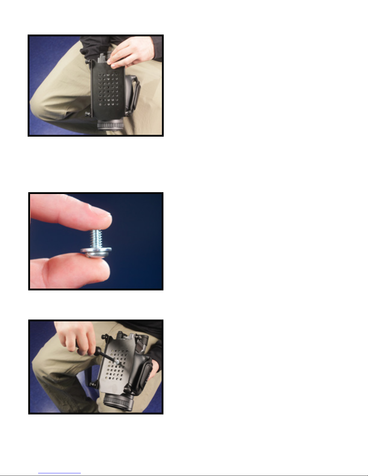
Figure 32
Make sure the QUICK RELEASE PLATE is in
alignment square with the bottom of your Camera and
make sure the THREADED INSERT on the base of
your Camera is aligned with one of the MOUNTING
HOLES in the QUICK RELEASE PLATES.
(See Figure 32)
NOTE: You have a Video Camcorder or Film
Camera that is larger than the one used in this
Manual, then you might wish to rst nd the true
front to back center of gravity of your Camera by
rolling the base of your Camera on a pen until it
is balanced upon the pen, and mark this point
on your Camera’s side with a small piece of tape
or a grease pencil, and then use this marking to
center the QUICK RELEASE PLATE over your
Camera’s center of gravity.
Now use a CAMERA MOUNTING SCREW and a
1/4” WASHER attach the QUICK RELEASE PLATE
to your Camera.
(See Figure 33)
Figure 33
Figure 34
***NOTE: If the shorter CAMERA MOUNTING
SCREW does not work then try the slightly larger
CAMERA MOUNTING SCREW. Also try using more
than one 1/4” WASHER or no 1/4 WASHERS at all
if you have trouble with the mounting procedure.
You can also use the same MOUNTING SCREWS
and WASHERS for the HD-1000 and the HD-4000.
With your Camera base side up in your lap and with
the QUICK RELEASE PLATE in place, use a at head
screwdriver to secure the QUICK RELEASE PLATE
to your Camera using the CAMERA MOUNTING
SCREW and 1/4” WASHER combo you have just
selected.
(See Figure 34)
WARNING: Do not over tighten this screw. Over
tightening could break the THREADED INSERT
on your Camera.
19

Figure 35
If all is correct, the QUICK RELEASE PLATE should
now be securely fastened to your Camera.
(See Figure 35)
NOTE: If you can easily rotate the QUICK
RELEASE PLATE on the base of your Camera,
even though you have adequately tightened the
CAMERA MOUNTING SCREW, and you do not feel
comfortable tightening the CAMERA MOUNTING
SCREW any more, then you should think about
using some sort of a exible GASKET between
your Camera base and QUICK RELEASE PLATE.
You could use rubber tape, or a square at piece
of rubber (for example, creating one by cutting
up an old rubber dish washing glove)
Now securely place and center your Camera and
the attached QUICK RELEASE PLATE on top of the
CAMERA MOUNTING PLATFORM.
(See Figure 36)
NOTE: Make sure the four knobs are pulled all
the way out before installing. Once the plate
is installed push the four knobs in and rotate
clockwise to securely tighten.
Figure 36
20
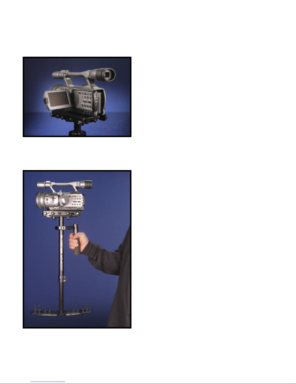
#5 BALANCING YOUR GLIDECAM HD-2000
** Figures 38-44 show a fully balanced Glidecam HD-2000 for illustrative purposes only. This may not be reective
of your individual Glidecam setup.
Before you begin the balancing process check the
following and make sure they have been done:
1. Camera is securely attached to the QUICK
RELEASE PLATE and the four knobs are
pushed in and tightened.
2. The Lens Cap has been removed.
3. Camera Battery and Recording Media are
installed.
4. Flip out LCD into it’s operating position.
(See Figure 37)
Figure 37
5. Telescoping clamp has been tightened and
weights have been added.
BALANCING THE HORIZONTAL AXIS
Now that your Glidecam HD-2000 is setup and
assembled properly, you can test and setup the
horizontal balance of the system. The objective in
achieving correct horizontal balance for the HD-
2000 is to allow the Camera to remain level during
operation, given that you are not applying either a
pan, tilt, or roll type hand pressure to the HD-2000. In
other words if the HD-2000 is horizontally balanced
correctly, then the Camera will remain level, and the
CENTRAL POST will remain vertical unless you
intentionally position the HD-2000 otherwise. Also,
if the HD-2000 is horizontally balanced correctly
it will always return to a level and vertical position
after you release any pan, tilt, or roll pressure on the
CENTRAL POST.
(See Figure 38)
Figure 38
21
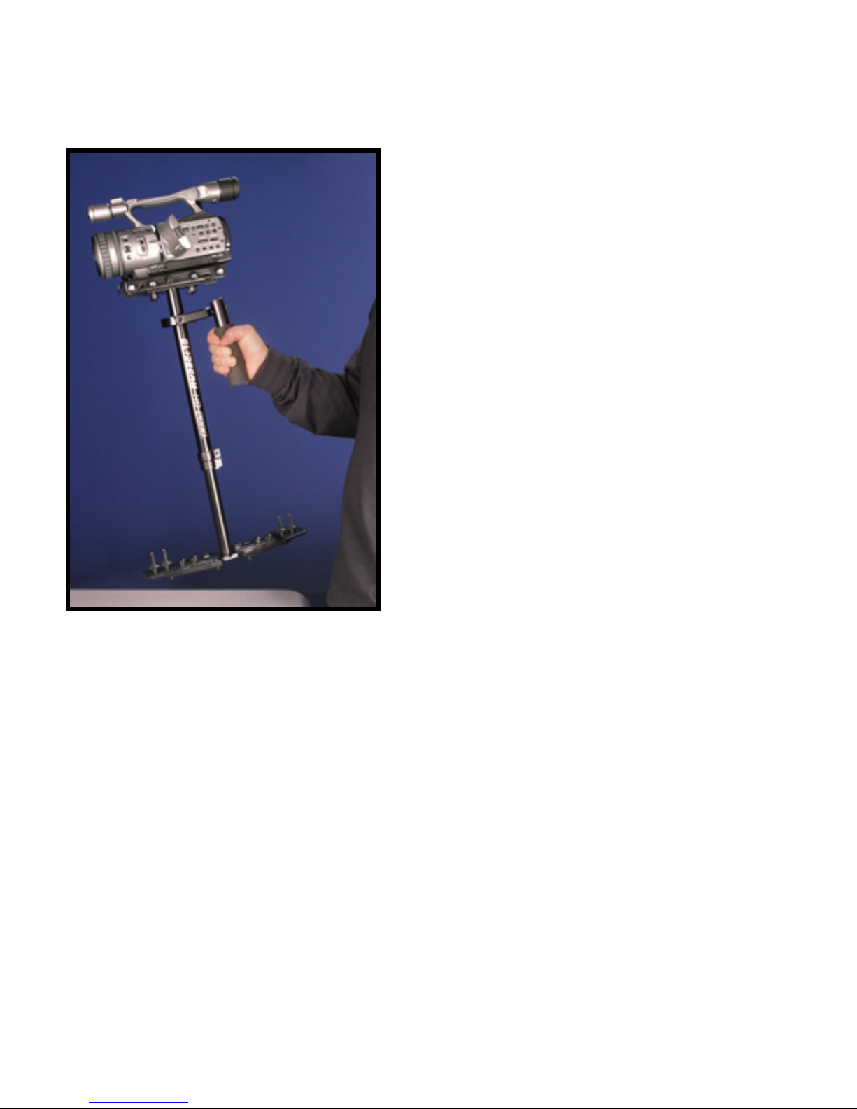
Figure 39
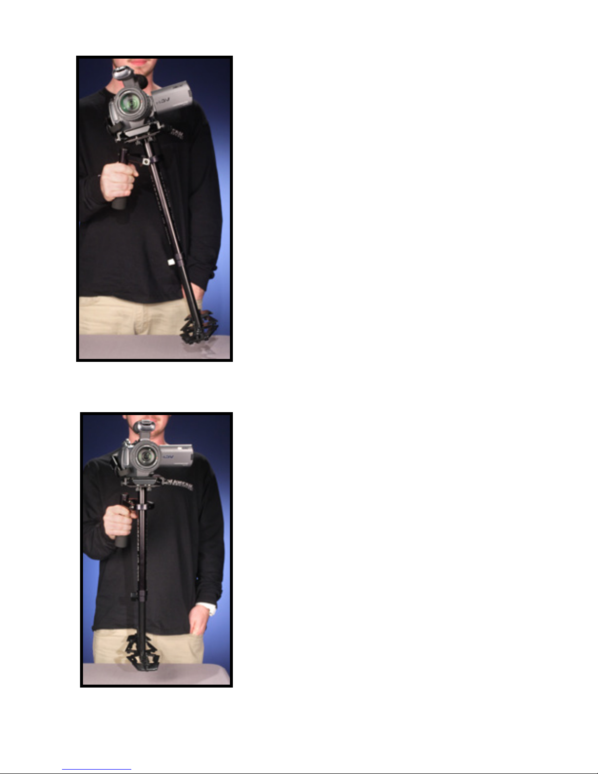
When testing for correct horizontal balance you need
to make sure that you pick up your HD-2000 from a
at surface (a table for example) and that you let the
HD-2000 hang freely as you hold it. (See Figure 38)
If the HD-2000 is balanced correctly on it’s horizontal
axis, then it will be level with the CENTRAL POST in
a virtually perfect vertical position.
(See Figure 38)
Most likely your HD-2000 will not be balanced (Figure
39) and so you will have to adjust it until it does.
WARNING: If you do not have enough COUNTER
WEIGHT on the BASE PLATFORM at this time, the
entire Glidecam will ip completely upside down.
If this happens add more COUNTER WEIGHT
below until during this test the Glidecam remains
right side up.
The best way of adjusting the horizontal
balance is to move the center of gravity of the
Camera. This can be accomplished by either
#1) re-bolting the Camera to a different area of the
QUICK RELEASE PLATE, or by #2) adjusting the
position of the QUICK RELEASE PLATE and CAMERA MOUNTING PLATE either front-to-back
or side-to-side with the Camera on it. Method #2 is the preferred method.
If the Glidecam HD-2000 tilts to the front (See Figure 39), then you will have to loosen the thumb
screws on the side of the CAMERA MOUNTING PLATE and turn the ADJUSTMENT KNOB
counter clockwise. If the Glidecam HD-2000 still tilts to the front, then move the QUICK RELEASE
PLATE more to the back by turning the adjustment knob. If the Glidecam HD-2000 is tilting to the
back, then move the QUICK RELEASE PLATE to the front by turning the ADJUSTMENT KNOB
clockwise. Always secure the thumb screw after any adjustments. If you cannot get the front to
back axis balanced with this method then try remounting your Camera to a different hole on the
QUICK RELEASE PLATE. Once you achieve balance for the front-to-back axis, tighten the four
thumbscrews on the CAMERA MOUNTING PLATFORM.
22
If the Glidecam HD-2000 leans to the right, then
you will have to loosen the THUMB SCREWS on the
bottom of the CAMERA MOUNTING PLATFORM
and then turn the side to side ADJUSTMENT KNOB
counterclockwise. If the Glidecam HD-2000 leans to
the left from the operator’s point of view (See Figure
40) then move it to the right by turning the side to side
ADJUSTMENT KNOB clockwise. Always secure
and rmly tighten the THUMB SCREWS after any
adjustment. The side to side horizontal axis is shown
correctly adjusted.
(See Figure 41)
After adjusting the side to side balance as mentioned
above you might have to go back and readjust the
front to back balance to obtain a truly ne balance of
the whole system. You can use your eyes to judge for
correct horizontal balance, or you can use a small and
lightweight bubble level (not included) to ensure the
Glidecam HD-2000 has correct horizontal balance.
Figure 40
***NOTE: The Horizontal Balance of the Glidecam
HD-2000 becomes less sensitive as the Glidecam
HD-2000 becomes increasingly bottom heavy,
and conversely, the horizontal balance becomes
very sensitive, as the HD-2000 progresses
towards correct vertical balance.
Figure 41
23
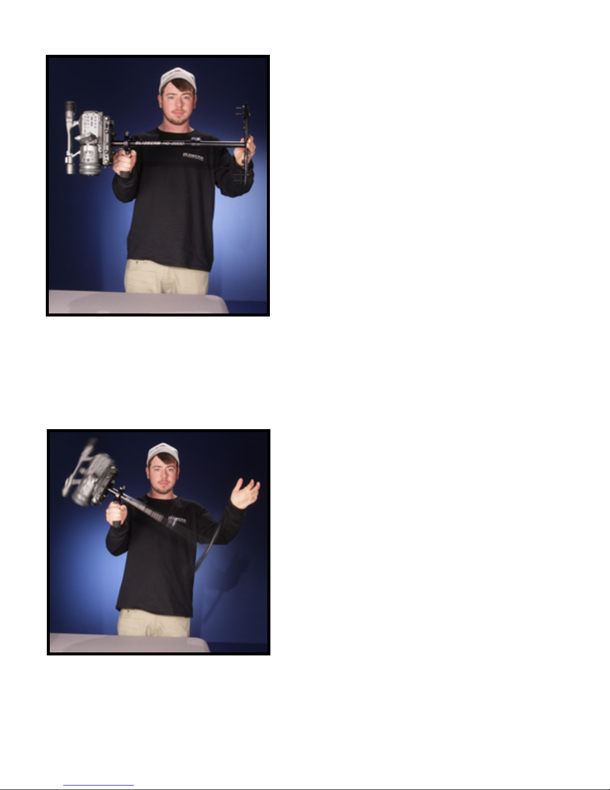
Figure 42
***NOTE: Later after you adjust the vertical
balance of the GLIDECAM HD-2000 you will have
to go back and readjust the horizontal balance
again in order to obtain a true ne balance of the
whole system.
BALANCING THE VERTICAL AXIS
Now that your Glidecam HD-2000 is horizontally
balanced, it’s vertical axis can now be tested and
properly balanced. The objective in obtaining correct
vertical balance of the HD-2000 is to allow the Camera
and HD-2000 to remain level during operation, given
you are not applying either a pan, tilt, or roll type of
hand pressure to the HD-2000, and most importantly
that the HD-2000’s CENTRAL POST remains vertical
even if you are walking, running, or turning while the
Glidecam HD-2000 is in operation. In other words,
if the HD-2000 is vertically balanced correctly then
the Camera will remain level, and the CENTRAL
POST will remain vertical unless you intentionally
position the HD-2000 otherwise. If the HD-2000 is
not vertically balanced properly, then it will swing
about and pendulum when you walk, run, or turn.
Figure 43
Again, if the vertical balance is set correctly you
will be able to move about quickly, as well as start or
stop moving suddenly, and still have the CENTRAL
POST remain vertical. To adjust the
Glidecam HD-2000’s vertical balance you can
either add, or subtract COUNTER WEIGHTS from
the BASE PLATFORM, or telescope the BASE
PLATFORM in or out. After you have
approximately the right amount of weight on the
base, you can then ne tune the VERTICAL
BALANCE by using the TELESCOPING POST.
24

Figure 44
This photo shows the Glidecam HD-2000
swinging past the illustrated vertical line. The
HD-2000 will pendulum or swing past this line
during the “SLED ARC TEST”, and the HD-2000
will swing back and forth over a dozen times if left
to swing, but it is only the time the HD-2000’s rst
swing in an arc from horizontal to vertical that you
need to analyze. After you have counted the times
it takes for it to go from Horizontal until it passes
vertical once, then simply stop the HD-2000 from
swinging, then either put the HD-2000 down or
make adjustments to perform the test again.
To test the balance of the vertical axis, perform what
is called the SLED ARC TEST. to perform the SLED
ARC TEST, simply hold the Glidecam HD-2000
by it’s handle and then grab a hold of the back end
of the HD-2000’s BASE PLATFORM, then pull the
BASE up and back until the HD-2000’s CENTRAL
POST is horizontal and motionless (See gure 42)
then gently let go of the BASE PLATFORM and
count how many seconds it takes for the HD-2000
to go from the horizontal position it was just in (See
Figure 43) to the moment it rst passes the vertical.
If the Glidecam HD-2000 is vertically balanced
properly, then it should take about TWO to THREE
seconds for this to happen. (this is called DROP
TIME) Count your seconds with the words “one
thousand one, one thousand two etc for accuracy.
Adjust the amount of COUNTER WEIGHTS used on
the BASE PLATFORM or adjust the length of the
TELESCOPING POST up or down, until it only takes
TWO to THREE seconds for the HD-2000 CENTRAL
POST to rst swing in an arc from horizontal to
vertical.
NOTE: The amount of DROP TIME nally set is
ultimately up to you to decide. Different DROP
TIMES change the vertical balance, and therefore
change the results obtainable when shooting.
***NOTE: Adding more weight or telescoping
out the base will speed up the DROP TIME.
Removing weight or telescoping the base in
will slow the DROP TIME.
position it was just in that moment you stopped, then you know the HD-2000 is not balanced
correctly. Adjust the amount of COUNTER WEIGHTS used on the BASE PLATFORM or adjust
the length of the TELESCOPING POST up or down until the HD-2000 remains vertical during the
“MOVEMENT TEST”.
This “MOVEMENT TEST” also applies to running or turning around quickly with the HD-2000.
Again if the HD-2000 is balanced properly, then any body movement like running or turning quickly
will not effect the basic upright, vertical position of the HD-2000
Another way to check for correct vertical balance,
known as the ”MOVEMENT TEST”, is to walk
forward with the Glidecam HD-2000 and then stop
suddenly. If the HD-2000 BASE PLATFORM swings
or pendulums away from you, or upright vertical
25

#6 HANDLING YOUR GLIDCAM HD-2000
Before you operate and lm with your Glidecam HD2000, you will need to know how to handle the equipment.
When handling your HD-2000 you will use one hand to
hold on to the handle and the other hand to gently guide
the camera in the direction you wish to shoot. We call the
hand that holds the handle, the “HOLDING HAND” and
the hand that aims the Camera for tilting and panning. the
“GUIDING HAND”.
When holding the handle of your Glidecam HD-2000 you
will need to: 1) hold it rmly, and 2) hold it either in the
middle or the bottom of the handle. Which position you
Figure 45
Figure 45 shows you the correct way to hold
the handle; however, remember that you should
always use both hands when using the HD-2000.
choose will depend on the kind of shot you are shooting.
For normal shooting hold the handle near the middle.
(See Figure 45) For shots that require aiming the Camera
either up or down or sideways, hold the handle rmly at the
bottom. This will allow the “YOKE” part of the GIMBAL to
twist around without hitting your hands or your knuckles.
When you handle your Glidecam HD-2000 you will want to
use your “GUIDING HAND” to gently hold onto either, the
point just below the “YOKE” and bearing assembly, (See
Figure 46) or and area down by the BASE PLATFORM.
(See Figure 53) These two areas allow for easy control of
the HD-2000 when in use. Which position you choose will
depend on the kind of shot you are shooting.
Figure 46
Figure 47
For normal shooting hold the Glidecam HD-2000 at the
point just below the “YOKE” and bearing assembly. (See
Figure 46) This will allow you to subtly aim the Camera
without disturbing the Camera’s upright position. It is this
position that will allow you the smoothest shots when
walking or running with the HD-2000 during normal
shooting.
NOTE: Make sure that your “GUIDING HAND” and
“HOLDING HAND” do not touch either the bearing
assembly or the “YOKE” during shooting, for
unconventional shots, like ones that require aiming
the Camera either straight up or down, or sideways,
hold onto the HD-2000 on the lower part of the post or
down near the weight. (See Figure 53) This will allow
your “GUIDING HAND” to have a greater degree of
control over the HD-2000 while shooting erratic shots
26

#7 OPERATING YOUR GLIDECAM HD-2000
The Glidecam HD-2000 is designed to work
correctly only when operated with two hands. (See
gure 46 and 48) If you try to operate the unit with
just your “HOLDING HAND”, the Camera will most
likely drift away from it’s original position. Without
your “GUIDING HAND” in place, you will be unable
to control the direction of the Camera
Figure 48
When Operating the Glidecam HD-2000 you will
not be able to put your eye right up to the eyecup
on the viewnder, for doing so will cause the unit to
be restricted in it’s ability to stabilize and eliminate
Camera shake. Even though you cannot place your
eye directly up to the Camera viewnder, you can
either use the Camera’s built-in LCD MONITOR or
attach an external LCD MONITOR (not included)
directly to the BASE PLATFORM of the HD-2000. A
1/4” Monitor “MOUNTING HOLE” is located at both
the front and back edges of the BASE PLATFORM.
(See Figure 47)
Figure 49
Figure 50
You can also attach an external LCD MONITOR to
the accessory shoe on the top of your Camcorder.
We believe that better results are obtained when
you attach the Monitor to the HD-2000’s base, (See
Figure 47) because this way you generally have to
look slightly down to see the Monitor. In doing so,
your feet are more visible to your peripheral vision.
This makes negotiating obstacles with the HD-2000
safer.
27

Figure 51
NOTE: Figures 51 through 53 show the Glidecam
HD-2000 being used in different ways.
Operating your Glidecam HD-2000 for extended
periods of time can easily tire your “HOLDING
HAND”. If fatigue sets in while shooting you can try
operating the Glidecam HD-2000 with you other
hand. You can also rest for a while by placing the unit
upright on a level surface, docking the sled if using
the bracket or by laying it down on the ground.
***NOTE: Glidecam Industries, Inc. also sells
accessories for the Glidecam HD-2000 that can
help you use the HD-2000 for extended periods
of time. Call us, or one of our authorized dealers,
or visit our website at www.Glidecam.com on the
internet to nd out more. The Glidecam Smooth
Shooter, Glidecam X-10, Glidecam BodyPod,
and the Glidecam Forearm Brace make excellent
support accessories for the HD-2000.
Figure 52
Figure 53
When handling and operating your Glidecam HD2000, always avoid violent, jerking arm and/or body
movements. Doing so could cause damage to the
unit or cause your Camera to pull loose from the
QUICK RELEASE PLATE.
The Glidecam HD-2000 does not work underwater,
nor is it waterproof (meaning the bearings and of
course your Camera), so avoid direct exposure to
rain or water spray. Also, the bearings are not sand
proof, so avoid getting dirt or sand into them (see
bearing maintenance section)
28

#8 IMPROPER TECHNIQUES
When shooting with the Glidecam HD-2000, do not
grab the CENTRAL POST. (See Figure 54) This
defeats the purpose and isolation that the THREE
AXIS GIMBAL provides. Instead, handle your
Glidecam HD-2000.
(See Figures 46 and 48)
Figure 54
Figure 55
Do not allow the Handle of the Glidecam HD-2000
to come in contact with the CAMERA MOUNTING
PLATFORM. (See Figure 55) If the Handle comes
in to contact with the CAMERA MOUNTING
PLATFORM it will limit your range of motion,
and will result in “jerky” and unpleasant footage.
Instead, position the Handle straight up and down.
(See Figure 45)
29

#9 SHOOTING TIPS
Figure 56
Use of a Wide Angle Lens Converter
If you have a common consumer Camcorder you will
probably discover that the widest focal length setting
on it’s lens is not very wide. You might nd that
this wide setting is not adequate enough to give you
the look produced by professional Hollywood dollies,
cranes, and stabilizers. To achieve this kind of look
you might have to place a WIDE ANGLE LENS
CONVERTER (not included) on the front of your
existing camcorder lens. We highly recommend that
you use one on your camcorder when shooting.
Figure 57
Walking the Line
This is a training exercise that is designed to help
operate your Glidecam HD-2000 more accurately.
Using masking tape, camera or gaffer’s tape, create
a cross mark on a at or even wall (See Figure 57).
This cross mark will be used for framing purposes.
Now, on the oor leading up to the cross mark, tape a
straight line, about 10 to 20 feet long. The idea behind
this exercise is to walk the line that you have taped
on the oor, while keeping the cross mark centered
in the LCD Monitor. (See Figure 56) Practicing this
exercise will teach you how to frame a shoot with
precision.
30

#10 OTHER CAMERA ATTACHMENT
METHODS
Creating a Gasket: If when attaching your camera to the QUICK RELEASE PLATE you nd that
the bottom of your camera isn’t at enough to allow a good solid attachment, try making and adding
a paper/cloth or rubber gasket to the QUICK RELEASE PLATE. (Try using a piece of a rubber
dish washing glove.) Simply cut the material to the size of the top of the QUICK RELEASE
PLATE and then create a hole in it to allow the CAMERA MOUNTING BOLT to t through it and
into the base of your Camcorder.
#11 PROFESSIONAL USAGE
If you are using the Glidecam HD-2000 to shoot professional looking shots, and you plan on
incorporating them into a short movie or some sort of commercial project, we suggest that you
preplan the shot out in advanced, perhaps rehearse the move a few times before shooting, and
that you have an assistant to help you during complex shots. This will give you optimum results
and will make your movies look more professional.
Good luck with your shooting
#12 MAINTENANCE
Bearing Maintenance: The main bearing on your Glidecam HD-2000 is attached to the Central
Support Post about to inches down from the top. It is metal and is partially enclosed by the Bearing
Assembly. If after some period of time your bearing doesn’t turn smoothly, you can oil it lightly with
light lubricating oil. We recommend that you use very little oil. Very little, because this all that is
needed, plus anything more than a little will end up coming out of the bearing and on to the rest
of your Glidecam HD-2000. Light lubricating oil may also be used if needed on the YOKE and
HANDLE BEARINGS. Be sure to keep the oil away from your Camera and clean up any over spill
when done.
Cleaning: Do not use solvents or harsh cleaners of any kind on your Glidecam HD-2000. If the
unit becomes dirty, use only a cloth or sponge with water to gently rub the unit clean.
Storage: If going to store your Glidecam HD-2000 for a long period of time then please store the
unit upright in a dry or low to normal humidity area whenever possible. If you are unable to nd an
environment like this, then we suggest you store the unit in an air tight plastic container or bag.
Standing the unit upright helps alleviate stress on the system.
31

#13 WARNING
You should make sure that you’re very careful when using your Glidecam HD-2000 at night or in
low light conditions. Do not make the mistake of focusing so much on what you are shooting that
you trip and fall over something, or wander into something dangerous like a swimming pool or
automobile trafc. Be extra careful when shooting on stairs, uneven terrain, etc. These cautions
pertain to daytime shooting as well. Make sure that all children using this product have adult
supervision. If you plan on shooting while moving fast, or while moving on uneven terrain, then be
sure to wear knee and elbow pads, eye protection and a helmet.
#14 WARRANTY
For 1 year from the date of shipment, we will repair or replace your Glidecam HD-2000, free
of charge, in the event of a defect in materials or workmanship (the shipment date appears on
your purchase receipt) which occurs during normal use in accordance with the Glidecam HD-
2000 instruction manual. Shipping, packing, and insurance costs to and from the factory are your
responsibility. This limited warranty extends only to the original purchaser, and you will need your
purchase receipt. This warranty does not cover, by way of example, damage caused by products
not supplied by us or damage resuling from mishandling in transit, accident, misuse, vandalism,
neglect, modication, lack of reasonable care (or commercial use, including rentals to others) of
the Glidecam HD-2000 or service by anyone other than us. There are no express warranties
except as listed above. This warranty gives you specic legal rights and you may also have other
rights which vary from state to state.
WE ARE NOT LIABLE FOR INCIDENTAL OR CONSEQUENTIAL DAMAGES RESULTING
FROM THE USE OF THE UNIT OR ARISING OUT OF ANY BREACH OF THIS WARRANTY.
ALL EXPRESS AND IMPLIED WARRANTIES. INCLUDING THE WARRANTIES OF MERCHANT
ABILITY AND FITNESS FOR A PARTICULAR PURPOSE, ARE LIMITED TO THE NINETY 1
Year WARRANT PERIOD.
To obtain service during (or after) the warranty period: Contact Glidecam Industries Customer
Service Department by calling 1-781-585-7900 or write to us at: 23 Joseph St.Kingston, MA
02364, or email us at Tech@glidecam.com and explain the problem.
DO NOT SEND THE UNIT TO US WITHOUT FIRST OBTAINING A RETURN AUTHORIZATION
NUMBER
32

GLIDECAM INDUSTRIES, INC.
For more information
about
GLIDECAM
products and training please
visit
GLIDECAM
on the web.
www.Glidecam.com
or
Follow us on
Facebook.com/Glidecam Twitter.com/Glidecam
GLIDECAM INDUSTRIES, INC.
23 Joseph Street
Kingston, MA 02364
Phone: 1-781-585-7900
Phone: 1-800-600-2011
Fax: 1-781-585-7903
Website: www.Glidecam.com
 Loading...