

Glidecam GLGDSVL, GLGDSAB User manual
GLIDECAM
GOLD SLED
TM
~
MANUAL
Setup and Operations Guide
GLIDECAM INDUSTRIES, INC.,
Customer Service Line 1-781-585-7900
Manufactured in the U.S.A.
COPYRIGHT 2006-2009 © GLIDECAM INDUSTRIES, INC., ALL RIGHTS RESERVED
Glidecam is registered at the PATENT and TM office.
23 Joseph Street, Kingston, MA 02364
2
Camera Power Connector (#1)
Receptacle on Glidecam: Custom Interface #JBXEA1G03FCSDS or Lemo #ECG1B303CLM
Plug for Mating Cable: CIT #JBXFD1G03MCSD or Lemo #FGG1B303CLCD)
Pin#
1 +24volts
2 Ground
3 +12volts
Accessory Power Connectors (#3)
For Follow Focus Power, High Speed bases etc.
Receptacle: CIT #JBXEA1G02MCSDS or Lemo #ECG1B302CLM
Plug for Mating Cable: CIT #JBXFD1B02MCSDS or Lemo #FGG1B302CLCD
Pin#
1 Ground
2 +12volts
Video Only In/Out Connector (#2)
BNC 50 ohm
Pin#
Center Video
Ring Video Ground
3
Accessory Power Connectors (#4)
For Follow Focus Power, High Speed bases etc.
Receptacle: CIT #JBXEA1G02MCSDS or Lemo #ECG1B302CLM
Plug for Mating Cable: CIT #JBXFD1B02MCSDS or Lemo #FGG1B302CLCD
Pin#
1 Ground
2 +12volts
Video/Power Connector Plugs (# 5, 6, 6a)
For Monitors, Transmitters, Video IN and OUT, etc.
Receptacle: CIT# JBXEA0G04FCSDS or Lemo #ECG0B304CLM
Plugs for Cable: CIT #JBXFD0G04MCSDS or Lemo #FGG0B304CLCD
Pin#
1 Ground
2 +12 volts
3 Video
4 Video Ground
4
Post Connector
Receptacles: CIT #JBXEA3G10FCSDS or Lemo #ECG3B310CLM
Plugs for Cable: CIT #JBXFD3G10MCSDS or Lemo #FGG3B310CLAD
Pin#
1 Ground, Camera Power Black
2 +12 V Camera Power Red
3 +24V Camera Power Orange
4 +12V Aux Power Green
5 Ground, Aux Power White
6 Video Ground #1 Shield on Yellow
7 Video #1 Yellow
8 Video #2 Blue
9 Video Ground #2 Shield on Blue
10 No connection
5
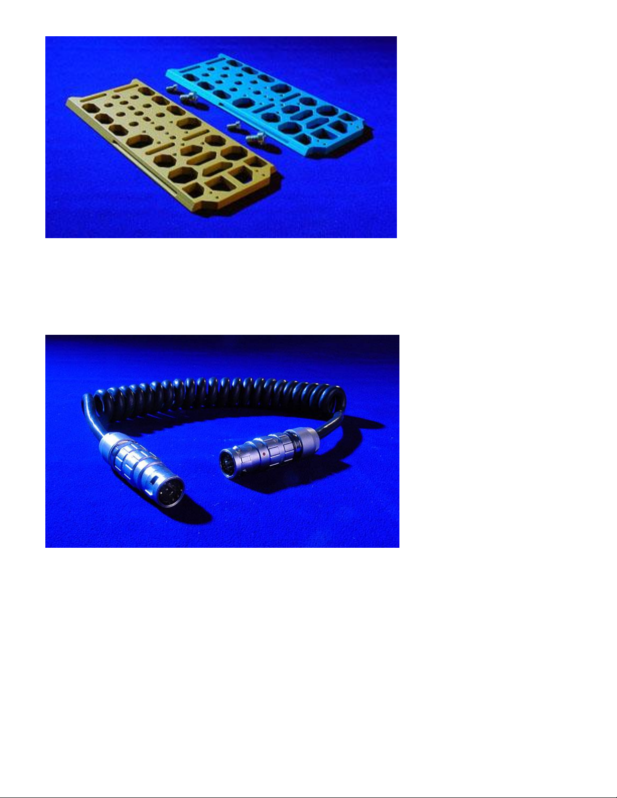
Glidecam Gold Sled Camera Plates (Video / Film)
9 Pin Lemo Central Post cable
6
Video/Power Connector Plugs (#s a, f)
For Monitors, Transmitters, Video IN and OUT, etc.
Receptacle: CIT# JBXEA0G04FCSDS or Lemo #ECG0B304CLM
Plugs for Cable: CIT #JBXFD0G04MCSDS or Lemo #FGG0B304CLCD
Pin#
1 Ground
2 +12 volts
3 Video
4 Video Ground
Video Only In/Out Connector (#G on diagram)
BNC 50 ohm
Pin#
Center Video
Ring Video Ground
Cam Batt CB/ Cam Batt CB#2 / Aux Batt (#s h, i, j)
Klixon 10

7
TABLE OF CONTENTS
1) Introduction 8-9
2) Mounting your Video or Movie Camera 10-11
3) Balancing your Glidecam GOLD SLED 11
Balancing the Horizontal Axis. 11-14
Balancing the Vertical Axis. 14-16
Using the Extension Post.. 16
Balancing the Vertical Axis when in Motion 17-18
4) Handling your Glidecam GOLD SLED 18
Connecting the Sled to the Support Arm. 18-19
5) Operating your Glidecam GOLD SLED 20-23
Shooting Styles. 23
Professional Usage 23
Video Tap. 24
Remote Control Follow Focus Devices.. 24
6) Shooting Tips 24
The use of a Wide Angle Lens Converter.. 25
Quick Release and Balance Plates 25
7) Warnings 25
8) Maintenance 26
10) Warranty 27
11) Glidecam Gold Connector List 28
12) Glidecam Gold Cable List 29

8
1) INTRODUCTION
Congratulations on your purchase of the Glidecam Gold Sled.
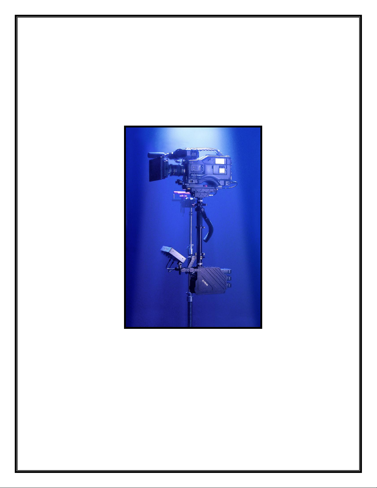
The new Glidecam Gold Sled TM holds any video or film camera weighing from 13 to 38 pounds. The Gold
Sled incorporates sophisticated engineering and precision machining to make it lightweight and strong. It
is designed with the same look and aesthetics as the Glidecam Gold Arm and Vest. The Gold Series sled
is available with one of the various daylight viewable, LCD monitors that we also sell (call us for details).
The black parts of the Glidecam Gold Sled are anodized black with certain parts hard coated black.
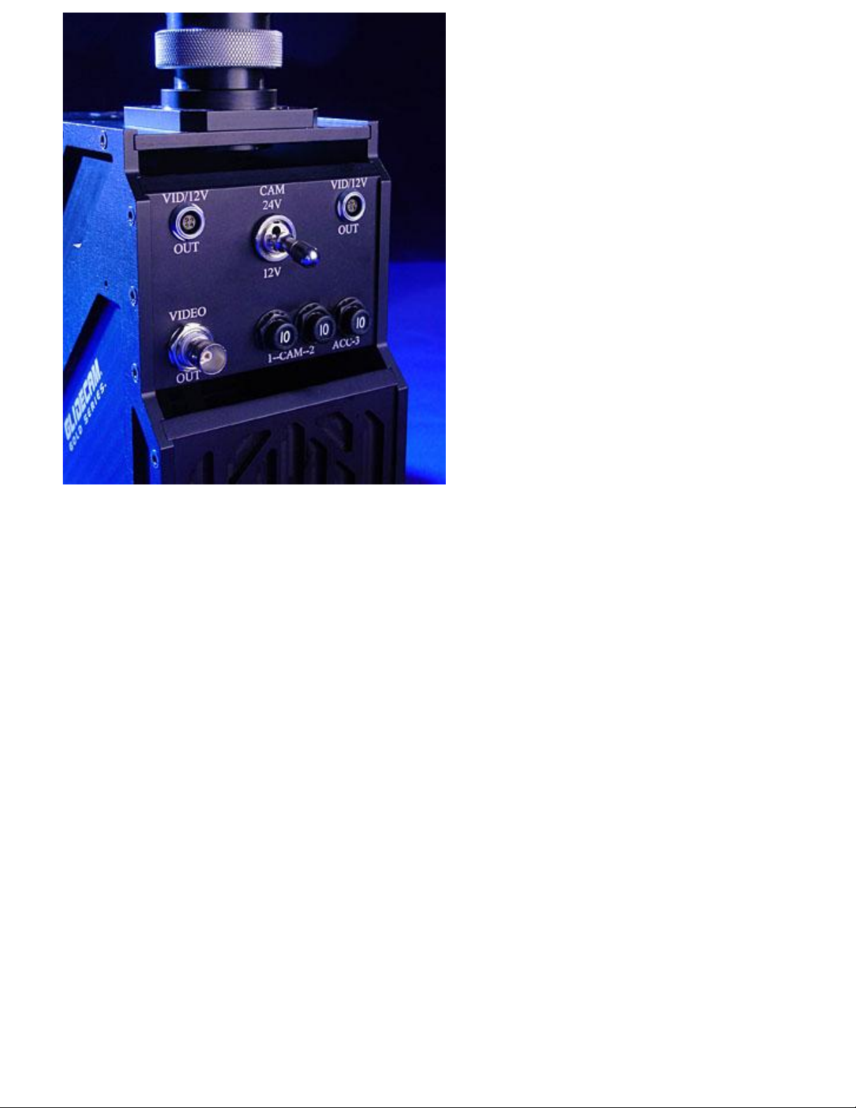
The Base of the Glidecam Gold Sled has a three NP-1 style battery system that delivers 12 volts to the
base (for the monitor) and delivers either 12 or 24 volts (switchable) to the head for use with video or film
cameras. The Base incorporates one BNC Video out connector, one 12/24 volt power switch, three circuit
breakers and two 4-pin “Lemo” style OB304 video/12 volt power out connectors. The Glidecam Gold
Sled monitor mounting bracket can be rotated 180 degrees, with no-tools adjustment so the monitor is
viewable during low mode operation.
The precision, x-y adjustable Head assembly utilizes low friction “Teflon” which is incorporated into its
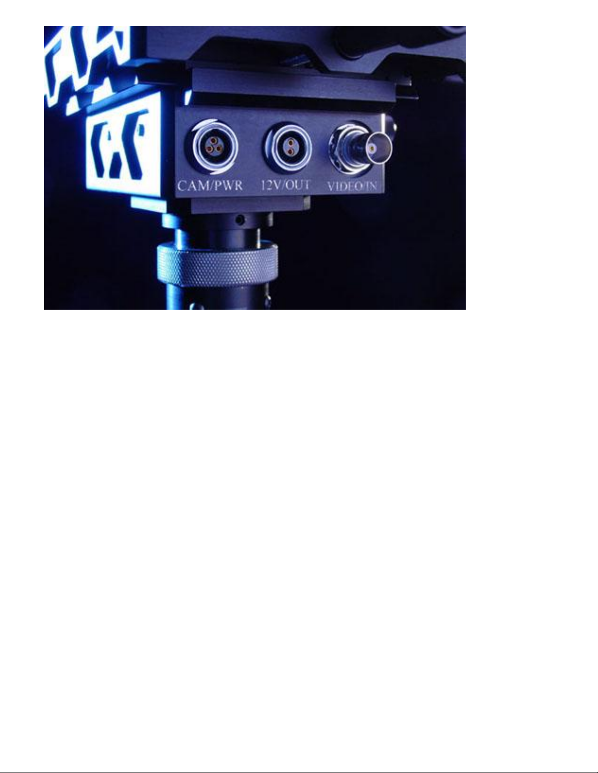
hard coat finish. The Head assembly’s back panel has a 3-pin “Lemo” 1B303 style with switchable 12/24
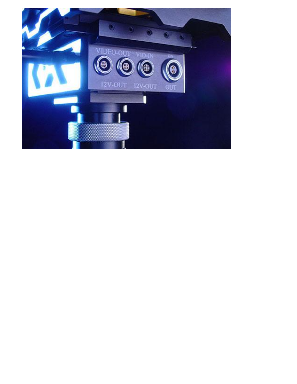
volt power, BNC video in, and a 2 pin “Lemo” 1B302 style with 12 volt out. The front panel has a 2-pin
“Lemo” 1B302 style with 12 volt out, two 4-pin “Lemo”OB304 style with video/power out and one 4-pin
“Lemo” OB304 video/power in connectors. The head also has a custom designed video distribution amp
installed for clear video signals. The Head also incorporates a drop in style dovetail camera plate for
quick front to back balance. Very, fine tuning, ergonomic knobs control front to back and side to side
balance adjustments.
The Sled’s “no-tools” precision Gimbal is made to top of the line quality. The Gimbal incorporates 4
bearings inside the handle to yoke connection (the tilt axis). There are 2 bearings on each side of the
yoke, providing 4 bearings for the roll axis. There are 2 central main bearings for the pan axis. This
doubles the Gimbal’s thrust capacity and creates less than a .0002” deflection off true center. All Gimbal
parts are machined within .0005” accuracy and are hard coat black. A very tight knurling has been
machined onto the Gimbal Tube to improve handling. An easy to replace soft foam covers the handle grip.
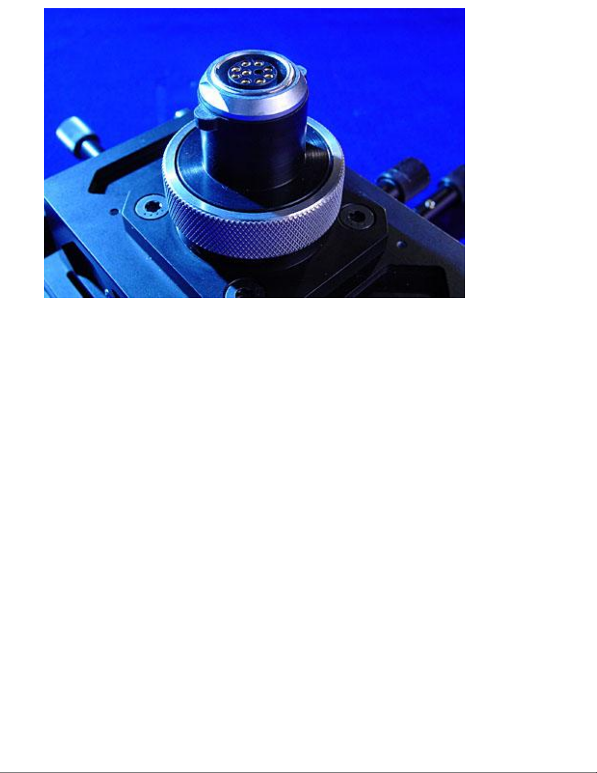
The Sled has a “no-tools” Telescoping Center Post. The top and bottom of the Post both have “no-tools”,
90-degree rotation, quick release connectors (bayonet style). This allows the Head and the Base of the
Sled to be removed quickly. The custom, shielded, wire coil assembly inside the post has 8-pin “Lemo”
style connectors on both ends for quick disconnect. The Center Post also incorporates an alignment pin as
part of the “no-tools” clamp that controls the extension of the Telescoping Post. This pin keeps the upper
and lower posts in alignment so the Head and Base of the Gold Sled are always parallel to each other.

9
NOTE: You will need a common Film Industry "C" STAND (also known as a Century Stand, or
Grip Stand), or a Film Industry LIGHT STAND so that later during the BALANCING procedures
and operation of the Glidecam GOLD SLED you will have something to attach and park your
GOLD SLED SLED onto. The "C" STAND or LIGHT STAND needs to terminate with a standard
5/8" diameter STUD on its uppermost riser. The STAND must also be of Film Industry quality in
the sense that it must be rugged and made of steel etc. Do not attempt to use a light weight
aluminum light stand, like the ones that are often sold at local amateur photography stores.
NOTE: Whenever you attach ANYTHING to the BASE PLATFORM, be it a BATTERY, or
MONITOR etc. make sure that it is attached so that it can not shift or move in place when the
GOLD SLED is in operation. If something that is attached to the GOLD SLED SLED shifts during
operation, it could throw the system out of balance, possibly causing unstable results.
When it comes to choosing a BASE PLATFORM configuration, one should take into account the general
principle that: The lighter the load on the top section of the Camera Mounting Assembly (the Sled),
the less counterweight required to counterbalance the Sled. In other words, if you reduce the weight
of the CAMERA PACKAGE attached to the top of the Sled, you’ll need less COUNTERWEIGHT at the
bottom of the Sled, (i.e. monitor and battery) thereby making the whole System lighter and more
comfortable to use.
You can reduce the weight of your CAMERA PACKAGE in several ways. First, the Camera you choose
to use with your GOLD SLED should be as light as possible. For instance, if you can choose between
shooting with a Camera that weighs 26 pounds, and a Camera that weighs 18 pounds, then definitely shoot
your footage with the 18 pound camera, given of course that the lighter Camera will be able to fulfill your
projects needs. Shooting with certain Film Formats and Tape Formats seems, at present, to sort of dictate
which camera weight you will be dealing with. An example being most of the Betacam and Betacam SP
camcorders. For now, they tend to weigh in around 15 pounds. In the 35mm and 16mm Film Camera
market there is a much wider range of camera weights available.
If you are unable to choose which Camera to shoot with, then you should a least try to lighten the overall
weight of your CAMERA PACKAGE. You can reduce the CAMERA’S weight by select a lightweight
PRIME LENS (preferably a wide angle lens) instead of a longer and heavier TELEPHOTO or ZOOM
LENS. Still another way to lighten the CAMERA PACKAGE is to remove any part of the camera's VIEW
FINDER SYSTEM that you will not be needing. Most Betacam Cameras have completely detachable
VIEWFINDERS. One could even lighten the load by using only a 20 minute tape or a 100 foot load of
film, but this is not at all necessary, for the weight gained from shooting with a 100 foot load instead of
400 is too small to be of any real concern.
Also it should be NOTED that moving the MONITOR AND BATTERIES closer to the CENTRAL
SUPPORT POST reduces the CAMERAS PANNING INERTIA, or in other words, moving the monitor
and battery closer to the POST, will allow you to PAN your CAMERA quicker. Moving the monitor and
battery away from the POST, increases PANNING INERTIA, thereby smoothing out, or causing the
PANNING motion to be slower.
 Loading...