

Page 1
Please read these user manual carefully before use
U
S E R
M
A N U A L
Multispot 330
Page 2

Page 3
Congratulations on cho osing our company product! We thank you for your custom.
◆Please not e that this product, as all the others in the rich my company range, has
been des igned and made wit h total quality to ensure excellen t performa nce and
best mee t your exp ec tations and requirem ents.
◆Carefully read this user manual in its entirety and keep it safe for future reference.
It is essential to know the information and comply with the instructions given in this
manual to ensure the fitting is installed, used and serviced correctly and safely.
◆
My company disclaims all liability for damage to the fitting or to other property or
persons deriving from installation, use and maintenance that have not been carried
out in conformity with this user manual, which must always accompany the fitting.
◆My company reserves the right to modify the characteristics stated in this user
manual at any time and without prior notice.
Contents
1 . S a fety i n f o r m a tion. . . . ..... . . ..... . . ..... . . ..... . . ..... . . ..... . . . .... . . . ..... . . ..... . . ..... . . ..... . . ..... . . ..... . . . ...2
2 . Tec h n i c al informati
on. . . ..... . . ..... . . ..... . . ..... . . ..... . . . .... . . . ..... . . ..... . . ..... . . ..... . . ..... . . ..... . . . .... . . 3
3 . A tta c h m e n t . . . ..... . . ..... . . ..... . . . .... . . . ..... . . ..... . . ..... . . ..... . . ..... . . ..... . . ..... . . . .... . . 5
4 . Ins ta ll a tion a nd c o n n e c ti n g . . ..... . . ..... . . ..... . . . .... . . . ..... . . ..... . . ..... . . ..... . . ..... . . ..... . . ..... . . . .... . . 6
5 . C ontr o l p a n e l . . . .... . . . ..... . . ..... . . ..... . . ..... . . ..... . . ..... . . . .... . . . ..... . . ....
. . . ..... . . ..... . . ..... . . . .... . . . ..... 7
6 . Me nu s etting.... . . . .... . . . ..... . . ..... . . ..... . . ..... . . ..... . . ..... . . . .... . . . ..... . . ..... . . ..... . . ..... . . ..... . . ..... . . . ..8
7 . C hannel func tion.. . . ..... . . ..... . . ..... . . . .... . . . ..... . . ..... . . ..... . . ..... . . ..... . . ..... . . . .... . . . ..... . . ..... . . ....1 2
8 . . . . ..... . . ..... . . ..... . . . .... . . . ..... . . ..... . . ..... . . ..... . . ..... . . ..... . . . .... . . . ...2 6
9 . . . . ..... . . ..... . . ..... . . . ..
. . . ..... . . ..... . . ..... . . . .... . . . ..... . . ..... . . ..... . . ..... 2 7
1 0 . . . . .... . . .... . .... . . .... . . .... . . .... . . .... . . .... . . .... . . .... . . .... . .... . . .... . . .... . . .... . . .... . . ...2 7
1 1 . . . . ..... . . ..... . . ..... . . . .... . . . ..... . . ..... . . ..... . . ..... . 2 8
1 2 . C ompa ny informati on .... . . ..... . . ..... . . . .... . . . ..... . . ..... . . ..... . . ..... . . ..... . . ..... . . ..... . . . .... . . . ..... . 2 9
and b o d y s ize
C irc u i t c on nec tin g dia gram
Duty e x onerati ve a n d c
opy r i g h t prote cti on
C leaning a n d m a i n tenanc e s
Tr o u be s ho oti n g
Page 4
• Installation
Make sure all parts for fixing the projector are in a good state of repair.
Make sure the point of anchorage is stable before positioning the projector.
The safety chain must be properly hooked onto the fitting and secured to the framework, so that,
if the primary support system fails,the fitting falls as little as possible.
If the safety chain gets used, it needs to be replaced with a genuine spare.
• MINIMUM DIST ANCE OF ILLUM INA TED OBJECTS
The projector needs to be positioned so that the objects hit by the beam of light are at least
12 metres from the lens of the projector.
• Minimu m distance from ammable materials
The projector must be posit
every point on the surface of the fitting.
Ioned so that any flammable materials are at least 0.2 metres from
• Mounting surfac es
It is permissible to mount the fitting on normally flammable surfaces.
• Maximu m ambient temperature
Do not operate the fixt ℃ure if the ambient temperature (Ta) exceeds 38 .
•Protection against electrical shock
Connection must be made to a power supply system fitted with efficient earthing (Class I appliance
according to standard EN 60598-1).
It is,moreover, recommended to protect the supply lines of the projectors from indirect contact and/or
shorting to earth by using appropriately sized residual current devices.
• Connection to ma ins supply
Connection to the electricit
Check that the mains frequency and voltage correspond to those for which the projector is designed
as given on the electrical data label.
This label also gives the input power to which you need to refer to evaluate the maximum number
of fittings to connect to the electricity line, in order to avoid overloading.
Don't use the power cable when the insulation is damaged.
It must be the manufacturer or distributor or the professional person to change the damaged power
cable in order to avoid any dangerous.
y mains must be carried out by a qualified electrical installer.
• T emperature of the external surface
The maximum temperature that can be reached on the external surface of the fitting, in a thermally
steady state, is 100℃.
• Maintenance
Before starting any maintenance work or cleaning the projector, cut off power from the mains
After switching off, do not remove any parts of the fitting, to avoid getting burnt for at least 30 minutes.
After this time the likelihood of the lamp exploding is virtually nill.
The fitting is designed to hold in any splinters produced by a lamp exploding. The lenses must be
mounted and, if visibly Damaged, they have to be replaced with genuine spares.
supply.
• Lamp
The fit
apparatus.
-Carefully read the "operating instructions" provided by the lamp manufacturer.
-Immediately replace the lamp if damaged or deformed by heat.
ting mounts a high-pressure lamp that needs an external igniter. This igniter is fitted onto the
• Battery
This product contains a rechargeable lead-acid battery. To preserve the environment, please d
the battery at the end of its life according to the regulation in force.
ispose
SAF ETY INFORMA TION
The products referred to in this manual conform to the European Community Directives to which
they are subject:
•Low Voltage 2006/95/CE
•Electromagnetic Compatibility 2004/108/CE
Pb
12m
t 100 ℃
c
t 38 ℃
a
Page 5

●
●
Power
495W(220V/50Hz)
●Lamp
- Brand:SIRIUS HRI 330W OSRAM
- Power:330W
- Colour temperature:3200K~8000K
- Average life 1500h
●Motors
16PCS mute sound motor.
●Channels
25/17/30 control channels
●
Beam:0~1.5° Spot:1.5~20°
●
Inputs
DMX 512/WIRELESS DMX 512(Apolegamic)
●Strobe
Double lens strobe(0.5-20 times/second)
●Dimmer
0-100% linear adjustment
●Prism
12-facet circular prism
●Lens
High presision optical lens
●Wash eect
Adjustable wash effects angle
●Travel
- PAN = 540°
- TILT = 230°
●Maximum speeds
- PAN = 2.9s/540°
- TILT = 1.5s/230°
●Resolution
- PAN = 2.11°
- PAN FINE = 0.008°
- TILT = 0.9°
- TILT FINE = 0.004°
Power supplies available
AC90-240V/50-60Hz
Beam angle
TECHNI CAL INFORMA TION
●
Automatic charging battery,IP could be set
without electricity.
●Features
Remote control lamp’s switch function,
display light and lamp’s using time,
automaticallay adjust cooling-fan’s speed,
Drop 60W power when strobe lens.
●IP20 protection rating
- Protected against the entry of solid bodies
larger than 12mm.
- No protection against the entry of liquids.
●Safety Devices
- Bipolar circuit breaker with thermal protection.
- Automatic break in power supply in case of
overheating or failed operation of cooling
system.
●Cooling
Forced ventilation with axial fans.
●Structure
Heat-proof plastic+module pressing alloy materials.
●CE Marking
- In conformity with the European Union Low Voltage.
- Directive 2006/95/CE and Electromagnetic
compatibility Directive 2004/108/CE.
●Two side handles for transportation.
●Device locking PAN and TILT mechanisms for
transportation and maintenance.
●Weights and size
Box Size:
450x430x730(mm)
N.W.:19.4kg G.W.:24kg
Flycase Size:
2PCS:900x630x715(mm)
N.W.:38.8kg G.W.:80.3kg
IP set
Page 6
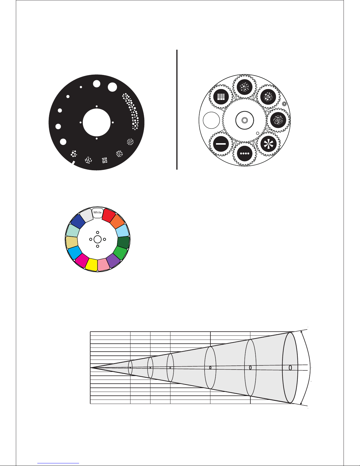
S tatic wh ee l( 1 w hi te + 1 2 g o bo) R o ta w he el (1 w h ite + 7 g ob o)
(please refer to the actual material) (please refer to the actual material)
P hoto metr ic D a ta :
Max highlig hts
Min high lig hts
Dis ta n ce m
Mi n. dia me te r m (f t in )
Ma x .d ia me te r m (f t i n)
White
Color Wheel: (please refer to the actual material)
White
1
2
3
4
5
6
7
1
2
3
4
5
6
7
8
9
10
11
12
Gobo si ze: outsi de15.9mm /inside1 0mm
1
2
3
4
5
6
78
10
11
12
13
14
9
Dark red
Nacarat
Light blue
Dark green
Green
Purple
Pink
Yellow
Magenta
Cyan
CTO2
CTB
Dark blue
Heat in sulation
9
7
5
3
1
0
1
3
5
7
9
0
0.76(2 '5" ) 0. 99( 3'2 ") 1.53(5 ') 2.05(6 '7" ) 2.46(8 ')0.52(1 '7" )
0
5.1( )16'7" 6. 8(2 2'3") 10. 2(3 3'5 ") 13.6(4 4'6 )" 17.0(5 5'8 )"3.4( 1 )1 ' 2"
0 10 15 30 4020 50
1.5020
0
4450(4 13)
89500( 831 8)
8000( 743 )
161000 (1 4963 )
2550(2 37)
41000( 381 0)
1450(1 35)
22600( 210 0)
780(7 2)
12800( 1190 )
17200( 15 99)
356000 (3 3086 )
Lux(fc)
Page 7
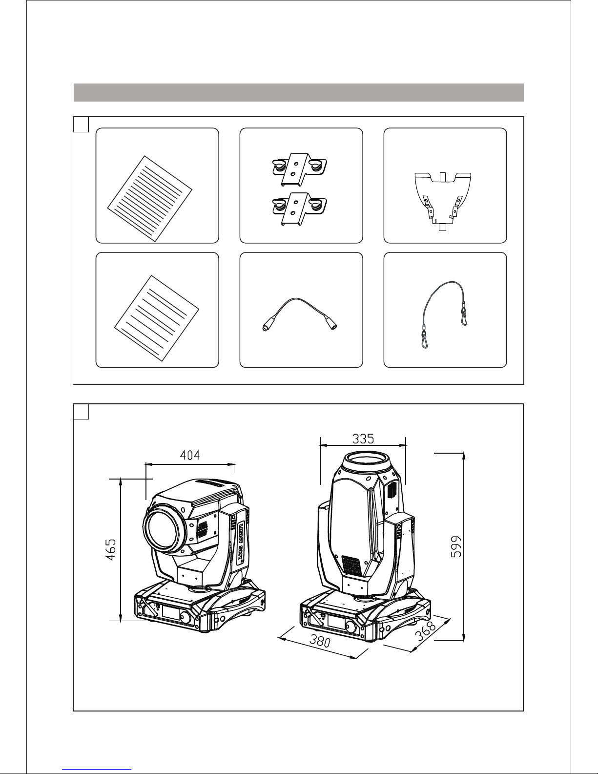
Attachment contents- Fig. 1
2
B o dy S i ze -- -F ig 2
A TT A CHMENT AND BOD Y SIZE
LAMP
1
S A F E T Y C O R D
DMX C A B L E
WA R R A NT Y C A R D
U S E R M ANUA L
B R A C K E T
(tted into projector)
Page 8
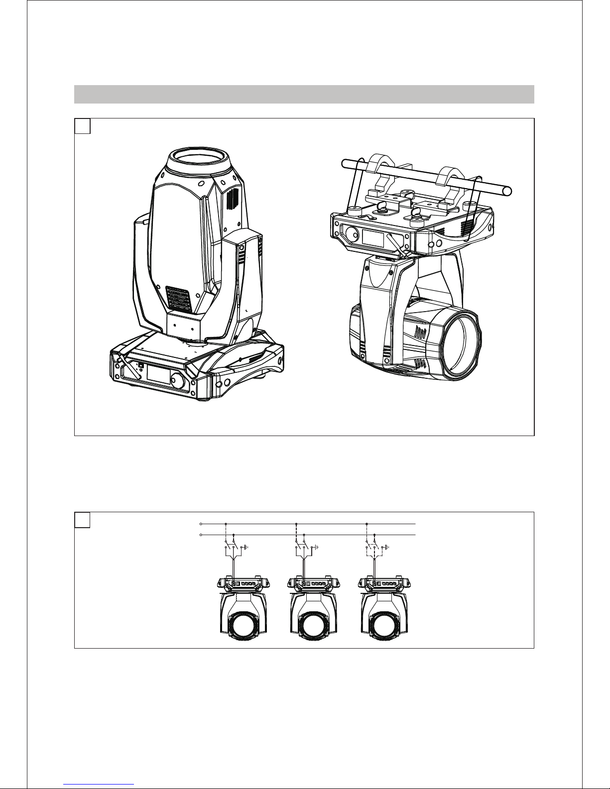
Installing the projector- Fig. 3
The projector can be installe
WARNING:with the exception of when the projector is positioned on the floor, the safety cable must be fitted.
This must be securely fixed to the support structure of the projector and then connected to the fixing point at
the centre of the base.
d on the floor resting on special rubber feet, on a truss or on the ceiling or wall.
3
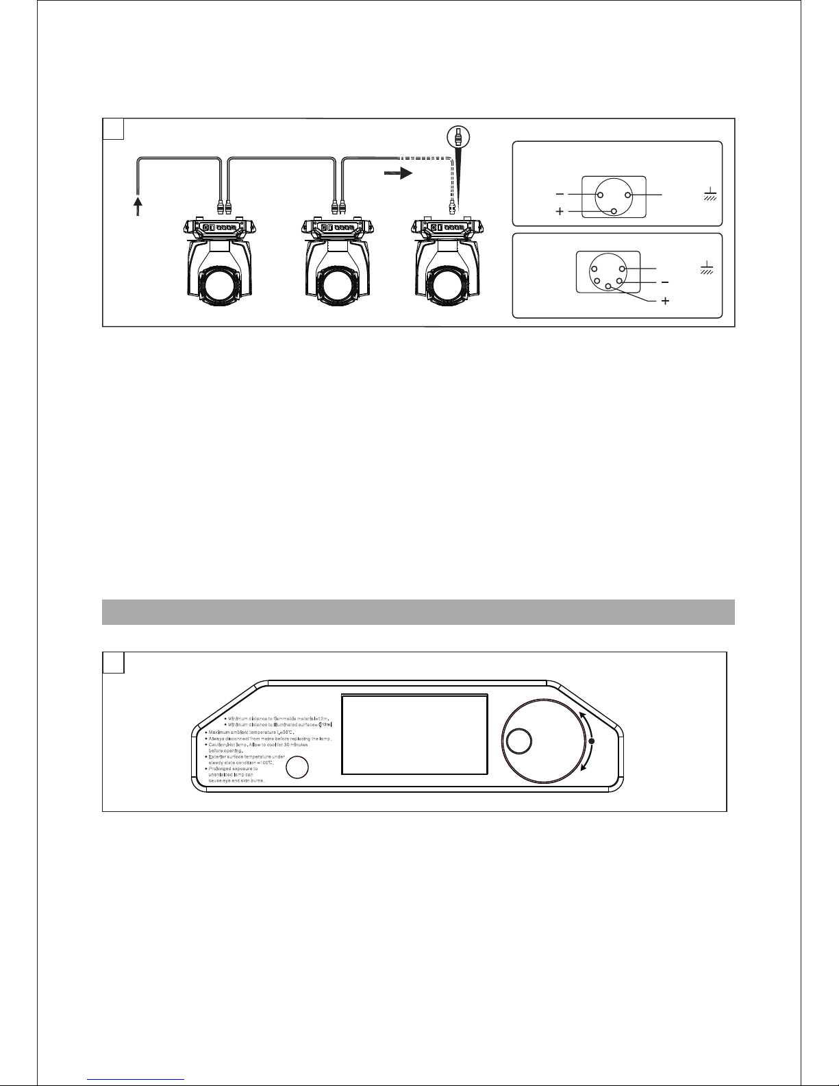
Mains
4
C onne c ti ng t o t he m a ins s u pp ply - --F ig 4
INST ALLA TION AND CONNECTING
L
N
Page 9
SCREEN
132
DMX 512
3 PIN
SIGNAL
SIGNAL
6
C onne c ti ng t o t he c o nt rol s ignal l in e ( DM X) - F i g. 5
◎ Please us e th e round 3 or 5- pin XLR plu gs & sockets o ff er ed by men u fa cture to co nn ect the f ir st
project or 's output t o the secon d pr ojector ' input and c on nect the se cond proj ec tor's out put to the
th ird pro je ctor's in pu t. And in th e sa me way for th e re st,ev en tually co nn ect the las t project or 's
output, al l the proje ctors are t og ether.
◎The proje ct ors's con trol sign al o utput or in put by usin g th e 3 or 5-pin XL R pug and soc ke t.If need t o
lengthe n th e communi cation ca bl e,pleas e make sure t he b oth side of 3 o r 5-pin plu g is o ne to one .
(one t
o one,two t o tw o,three t o three). Ot herwise ,the comm un ication c able will b e in terrupt ed.The
communi ca te cable is 2 -cord scr ee ned cable 7 5Ω resista nc e with each c ore is at lea st a 0 .5mm
diamete r.(C a uti on: All the insi de l eadin g wi re of 3 or 5-pi n XL R plug co ul dn't touc h ea ch othe r or
plinth) .
◎Recomme nd t o use the DMX s ignal ter mi nator for t he instal la tion to avo id the elec tr onic nois e dama
-ge the dig it al contro l signal. Si mply spea king,DM X te rminato r is an XLR con ne ctor with a 1 20Ω 1/2W
resisto r co nnected a cross pin 2 a nd 3 .Which is t hen plugg ed i nto the out put so
cket on the l as t projec
-tor in the c ha in.Refe r to the conn ec tion.
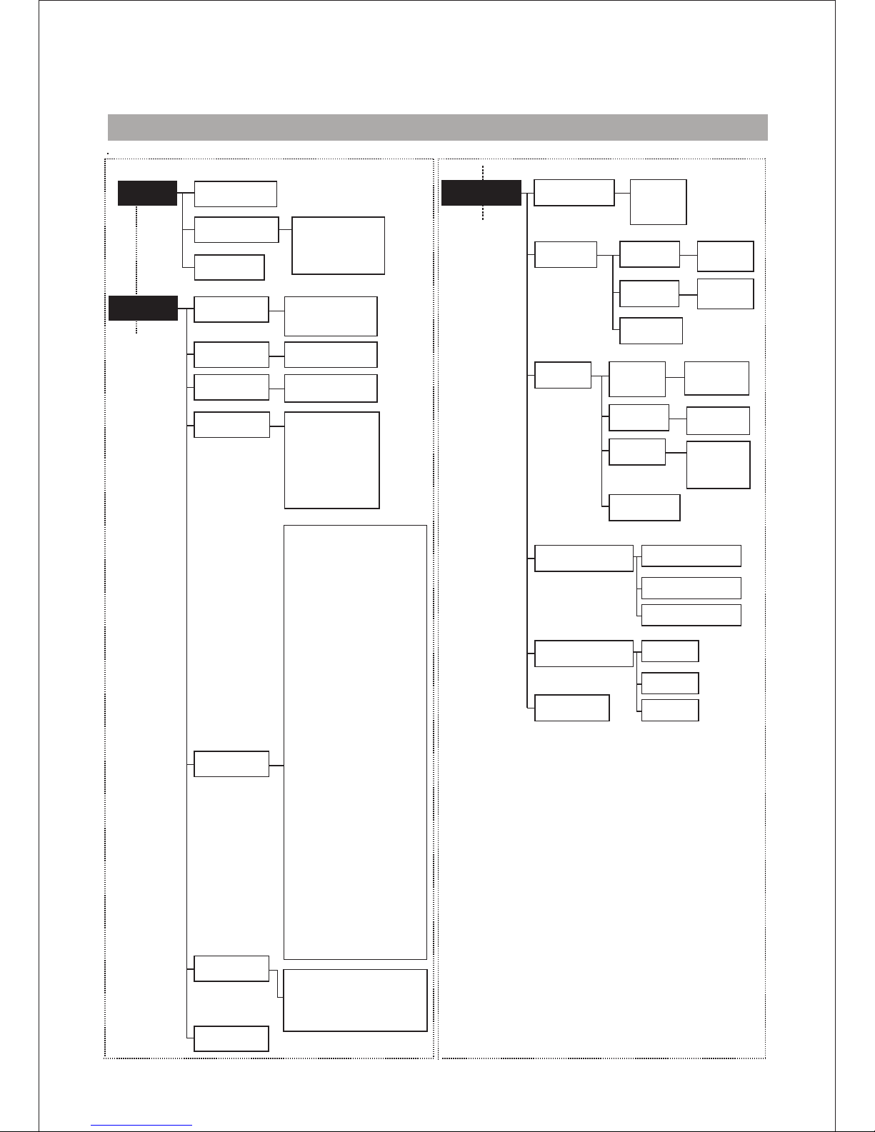
CO NTR OL P ANEL
SIGNAL
SCREEN
DMX 512
5 PIN
1
2
3
4
5
SIGNAL
U P A R R O WHE A D: P a ge u p o r i n c rea s e;
DO W N A R R O W H E A D: P a ge d own o r r e du c e;
E N T E R : O K F u ncti on
R e tu re(E S C ): E xit ( In t he c h oi ce s c reen )
P res s t h e s w itc h . T h e p r oje c to r s tarts r e s etti ng t h e e f fects . At the s a me t im e, t h e f ol lo wi ng
info rma ti o n s c roll s o n t he d is pl ay :
DMX 512
5
E N T E R
Mini mum dis tance t o flamm able ma teria l=12m .
Mini mum dis tance t o illum inate d surfa ce=
12m
W A R N I N G : H O T !
Maxi mum amb ient te mpera ture t = 38℃.
a
Alwa ys disc onnec t from ma ins bef ore rep lacin g the lam p.
Caut ion:H ot lamp . Allow to c ool for 3 0 minut es
b
efor e openi ng.
Exte rior su rface t emper ature u nder
s
tead y state c ondit ion =10 0 .
Prol onged e xposu re to
u
nshi elded l amp can
c
ause e ye and sk in burn s.
℃
GLG Lighting
Page 10
MENU SET TING(V1.0)
1
3
Setup
DMX Address
Information
Personal
P/T invert
Display
Shortcut module
Language
( )
语言
English 英文
Chinese(中文)
( )
Auto lamp on
Channel mode Standard(25CH)
Simple(17CH)
Extended(30CH)
Address:001-512
Lamp hours
RDM UID
Total:****H
Lamp:****H
LAMP:***C
3888:********
Arm1:****RPM
Arm2:****RPM
Lamp1:****RPM
Lamp1:****RPM
Lamp2:****RPM
Lamp3:****RPM
Zoom_B:V .
Dimmer_B: V*.**
P/T Board:V*.**
DIS Board:V *.**
* **
2
Reversal
Open
Return(ESC)
Temperature
Fans speed
DMX live
Return(ESC)
System version
Return(ESC)
Return(ESC)
Exit shortcut
OFF
ON
DMX
Pan invert
OFF
ON
OFF
ON
Tilt invert
Return(ESC)
Normal
Rota.180
Auto
BackLight
1.Pan
2.Pan fine
3.Tilt
4.Tilt fine
5.P/T speed
6.Function
7.Colour
8.Colour fi ne
9.C.T.O
10.Frost time
11.ColourTi me
12.Sta. Gobo.T
13.Prism zo om
14.Zoom time
15.Focus time
16.StaticGobo
17.Rota.Gobo
18.Gobo Rota.
19.Rota.GoboF
20.Prism
21.PrismR ota.
22.Frost
23.Zoom
24.Zoom fine
25.Focus
26.Focus fine
27.Auto focus
28.Shutter
29.Dimmer
30.Dimmer f ine
***
***
***
***
***
***
***
***
***
***
***
***
***
***
***
***
***
***
***
***
***
***
***
***
***
***
***
***
***
***
Auto Close(15s)
SINGLE PRISM
Execute shortcut
Return(ESC)
Power mode
280W
330W
350W
Page 11

4
Manual Control
Service
Return(ESC)
Calibration
Factory
6
Defualt
Calibrato n Def.
Time clean
Developer
Input:xxxx
Input:xxxx
Input:xxxx
Input:xxxx
Return(ESC)
C.T.O
Gobo Rota
Shutter
Colour
Stat. Gobo
Rota.Gobo
Dimmer
Frost
Zoom
Focus
Prism Zoom
PrismRota .
Prism
Pan
Tilt
Return(ES C)
±5. 00
±5. 00
±5. 00
±5. 00
±5. 00
±5. 00
±5. 00
±5. 00
±5. 00
±5. 00
±5. 00
±5. 00
±5. 00
±5. 00
±5. 00
1.Pan
2.Pan fine
3.Tilt
4.Tilt fine
5.P/T speed
6.Function
7.Colour
8.Colour fi ne
9.C.T.O
10.Frost time
11.ColourTi me
12.Sta. Gobo.T
13.Prism zo om
14.Zoom time
15.Focus time
16.StaticGobo
17.Rota.Gobo
18.Gobo Rota.
19.Rota.GoboF
20.Prism
21.PrismR ota.
22.Frost
2
3.Zoom
24.Zoom fine
25.Focus
26.Focus fine
27.Auto focus
28.Shutter
29.Dimmer
30.Dimmer fine
Reture(ES C)
000-255
000-255
000-255
000-255
000-255
000-255
000-255
000-255
000-255
000-255
000-255
000-255
000-255
000-255
000-255
000-255
000-255
000-255
000-255
000-255
000-255
000-255
000-255
000-255
000-255
000-255
000-255
000-255
000-255
000-255
Return(ES C)
LAMP ON/OFF
OFF
ON
Reset
Pan/Tilt reset
System reset
Gobo reset
Colour reset
Dimmer reset
Zoom reset
Return(ESC)
Channel control
Return(ESC)
5
Language
( )
语言
English 英文
Chinese(中文)
( )
Error list
Page 12

1
3
Setup
DMX Address
Information
Personal
P/T invert
Display
Shortcut module
Language
( )
语言
English 英文
Chinese(中文)
( )
Auto lamp on
Channel Mode Standard(25CH)
Simple(17CH)
Extended(30CH)
Address:001-512
Lamp Hours
RDM UID
Total:****H
Lamp:****H
LAMP:***C
3888:********
Arm1:****RPM
Arm2:****RPM
Lamp1:****RPM
Lamp1:****RPM
Lamp2:****RPM
Lamp3:****RPM
Zoom_B:V .
Dimmer_B: V*.**
P/T Board:V*.**
DIS Board:V *.**
* **
2
Reversal
Open
Return(ESC)
Temperature
Fans speed
DMX live
Return(ESC)
System version
Return(ESC)
Exit shortcut
Execute shortcut
Return(ESC)
OFF
ON
DMX
Pan invert
OFF
ON
OFF
ON
Tilt invert
Return(ESC)
Normal
Rota.180
Auto
BackLight
1.Pan
2.Pan fine
3.Tilt
4.Tilt fine
5.P/T speed
6.Function
7.Colour
8.Colour fi ne
9.C.T.O
10.Frost time
11.Colour time
12.Sta. Gobo.T
13.Prism ti me
14.Zoom time
15.Focus time
16.Static Gobo
17.Rota.Gobo
18.Gobo Rota.
19.Rota.GoboF
20.Prism
21.Prism Ro ta.
22.Frost
23.Zoom
24.Zoom fine
25.Focus
26.Focus fine
27.Auto focus
28.Shutter
29.Dimmer
30.Dimmer f ine
***
***
***
***
***
***
***
***
***
***
***
***
***
***
***
***
***
***
***
***
***
***
**
*
***
***
***
***
***
***
***
Auto Close(15s)
DOUBLE PRISM
Return(ESC)
Power mode
280W
330W
350W
Page 13

4
Manual Control
Service
Return(ESC)
Calibration
Factory
6
Defualt
Calibrato n Def.
Time clean
Developer
Input:xxxx
Input:xxxx
Input:xxxx
Input:xxxx
Return(ESC)
C.T.O
Gobo Rota.
Shutter
Colour
Stat.Gobo
Rota.Gobo
Dimmer
Frost
Zoom
Focus
Prism Zoom
PrismRota .
Prism
Pan
Tilt
Return(ES C)
±5. 00
±5. 00
±5. 00
±5. 00
±5. 00
±5. 00
±5. 00
±5. 00
±5. 00
±5. 00
±5. 00
±5. 00
±5. 00
±5. 00
±5. 00
1.Pan
2.Pan fine
3.Tilt
4.Tilt fine
5.P/T speed
6.Function
7.Colour
8.Colour fi ne
9.C.T.O
10.Frost time
11.ColourTi me
12.Sta.Gobo.T
13.Prism ti me
14.Zoom time
15.Focus time
16.StaticGobo
17.Rota.Gobo
18.Gobo Rota.
19.Rota.GoboF
20.Prism
21.Prism Ro ta.
22.Fros
t
23.Zoom
24.Zoom fine
25.Focus
26.Focus fine
27.Auto focus
28.Shutter
29.Dimmer
30.Dimmer f ine
Reture(ES C)
000-255
000-255
000-255
000-255
000-255
000-255
000-255
000-255
000-255
000-255
000-255
000-255
000-255
000-255
000-255
000-255
000-255
000-255
000-255
000-255
000-255
000-255
000-255
000-255
000-255
000-255
000-255
000-255
000-255
000-255
Return(ES C)
LAMP ON/OFF
OFF
ON
Reset
Pan/Tilt reset
System reset
Gobo reset
Colour reset
Dimmer reset
Zoom reset
Return(ESC)
Channel control
Return(ESC)
5
Language
( )
语言
English 英文
Chinese(中文)
( )
Error list
Page 14

CHANNEL FUNCTION
1 1 1
2
-
2
3
2 3
4
4
6
3 5
7
4 6
5 7
10
8
17
11
9
18
12
10
19
13
11
20
14
12
21
10
13
13
7
14
22
15
8
15
23
16
16
24
30CH17CH
25CH
CHANNEL
CHANNEL MODE
-
5
-
69
-
-
-
-
-
-
-
-
-
-
-
-
11
9
12
-
14
-
17
18
19
-
15
16
25
17
26
28
21
29
22
30
20
23
24
25
-
-
-
27
8
Pan
Pan fine
Tilt
Tilt fine
Pan/Tilt speed , P an/Tilt time
Power/Spe cial func tions
Colour whee l
Colour whee l - fine posi tioning
CTO
Frost time
Color time
Static gobo time
Prism zoom
Zoom time
Focus time
Static gobo w heel
Rotating go bo wheel
Rot. gobo ind exing and r otation
Rot. gobo ind exing and r otation - fine
Prism
Prism rotation and ind exing
Prism zoom
Frost
Zoom
Zoom - fine
Focus
Focus - fine
Auto focus (priority & d istance selection)
Shutter/ strobe
Dimmer inte nsity
Dimmer inte nsity - fin e
SINGLE PRISM
Page 15

DOUBLE PRISM
1 1 1
2
-
2
3
2 3
4
4
6
3 5
7
4 6
5 7
10
8
17
11
9
18
12
10
19
13
11
20
14
12
21
10
13
13
7
14
22
15
8
15
23
16
16
24
30CH17CH
25CH
CHANNEL
CHANNEL MODE
-
5
-
69
-
-
-
-
-
-
-
-
-
-
-
-
11
9
12
-
14
-
17
18
19
-
15
16
25
17
26
28
21
29
22
30
20
23
24
25
-
-
-
27
8
Pan
Pan fine
Tilt
Tilt fine
Pan/Tilt speed , P an/Tilt time
Power/Spe cial func tions
Colour whee l
Colour whee l - fine posi tioning
CTO
Frost time
Color time
Static gobo time
Prism time
Zoom time
Focus time
Static gobo w heel
Rotating go bo wheel
Rot. gobo ind exing and r otation
Rot. gobo ind exing and r otation - fine
Prism
Prism rotation and ind exing
Prism time
Frost
Zoom
Zoom - fine
Focus
Focus - fine
Auto focus (priority & d istance selection)
Shutter/ strobe
Dimmer inte nsity
Dimmer inte nsity - fin e
Page 16

25C H
DMX Va l ue P e rc e nt F un c tion
17C H 30C H
0-255
0-255
0-255
0-255
0-100
0-100
0-100
0-100
Pan movement by 540
Tilt movement by 230
Pan Fine
Tilt Fine
Pan/T ilt speed , Pan/T ilt time
1
3
121
3
-
-
2
4
53
Pan
Tilt
6
4 6
Power/Special functions
2
4
5
Fine control of pan movement
Fine control of tilt movement
Standard mode
Max. speed mode
Pan/Tilt speed mode
Speed from max. to min.
Pan/Tilt time mode
Time from 0.2 s to 25.5 sec.
0
1
2-255
2-255
0
0
0-100
0-100
Reserved
To activate following functions, stop in DMX value for at least 5 s.
No function
No function
Eco mode
Standard mode
Lamp power 350W
No function
No function
Blackout while pan/tilt moving
Disabled blackout while pan/tilt moving
Blackout while colour wheel moving
Disabled blackout while colour wheel moving
Blackout while gobo wheel moving
Disabled blackout while gobo wheel moving
Lamp On
Pan/Tilt reset
Colour system reset
Gobo wheels reset
Dimmer/Shutter
Zoom/focus/prism reset
Reserved
Total reset
Reserved
Lamp Off
Reserved
0-9
10-14
15-19
20-24
25-29
30-49
50-59
60-69
70-79
80-89
90-99
100-109
110-119
120-129
130-139
140-149
150-159
160-169
170-179
180-189
190-199
200-209
210-229
230-239
240-255
0-3
4-5
6-7
8-9
25-9
10-19
20-23
24-27
27-30
31-34
35-38
39-42
43-46
47-50
50-54
55-58
58-62
62-66
66-70
70-74
74-78
78-81
82-89
90-93
94-100
SINGLE PRISM
Page 17

25C H
DMX Va l ue P e rc e nt F u nc ti on
17C H 30C H
7
5 7
Colour wheel
Continual positioning
Open/white
Dark red
Nacarat
Light blue
Dark green
Green
Purple
Pink
Yellow
Magenta
Cyan
CTO2(2500K)
CTB(8000K)
Dark blue
Positioning
Dark red
Nacarat
Light blue
Dark green
Green
Purple
Pink
Yellow
Magenta
Cyan
CTO2(2500K)
CTB(8000K)
Dark blue
Forwards rainbow effect from fast to slow
No rotation
Backwards rainbow effect from slow to fast
Unuse range
Auto random colour selection from fast to slow
0
9
18
27
37
46
55
64
73
82
91
101
110
119
128-129
130-134
135-138
139-143
144-147
148-152
153-157
158-161
162-166
167-171
172-176
177-180
181-185
186-189
190-215
216-217
218-243
244-249
250-255
0
3
7
10
14
18
21
25
28
32
35
39
43
46
50
50-52
52-54
54-56
56-57
58-59
60-61
61-63
63-65
65-67
67-69
69-70
70-72
72-74
74-84
84-85
85-95
95-97
98-100
Colour wheel - ne positioning
C.T .O.
Frost time
Color time
Static gobo time
Fine positioning
Open(7200K→3600K)
Function is off
Time of frost movement (0.1 sec. --- >25.5 sec.)
Function is off
Time of colour wheel movement (0.1 sec. --- >25.5 sec.)
Function is off
Time of static gobo wheel movement (0.1 sec. --- >25.5 sec.)
8
9
8
9
10
11
12
6
0-255
0-255
0
1-255
0
1-255
0
1-255
0-100
0-100
0
0-100
0
0-100
0
0-100
-
-
-
-
-
-
-
1
2
3
4
5
6
78
10
11
12
13
14
9
Dark red
Nacarat
Light blue
Dark green
Green
Purple
Pink
Yellow
Magenta
Cyan
CTO2
CTB
Dark blue
Heat in sulation
Page 18

25C H
DMX Va l ue P e rc e nt Fun c tio n
17C H 30C H
Prism zoom
Zoom time
Focus time
Static gobo wheel
Zoom from min. to max.beam angle
Zoom from slow to fast beam angle
Function is off
Time of zoom movement (0.1 sec. --- >25.5 sec.)
Function is off
Time of zoom movement (0.1 sec. --- >25.5 sec.)
Open/hole
Positioning
Gobo1
Gobo2
Gobo3
Gobo4
Gobo5
Gobo6
Gobo7
Gobo8
Gobo9
Gobo10
Gobo11
Gobo12
white
white
Shaking gobos from slow to fast
Gobo1
Gobo2
Gobo3
Gobo4
Gobo5
Gobo6
Gobo7
Gobo8
Gobo9
Gobo10
Gobo11
Gobo12
white
white
Open/hole
Forwards gobo wheel rotation from fast to slow
No rotation
Backwards gobo wheel rotation from slow to fast
Unused range
Auto random gobo selection from fast to slow
13
14
15
16
7
10
0-127
128-100
0
1-255
0
1-255
0-3
4-9
10-15
16-21
22-27
28-33
34-39
40-45
46-51
52-57
58-63
64-69
70-75
76-81
82-87
88-95
96-103
104-111
112-119
120-127
128-135
136-143
144-151
152-159
160-167
168-175
176-183
184-191
192-199
200-201
202-221
222-223
224-243
244-249
250-255
0-1
1-3
3-5
6-8
8-10
10-12
13-15
15-17
18-20
20-22
22-24
25-27
27-29
29-31
32-34
34-37
37-40
40-43
43-46
47-49
50-52
53-56
56-59
59-62
62-65
65-68
69-71
72-74
75-78
78-78
79-86
86-87
87-95
95-97
98-100
0-50
51-100
0
0-100
0
0-100
-
-
-
-
--
Page 19

25C H
DMX Va l ue P e rc e nt Fun c tio n
17C H 30C H
Open/Hole (default)
Hole (flat field)
Gobo1
Gobo2
Gobo3
Gobo4
Gobo5
Gobo6
Gobo7
white
white
Rotation - set rotation on channel 12/9/17
Gobo1
Gobo2
Gobo3
Gobo4
Gobo5
Gobo6
Gobo7
white
white
Shaking gobos from slow to fast
Index - set indexing on channel 12/9/17
Gobo1
Gobo2
Gobo3
Gobo4
Gobo5
Gobo6
Gobo7
white
white
Shaking gobos from slow to fast Rotation - set rotation on channel 12/9/17
Gobo1
Gobo2
Gobo3
Gobo4
Gobo5
Gobo6
Gobo7
white
white
Open/hole
Forwards gobo wheel rotation from fast to slow
No rotation
Backwards gobo wheel rotation from slow to fast
Unused range
Auto random gobo selection from fast to slow
17811
0
1-4
5-7
8-10
11-13
14-16
17-19
20-22
23-25
26-28
29-31
32-34
35-37
38-40
41-43
44-46
47-49
50-52
53-55
56-59
60-67
68-75
76-83
84-91
92-99
100-107
108-115
116-123
124-129
130-137
138-145
146-153
154-161
162-169
170-177
178-185
186-193
194-199
200-201
202-221
222-223
224-243
244-249
250-255
0
0-1
1-2
3-3
4-5
5-6
6-7
7-8
9-9
10-10
11-12
12-13
13-14
14-15
16-16
17-18
18-19
19-20
20-21
21-23
23-26
26-29
29-32
32-35
36-38
39-41
42-45
45-48
48-50
50-53
54-56
57-60
60-63
63-66
66-69
69-72
72-75
76-78
78-78
79-86
87-87
87-95
95-97
98-100
Rotating gobo wheel
In the ra nge of 0-59 DM X the gobo sel ection spe ed is contro lle d by
the Effect S peed chann el.
Index - s et indexin g on channel 1 2/9/17
Page 20

25C H
DMX Va l ue P e rc e nt Fun c tio n
17C H 30C H
Rot. gobo indexing and rotation
Prism
Prism rotation and indexing
Frost
Prism zoom
Gobo indexing - set position on channel 11/8/16
Fine indexing (rotation)
18
19
20
21
22
10
11
13
12
14
15
17
16
0-255
0
1-127
128-129
130-255
0-100
0
0-49
49-50
51-100
Gobo indexing
No rotation
Forwards gobo rotation from fast to slow
No rotation
Backwards gobo rotation from slow to fast
0-255
0-19
20-49
50-75
76-105
106-127
128-135
136-143
144-151
152-159
160-167
168-175
176-183
184-191
192-199
200-207
208-215
216-223
224-231
232-239
240-247
248-255
0-7
7-19
19-29
29-41
41-49
50-52
53-56
56-59
59-62
62-64
65-68
69-71
72-74
75-78
78-81
81-84
84-87
87-90
90-93
94-96
97-100
0-255
0
1-127
128-129
130-255
0-100
0
0-49
49-50
51-100
0
1-179
180-189
190-211
212-233
234-255
0
0-70
70-74
74-82
83-91
91-100
0-127
128-255
0-50
51-100
Open position (hole)
Unused range
Unused range
12-facet circular rotating prism- Indexing
12-facet circular rotating prism-rotation
Prism/gobo macros
Macro 1
Macro 2
Macro 3
Macro 4
Macro 5
Macro 6
Macro 7
Macro 8
Macro 9
Macro 10
Macro 11
Macro 12
Macro 13
Macro 14
Macro 15
Macro16
Prism indexing - set position on channel 14/10/19
Prism indexing
Prism rotation - set position on channel 14/10/19
No rotation
Forwards prism rotation from fast to slow
No rotation
Backwards prism rotation from slow to fast
Open
Frost from 0% to 100%
100% frost
Pulse closing from slow to fast
Pulse opening from fast to slow
Ramping from fast to slow
Zoom from min. to max.beam angle
Zoom from slow to fast beam angle
0-100
-
-
912
13
Rot. gobo indexing and rotation - fine
Page 21

25C H
DMX Va l ue P e rc e nt Fun c tio n
17C H 30C H
Focus - ne
Shutter/ strobe
Dimmer intensity
Dimmer intensity - fine
Fine focusing
Select desired distance and effect on which you need to focus
and use "Focus" channel (20/15/25) to focus the image.
26
27
16 28
17 29
30
23
24
25
0-255 0-100
0
1
8
16
24
32
40
48
56
64
72
80
88
96
104
112
120
127
128-255
0
0
3
6
9
12
15
18
21
25
28
31
34
37
41
43
47
49
50-100
Autofocus Off
Rotating gobos & Hole (flat field)
10 metres
15 metres
20 metres
30 metres
40 metres
50 metres
50 metres upwards
Static gobos & Hole (default)
10 metres
15 metres
20 metres
30 metres
40 metres
50 metres
50 metres upwards
Infinity
Reserved
0-31
32-63
64-95
96-127
128-143
144-159
160-191
192-223
224-255
0-12
12-24
25-37
37-49
50-56
56-62
62-74
75-87
87-100
0-255 0-100
0-255 0-100
Shutter closed
Shutter open, full lamp power
Strobe-effect from slow to fast
Shutter open
Opening pulse in sequences from slow to fast
Closing pulse in sequences from fast to slow
Shutter open
Random strobe-effect from slow to fast
Shutter open, Full lamp power
Dimmer intensity from 0% to 100%
Fine dimming
-
-
-
21
22
Autofocus (priority & distance selection)
Zoom
Zoom - fine
Focus
14 23
24
2515
18
19
20
0-255 0-100
0-255 0-100
0-255 0-100
Zoom from max. to min.beam angle
Fine zooming
Continuous adjustment from far to near
-
Page 22

25C H
DMX Va l ue P e rc e nt Fun c tio n
17C H 30C H
0-255
0-255
0-255
0-255
0-100
0-100
0-100
0-100
Pan movement by 540
Tilt movement by 230
Pan Fine
Tilt Fine
Pan/T ilt speed , Pan/T ilt time
1
3
121
3
-
-
2
4
53
Pan
Tilt
6
4 6
Power/Special functions
2
4
5
Fine control of pan movement
Fine control of tilt movement
Standard mode
Max. speed mode
Pan/Tilt speed mode
Speed from max. to min.
Pan/Tilt time mode
Time from 0.2 s to 25.5 sec.
0
1
2-255
2-255
0
0
0-100
0-100
Reserved
To activate following functions, stop in DMX value for at least 5 s.
No function
No function
Eco mode
Standard mode
Lamp power 350W
No function
No function
Blackout while pan/tilt moving
Disabled blackout while pan/tilt moving
Blackout while colour wheel moving
Disabled blackout while colour wheel moving
Blackout while gobo wheel moving
Disabled blackout while gobo wheel moving
Lamp On
Pan/Tilt reset
Colour system reset
Gobo wheels reset
Dimmer/Shutter
Zoom/focus/prism reset
Reserved
Total reset
Reserved
Lamp Off
Reserved
0-9
10-14
15-19
20-24
25-29
30-49
50-59
60-69
70-79
80-89
90-99
100-109
110-119
120-129
130-139
140-149
150-159
160-169
170-179
180-189
190-199
200-209
210-229
230-239
240-255
0-3
4-5
6-7
8-9
25-9
10-19
20-23
24-27
27-30
31-34
35-38
39-42
43-46
47-50
50-54
55-58
58-62
62-66
66-70
70-74
74-78
78-81
82-89
90-93
94-100
DOUBLE PRISM
Page 23

25C H
DMX Va l ue P e rc e nt Fun c tio n
17C H 30C H
7
5 7
Colour wheel
Continual positioning
Open/white
Dark red
Nacarat
Light blue
Dark green
Green
Purple
Pink
Yellow
Magenta
Cyan
CTO2(2500K)
CTB(8000K)
Dark blue
Positioning
Dark red
Nacarat
Light blue
Dark green
Green
Purple
Pink
Yellow
Magenta
Cyan
CTO2(2500K)
CTB(8000K)
Dark blue
Forwards rainbow effect from fast to slow
No rotation
Backwards rainbow effect from slow to fast
Unused range
Auto random colour selection from fast to slow
0
9
18
27
37
46
55
64
73
82
91
101
110
119
128-129
130-134
135-138
139-143
144-147
148-152
153-157
158-161
162-166
167-171
172-176
177-180
181-185
186-189
190-215
216-217
218-243
244-249
250-255
0
3
7
10
14
18
21
25
28
32
35
39
43
46
50
50-52
52-54
54-56
56-57
58-59
60-61
61-63
63-65
65-67
67-69
69-70
70-72
72-74
74-84
84-85
85-95
95-97
98-100
Colour wheel - ne positioning
C.T .O.
Frost time
Color time
Static gobo time
Fine positioning
Open(7200K→3600K)
Function is off
Time of frost movement (0.1 sec. --- >25.5 sec.)
Function is off
Time of colour wheel movement (0.1 sec. --- >25.5 sec.)
Function is off
Time of static gobo wheel movement (0.1 sec. --- >25.5 sec.)
8
9
8
9
10
11
12
6
0-255
0-255
0
1-255
0
1-255
0
1-255
0-100
0-100
0
0-100
0
0-100
0
0-100
-
-
-
-
-
-
-
1
2
3
4
5
6
78
10
11
12
13
14
9
Dark red
Nacarat
Light blue
Dark green
Green
Purple
Pink
Yellow
Magenta
Cyan
CTO2
CTB
Dark blue
Heat in sulation
Page 24

25C H
DMX Va l ue P e rc e nt Fun c tio n
17C H 30C H
Prism time
Zoom time
Focus time
Static gobo wheel
Function is off
Time of prism movement (0.1 sec. --- > 5 sec.)
Time of prism rotation (0.1 sec. --- >25.5 sec.)
Function is off
Time of zoom movement (0.1 sec. --- >25.5 sec.)
Function is off
Time of zoom movement (0.1 sec. --- >25.5 sec.)
Open/hole
Positioning
Gobo1
Gobo2
Gobo3
Gobo4
Gobo5
Gobo6
Gobo7
Gobo8
Gobo9
Gobo10
Gobo11
Gobo12
white
white
Shaking gobos from slow to fast
Gobo1
Gobo2
Gobo3
Gobo4
Gobo5
Gobo6
Gobo7
Gobo8
Gobo9
Gobo10
Gobo11
Gobo12
white
white
Open/hole
Forwards gobo wheel rotation from fast to slow
No rotation
Backwards gobo wheel rotation from slow to fast
Unused range
Auto random gobo selection from fast to slow
13
14
15
16
7
10
0
1-50
51-255
0
0-19
20-100
0
1-255
0
1-255
0-3
4-9
10-15
16-21
22-27
28-33
34-39
40-45
46-51
52-57
58-63
64-69
70-75
76-81
82-87
88-95
96-103
104-111
112-119
120-127
128-135
136-143
144-151
152-159
160-167
168-175
176-183
184-191
192-199
200-201
202-221
222-223
224-243
244-249
250-255
0-1
1-3
3-5
6-8
8-10
10-12
13-15
15-17
18-20
20-22
22-24
25-27
27-29
29-31
32-34
34-37
37-40
40-43
43-46
47-49
50-52
53-56
56-59
59-62
62-65
65-68
69-71
72-74
75-78
78-78
79-86
86-87
87-95
95-97
98-100
0
0-100
0
0-100
-
-
-
-
--
Page 25

25C H
DMX Va l ue P e rc e nt Fun c tio n
17C H 30C H
Open/Hole (default)
Hole (flat field)
Gobo1
Gobo2
Gobo3
Gobo4
Gobo5
Gobo6
Gobo7
white
white
Rotation - set rotation on channel 12/9/17
Gobo1
Gobo2
Gobo3
Gobo4
Gobo5
Gobo6
Gobo7
white
white
Shaking gobos from slow to fast
Index - set indexing on channel 12/9/17
Gobo1
Gobo2
Gobo3
Gobo4
Gobo5
Gobo6
Gobo7
white
white
Shaking gobos from slow to fast Rotation - set rotation on channel 12/9/17
Gobo1
Gobo2
Gobo3
Gobo4
Gobo5
Gobo6
Gobo7
white
white
Open/hole
Forwards gobo wheel rotation from fast to slow
No rotation
Backwards gobo wheel rotation from slow to fast
Unused range
Auto random gobo selection from fast to slow
17811
0
1-4
5-7
8-10
11-13
14-16
17-19
20-22
23-25
26-28
29-31
32-34
35-37
38-40
41-43
44-46
47-49
50-52
53-55
56-59
60-67
68-75
76-83
84-91
92-99
100-107
108-115
116-123
124-129
130-137
138-145
146-153
154-161
162-169
170-177
178-185
186-193
194-199
200-201
202-221
222-223
224-243
244-249
250-255
0
0-1
1-2
3-3
4-5
5-6
6-7
7-8
9-9
10-10
11-12
12-13
13-14
14-15
16-16
17-18
18-19
19-20
20-21
21-23
23-26
26-29
29-32
32-35
36-38
39-41
42-45
45-48
48-50
50-53
54-56
57-60
60-63
63-66
66-69
69-72
72-75
76-78
78-78
79-86
87-87
87-95
95-97
98-100
Rotating gobo wheel
In the ra nge of 0-59 DM X the gobo sel ection spe ed is contro lle d by
the Effect S peed chann el.
Index - s et indexin g on channel 1 2/9/17
Page 26
25C H
DMX Va l ue P e rc e nt Fun c tio n
17C H 30C H
Rot. gobo indexing and rotation
Prism
Prism rotation and indexing
Frost
Prism time
Zoom
Zoom - fine
Focus
Gobo indexing - set position on channel 11/8/16
Fine indexing (rotation)
18
19
20
21
22
10
11
13
12
14
23
24
25
15
14
15
17
16
18
19
20
0-255
0
1-127
128-129
130-255
0-100
0
0-49
49-50
51-100
Gobo indexing
No rotation
Forwards gobo rotation from fast to slow
No rotation
Backwards gobo rotation from slow to fast
0-255
0-19
20-49
50-75
76-105
106-127
128-255
0-7
7-19
19-29
29-41
41-49
50-100
0-255
0
1-127
128-129
130-255
0-100
0
0-49
50-50
51-100
0
1-179
180-189
190-211
212-233
234-255
0
0-70
70-74
74-82
83-91
91-100
0
1-50
51-255
0
0-19
20-100
0-255
0-100
0-255 0-100
0-255 0-100
Open position (hole)
6-facet linear rotating prism -indexing
6-facet linear rotating prism- rotation
12-facet circular rotating prism- Indexing
12-facet circular rotating prism-rotation
Prism/gobo macros
No function
Prism indexing - set position on channel 14/10/19
Prism indexing
Prism rotation - set position on channel 14/10/19
No rotation
Forwards prism rotation from fast to slow
No rotation
Backwards prism rotation from slow to fast
Open
Frost from 0% to 100%
100% frost
Pulse closing from slow to fast
Pulse opening from fast to slow
Ramping from fast to slow
Function is off
Time of prism movement (0.1 sec. --- > 5 sec.)
Time of prism rotation (0.1 sec. --- >25.5 sec.)
Zoom from max. to min.beam angle
Fine zooming
Continuous adjustment from far to near
0-100
-
-
-
912
13
Rot. gobo indexing and rotation - fine
Page 27

25C H
DMX Va l ue P e rc e nt Fun c tio n
17C H 30C H
Focus - ne
Shutter/ strobe
Dimmer intensity
Dimmer intensity - fine
Fine focusing
Select desired distance and effect on which you need to focus
and use "Focus" channel (20/15/25) to focus the image.
26
27
16 28
17 29
30
23
24
25
0-255 0-100
0
1
8
16
24
32
40
48
56
64
72
80
88
96
104
112
120
127
128-255
0
0
3
6
9
12
15
18
21
25
28
31
34
37
40
43
47
49
50-100
Autofocus Off
Rotating gobos & Hole (flat field)
10 metres
15 metres
20 metres
30 metres
40 metres
50 metres
50 metres upwards
Static gobos & Hole (default)
10 metres
15 metres
20 metres
30 metres
40 metres
50 metres
50 metres upwards
Infinity
Reserved
0-31
32-63
64-95
96-127
128-143
144-159
160-191
192-223
224-255
0-12
12-24
25-37
37-49
50-56
56-62
62-74
75-87
87-100
0-255 0-100
0-255 0-100
Shutter closed
Shutter open, full lamp power
Strobe-effect from slow to fast
Shutter open
Opening pulse in sequences from slow to fast
Closing pulse in sequences from fast to slow
Shutter open
Random strobe-effect from slow to fast
Shutter open, Full lamp power
Dimmer intensity from 0% to 100%
Fine dimming
-
-
-
21
22
Autofocus (priority & distance selection)
Page 28

C i r c u i t c o n n e c t i n g d i a g r a m
S witc hed p o we r s u ppl y
P owe r i np ut
A C 90 ~24 0V
50/6 0H z
350P- XS V1.0 20141106
GND
+2 8
V
PE
Input
L
N
01GT- XY
V1.1 1 40926
GND
28
GND
28
GND
28
Displ ay boar d
01BS- 7M
V1.1 20 140926
GND
28
28 GND
330P- 8M V1. 1 20 141215
1
X Y b oard
P owe r o ut pu t
H ead d r ive b o ard
S ide d riv e b oar d
Page 29

C L E A N I N G A N D M A I N T E N A N C E S
●In order to ensu re the pr oject or could work norma lly.It shou ld be kep t clean a lways . It is recommended t hat the
fans and venti latio n in let sh ould be cleaned every 15 day s.The l ens and d ichroic colour filters s hould a lso be re g
-ularly clea ned to ma intai n an optimum light ou tput. Do not us e any type of solvent on dichr oic col our fil ters.It will
damage the pro jecto r.
●Suggestion :The co ntinu e usage of the light do n't exc eed 4 hou rs.Or i t will shorter the us age of th e lamp. Please
use the altern ative o perat ion to solve this pro blems .
●Please disco n
nect the power s upply w hen beg in to maintenaceor taked own the l ight. Please let the part s cool
down 10 minute a t least t hen beg in to install.If ne ed to rep lace th e lamp,please wait 10 minu te agai n at leas t to
let the lamp coo l down co mplet ely or which maybe burned do wn.
●Please inspe ct the le ns or oth er moving parts timing and k eep the m clear a nd static.If find a nythi ng dama ged or
losseness, must ch ange a la mp or fix the lamp in ord er to avo id the ac ciden t.
●The light use th e stron g cool sy stem. It is easy for th e dirty t o be coll ected .Please do cl ear the h ot-sa k one time
two week at leas t.
●After you use t
he light,ple ase che ck the in take place whether there a re some w astep aper,please clean it up,o r
the windmill w ill bre ak down a nd caus ing fire.
T R O U B E S H O O T I N G
It is rec ommen ded som e solut ion for some normal t roubl e shoot ing.Any unsolutioned p roble ms shou ld alwa ys
be handle by the p rofes siona l perso n.Disconnect th e power s upply b efore maintenan ce the li ght.
L am p o ff:
Please c heck if i nstal l the sui table lamp.
Please c heck th e conne ction o f the power supply or s witch i s ok.
Please c heck wh ether t he lamp will reach the end of th eir lif e can exp lode ,please repl ace a sam e descr iptio n
lamp.
Please m easur e if the po wer supply is enough.
Please c heck if t he oper ation i s correct.Pleas e wait 3
0 minutes at lea st till t he lamp c ool down enough,t hen
could the conn ect the p ower su pply,whic h could be normal work.
Please c heck wh ether t he DMX 51 2 controller pass t he "tur n on" ord er.
Please c heck th e conne ction o f the trigger circu it is loo se cont act.
Please c heck wh ether t he conn ected point of the tr igger p oint is l oose contact ,fas ter the c onnec t cable .
P lease chec k if the switc h of the tempe rature is da mag ed.
The l ig ht bea m i s d a rk ,no t i nh om og en eou :
When the l amp is to t he usag e life,the light is n ot enou gh,pl ease ch ange a new one for the sa me desc ripti on .
Please check t he refl ector p arts is dirty.Keep them clear.
Please m easur e if the po wer sup ply is enough.
Small ad justi ng is sui table for change height or s crew sy stem ti ll get a ideal light be am.
Check the bott om box dr iver bo ard "WK" socket if th e resis tance 0 b etwee n the two line.
Page 30

■T he l i gh t s h ad ow i s f o ggi ng :
◎Pleas e check the data on the DMX 512 co ntrol ler is su itable for the elec tric fo cus.
◎Please check t he mach enica l parts is jamging.After c leani ng,pl ease add some temperatur e -dura ble jui ce.
■T he l i gh t w orks i n te rru pt ly:
◎Pleas e check if the fan works norma lly or mo te clog ging.
◎Please check w hethe r the abs tract heat have the m ote clo gging .
◎Please check i f the lam p is to the u sage life.
◎Please check i f the pow er supp ly is enough,the connect ion of th e power s upply or the circuit are goo d.
◎Please check i f the swi tch of th e sup-temper
ature is good.
■T ho ugh t h e l igh t i s l igh ting ,bu t i t c ould n' t a ccep t the c o ntro l o rde r:
◎Please check t he star t code ad dress and the funct ion opt ion are c orrec t.
◎Please check w hethe r the com municate control cable i s ongoo d conne ction or the cable is too long o r inter rupt.
◎Please check t he cont rol sys tem is not valid,ch eck the s ingal a mplif ier of chain connec ted is va lid.
◎Please check w hethe r the com municate cable is too long o r the oth er equi pment is mutually c onjug ate.
◎Please arran ge the wi re well , ,Shorter the sign al cabl e ,put th e high vo ltage cable and low v ol
tage cable sep ar
-ately .
◎Add the signal a mplif y isola tor.
◎Signal cable i s used th e excel lent screening doublet ( Resis tance 7 5 Ω)
◎The end of the lig ht end an d the end r esistance.
◎When the lamp do n't coo l down en ough but do the incor rect op erati on will l et the trigger up to su per- hi gh
volta ge leak .It wil l damag e the electric circ uit and c ommun icate IC or CPU .Under this co nditi on,pl ease
change the PCB b oard.
■th e l ig ht c an't m o ve:
◎Please check i f the pow er supp ly is suitable for th e light v oltag e data.
◎Please check t he fuse o f input v oltage is defecti ve.
◎Please c
heck the light i f they ar e defor mating,inside p arts is b roken ,beco me wet...e tc will l ead the l oose co ntact.
◎Please check i f the ins ide lea d wire an d the connector is lo ose.
◎Please check t he elec tric pa rts (such as the swit ch,tr ansfo rmer,ballast,e lectr ic capa city,piez oresi stor, filter,
PCB board,co ntrol ler to mo tor) is short-cir cuit or b urn dow n.
■
◎
◎
◎
◎
◎
■
◎
◎
◎
◎Re-project or rese t.
P art o f t he p r oj ec to r c o uld n' t be r es po ns l ed t o t he c o ntrol li ng o r de r:
Plea se check the order is c orrec t to the mo ving.
Plea se check the mechan icalp art is de for
mation or loos e.
Plea se check the functi on to the m otor so cket is loose or driv e chip is b urn dow n.
Plea se check the wire of th e motor i s cut at zi g point.
Plea se check these func tion to t he moto r is damaged.
O n w or kin g, th e p an & til t c oul dn 't w o rk n o rma lly :
Plea se check accordin g to the ab ove ste p by step.
Plea se check the belt of th e X.Y is broke n.
Plea se check the X/Y direction data t o the rec eiver i s damage.
DUTY EX ONERA TIVE AND COPYRIGHT PR O TECTION
◇The lamp belon gs to con sumpt ion products that is not gua ran to kee p it in goo d repair
◇Any products b roken t hat did n't according to th e instr uctio n is not gu arantee to keep it in g ood rep air.
◇The commenta ry for al l the ins truction belong s to the su pplie r in fina l.
◇No authorize c an't co py.
◇
tee .
The informat ion in th is manu al may be changed in th e futur e,the c ompan y reserve the right t o chang e
the data witho ut any ad vise.
Page 31

GLG is a brand of GOED licht en geluid .
Goed licht en geluid Netherlands
Bornerbroeksestraat 457e
7609PK Almelo
Netherlands
Tel: 0031 (0)546 54 30 95
www.goedlichtengeluid.nl
info@goedlichtengeluid.nl
 Loading...