

Page 1
User Manual
KE EP THI S MAN UAL F OR F UT UR E N EE DS
tc
150°C
LED
0.2m
ta
40°C
MINISPOT 50
The following points have to be c on si dere d du ri ng t he i ns pe ct io n:
1) All scre ws f or i ns ta ll in g th e de vi ces or par ts of the d evice have t o be t ig ht ly
connected a nd m us t no t be corro de d.
2) There mu st n ot b e an y de fo rm at io ns o n th e ho using, color lenses, fixations and
installation spots (ceiling, sus pe ns io n, t ru ss in g) .
3) Mechanically moved par ts mus t no t sh ow a ny t ra ce s of wearing and must not
rot at e wi th u nb al an ce s.
4) The electric power supply cables must not show any damage, ma terial fatigue or
sediments.
Furt he r in st ru ct io ns d ep en di ng o n th e in st al la ti on s po t an d us ag e have t o be
adhered b y a sk il le d in st al le r an d an y safety pro bl em s ha ve t o be r em ov ed .
In orde r to m ak e th e li gh ts i n go od c on di ti on a nd e xt en d th e li fe t im e, w e su gg es t a
reg ul ar c le an in g to t he l ig ht s.
1) Clean the inside and outside lens each week to avo id t he wea kn en es s of t he l ig ht s
due to ac cu mu la ti on o f du st .
2) Clean the fan each week .
3) A detailed electric check by appro ve d el ec tr ic al e ng in eer each three m on th , ma ke
sure th at t he c ir cu it c on ta ct s ar e in g oo d co nd it io n, p re vent t he p oo r co nt ac t of
circu it f ro m ov er he at in g.
We re co mm en d a frequent cleanin g of th e de vice. Please use a moist, lint- free c loth.
Never u se a lc oh ol or solven ts .
There a re n o se r vi ce ab le par ts i ns id e th e de vi ce . Pl ea se r ef er t o th e in st ru ct io ns
under “Installation instructions”.
Should yo u need any spa re p ar ts , pl ea se o rd er g en ui ne p ar ts from y ou r lo ca l de al er.
MAINTENANCE AND CLEANING
10
Dis conne ct from m ains be fore st artin g maint enanc e opera tion.
CA U T I O N
.11.
Page 2

.01 .
If the device has been exposed to tem pe ra tu re c ha ng es d ue t o en vi ro nm en ta l ch an ge s,
do not switch i t on i mm ed ia te ly. T he a ri si ng c on de ns at io n co ul d da ma ge t he d ev ic e.
Leave t he d ev ic e switch ed o ff u nt il i t ha s re ac he d room temperature.
This device falls under pro te ct io n- cl as s I. T he re fo re i t is e ss en ti al t ha t th e de vi ce b e
eart he d.
The electric connection must carry o ut b y qu alified person.
The device shall only be used with rate vol tage and fre qu en cy.
Make su re t ha t th e available voltage is not higher than s ta ted at the end of t hi s ma nu al .
Make su re t he p ow er c ord is never crimped or damaged by sharp edg es . If t hi s wo ul d
be the case, re pl ac em en t of t he c ab le m us t be d on e by a n au th or iz ed d ea le r.
Always disconnect fro m th e ma in s, when the device is not in use or before c le an ing it.
Only handle the power cord by t he p lu g. N ev er p ul l ou t th e pl ug b y tu gg in g th e po we r
cord.
During initial start -u p so me s mo ke o r sm el l ma y ar is e. T hi s is a n or ma l pr oc es s an d
does not necessarily mean that the device is d ef ec ti ve, it s ho ul d de crease gradually.
Please don't pro je ct t he b ea m onto c om bu st ib le s ubstances.
Fixture s ca nn ot b e in st al le d on c om bustible substances, kee p mo re t ha n 50 cm
distance with wall for smooth air flow, s o th ere should b e no s he lter for fans and
ven ti la ti on for heat radiation.
If the exte rn al f le xi bl e cable or cord of t hi s lu mi na ir e is d am ag ed , it s ha ll b e ex cl us iv el y
rep la ce d by t he m an uf ac tu re r or h is s er vice a ge nt o r a si mi la r qu al if ie d pe rs on i n or de r
to av oi d a ha za rd .
This device has left t he f ac to ry in per fe ct c on di ti on . In o rd er to ma in ta in t hi s
condition and to en su re a s af e op er at io n, i t is a bs ol ut el y ne ce ss ar y for th e us er t o
follow the safety instructions and warning notes written in this user manual.
CA U T I O N
Bec arefu l with yo ur oper ation s.With a d anger ous vol tage yo u cansu ffer a
dan gerou s elect ric sho ck when t ouchi ng wire s!
IM PO RTAN T
Dam ages ca used by t he disr egard o f this us er manu al are no t subje ct to war ranty .
The d ealer w ill not a ccept l iabil ity for a ny resu lting d efect s or prob lems.
SAFETY INSTRUCTIONS
1
.10 .
Mod e/Cha nnel
Fun ction Valu es Des cript ion
Shu tter op en
Str obe eff ec t sl ow t o fa st
shu tter op en
Pul se-ef fe ct i n se qu en ce s sl ow to fas t
shu tter op en
Ran dom str obe eff ec t sl ow t o fa st
shu tter op en
Dim mer 0%. ..100 %
In( near) t o out(f ar)
OFF
ON
Rro tatin g from sl ow to fas t
No fu nctio n
No fu nctio n
No fu nctio n
No fu nctio n
All M otor re set
Sca n motor r eset
Col ors mot or rese t
Gob o motor r eset
Shu tter& Dimme r motor r eset
Oth er moto r reset
Int ernal p rogra m 1
Int ernal p rogra m 2
Int ernal p rogra m 3
Int ernal p rogra m 4
Int ernal p rogra m 5
Int ernal p rogra m 6
Int ernal p rogra m 7
Int ernal S ound pr ogram 1
32- 63
64- 95
96- 127
128 -159
160 -191
192 -223
224 -255
0-2 55
0-2 55
0-5
6-1 27
128 -255
0-1 9
20- 29
30- 39
40- 79
80- 84
85- 87
88- 90
91- 93
94- 96
97- 99
100 -119
120 -139
140 -159
160 -179
180 -199
200 -219
220 -239
240 -255
7
8
9
10
11
9
10
11
12
13
Shu tter
Dim mer
Foc us
Pri sm &
Rro tatin g
Spe cial
fun ction
Page 3

.02 .
Mov ing Hea d
Sig nal Cab le
Power Ca ble
Power Ou t
Han ging Ki t
Saf ety Cab le
Use r Manua l
1PC
1PC
1PC
1PC
1PC
1PC
1PC
①
②
③
④
⑤
⑥
⑦
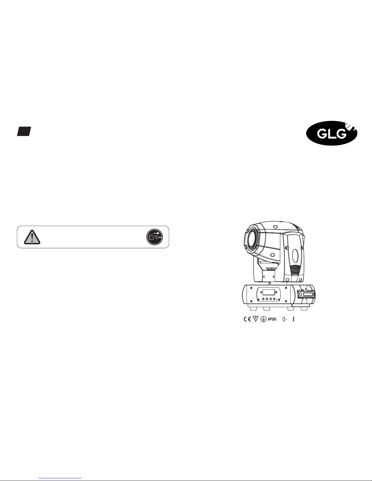
Thank you f or c hoosing our MINISPOT 5 0. F or you r ow n sa fe ty, p le as e read thi s
manual before i ns ta ll in g th e de vi ce. This manual covers the import an t in fo rm at io n on
installation and applications. Ple as e in st al l an d op er at e th e fi xt ure with following
instructions. Meanwhile, please kee p th is m an ua l we ll f or f ut ur e ne ed s.
The MINISPOT 50 i s ma de of a new type of h ig h te mp er at ur e st rength of e ng in ee ring
plastics and cast aluminum casing with n ic e ou tl oo k. The fixture i s de si gned and
manufacture d st ri ct ly f ol lo wi ng CE standard s, c om pl yi ng w it h in te rn at io na l st an da rd
DMX512 prot oc ol . It ’s av ai la bl e in de pe nd en tl y co nt ro ll ed a nd l in ka bl e wi th e ac h
other for operation. And it is applicable for large-scale live per fo rm an ce s, t he at er,
studio, nightcl ub s an d di sc os .
The MINISPOT 50 a do pt s a 50 W wh ite LED lamp whi ch f ea tu res high brightness and
stability. Ple as e care fu ll y un pa ck i t wh en y ou r ec ei ve t he f ix tu re and check whether it
is damaged during the transpor ta ti on . An d pl ea se c he ck w he th er t he f ol lo wi ng ite ms
are i nc lu de d in si de t he b ox :
UNPACKING
2
①
②
④
⑤
⑥ ⑦
③
Euro Standard
UK Standard
USA Standard
OPT IONAL
DMX CHANNELS
9
0-2 55
0-2 55
0-2 55
0-2 55
0-2 25
226 -235
236 -245
246 -255
0-1 5
16- 31
32- 47
48- 63
64- 79
80- 95
96- 111
112- 12 7
128 -189
190 -193
194 -255
0-9
10- 19
20- 29
30- 39
40- 49
50- 59
60- 69
70- 89
90- 109
110- 12 9
130 -149
150 -169
170 -189
190 -255
0-3
4-1 27
128 -131
132 -255
0-3 1
PAN Mo ve me nt
Fin e contr ol of Pan m oveme nt
Til t Mo ve ment
Fin e contr ol of Tilt m oveme nt
max t o min spe ed
bla ckout b y movem ent
bla ckout b y all whe el chan ging
no fu nctio n
Ope n / white
Col or 1
Col or 2
Col or 3
Col or 4
Col or 5
Col or 6
Col or 7
For wards r ainbo w effec t fr om f as t to s lo w
Col or rota tion st op
Bac kward s rainb ow effe ct f ro m sl ow t o fa st
Ope n
gob o 1
gob o 2
gob o 3
gob o 4
gob o 5
gob o 6
Gob o 1 shake s low to fa st
Gob o 2 shake s low to fa st
Gob o 3 shake s low to fa st
Gob o 4 shake s low to fa st
Gob o 5 shake s low to fa st
Gob o 6 shake s low to fa st
Rot . gobo wh eel con t. rota tion sl ow to fas t
no fu nctio n
For wards g obo rot ation f rom fas t to slow
Gob o rotat ion sto p
Bac kward s gobo ro tatio n from sl ow to fas t
Shu tter cl osed
Mod e/Cha nnel
Fun ction Valu es Des cript ion
8b
1
2
3
4
5
6
16b
1
2
3
4
5
6
7
8
Pan
Pan -fine
Til t
Til t- fi ne
Col or
whe el
Gob o
whe el 1
Gob o
rot ation
Spe ed
pan /tilt
.09 .
Page 4

.03 .
Fe at u re s
FEATURES & SPECIFICATIONS
3
• A 50W white L ED l am p
• 50000 hours life span and low power consumption
• 8/16 bit smooth and pre ci se r es ol ut io n fo r PAN /T ILT m ov em en t
• 360°/540°/630° PAN a nd 9 0° /1 80 °/ 27 0° T ILT m ov em en t
• Scan position memory, a uto re po si ti on a fter u ne xp ec te d mo ve me nt
• Spe cif ic op tic system wit h 11. 9° proje cti on an gle
• Improved opti cs an d flat beam fiel d
• 1 rot at ab le g ob o wh ee l wi th 6 r ot at ab le a nd i nt er ch an ge ab le g ob os p lu s op en w it h
speed adjustable, strea m ef fe ct , dithering effect and rot at ab le c lo ck wi se or
anticlockwise
• Gobo size 21.8mm (external dimensions)/14.5mm (inner dim en si on s)
• 1 color wheel with 7 colors pl us o pe n
• Vari ab le d ir ec ti on r ai nb ow e ff ec t wi th s pe ed a dj us ta bl e
• 2 meter t o in fi ni te e le ct ri c fo cu s
• 1 3-facet prism with va ri ab le s pe ed a nd d ir ec ti on
• 0-100% linear LED dimmer
• 25T/sec high speed LED shutter/stro be e ff ec t wi th v ar ia bl e sp ee d
• Pre se t va ri ab le /r an do m st ro be a nd d im mi ng p ul se e ff ec t
• 11/13 DMX channels USITT D MX -5 12
• DMX512, maste r- slave, a nd s ou nd a ctivat ed c on tr ol la bl e or a ut o op er at io n (7
built-in prog ra ms )
• DMX rec or de r an d ed it f un ct io n in te gr at ed
• Red b ac kgr ou nd L ED d is pl ay
• Powercon connector I N
• 3-pin XLR connector s IN/OUT
• Fan c oo li ng s ys te m
• Constant te mp er at ure re ad ou t an d ma na ge me nt f un ct io n
• 45°C max ambient te mperature
• IP20 prot ec ti on r at in g
• 55dB at 3’dB r at in g
• 1*hanging kit
Rotating gobos Colors
Red
Cya n
Gre en
Blu e
Ora nge
Yello w Whi te
Ros e
Car mine
MENU OPERATIONS
8
.08 .
For i nstal latio ns wher e th e DM X cab le has to r un a long d istan ce
or is i n an elec trica lly noi sy envi ronme nt , su ch as i n a
dis cothe que, it i s recom me nd ed to u se a DMX te rm ina tor. Thi s
hel ps in pre ve nti ng corr uptio n of the di gital c ontro l si gna l by
ele ctric al nois e. The DM X termi nator i s si mpl y an XLR pl ug with a
120 Ω r es is tor c onnec ted bet we en pi ns 2 and 3, which i s then
plu gged in to the ou tput XL R socke t of th e last fi xture i n th e cha in.
Ple ase see i llust ratio ns belo w.
1
2
3
PIN 3
PIN 2
120 Ω
Mod e
Up
Dow n
Ent er
LED D ISPLAY
MIC
ADD R
AUT O
SOU N
MIC
LOD A
VER
CAL I
MOD 1
MOD 2
ON/ OFF
S1
S2
S3
TXX X
PAN
TILT
VALU
SLAV
IP1 ~8
IP1 ~8
M-X X
ON/ OFF
V-1. 0~V-9. 9
CH1
CH2
CH3
630 /540/ 360
270 /180/ 90
A00 1~AXX X (AXXX )
ON/ OFF (SL AV)
ALO N (AU-A )
MAS T (AU-M )
ALO N (SO-A )
MAS T (SO-M )
0-- 255
0-- 255
0-- 255
MOD E
SET
DMX
RES T
SIG L
TEM P
DEG R
MEN U
DMX a ddres s setti ng
Sla ve
Alo ne sett ing
Mas ter set ting
Alo ne sett ing
Mas ter set ting
Mic s ensit ivity
Dat a reloa d
Sof tware v ersio n
Col or cali brati on
Gob o calib ratio n
Foc us cali brati on
16B m ode
8B Mo de
Res et
Wir ed mode
Wir eless M ode
Wir eless I N and wir ed OUT
Termp eratu re read ing
PAN an gle opt ions
TILT an gle opt ions
Page 5

11.9°Beam Angle LUX 0.0929=FC×
Photometric Beam Angle Data
.04 .
Spec ifi cations
Input Volt ag e:
LED Quantities:
Control S ig na l:
Control C ha nn el:
Pow er C on su mp ti on :
Dimensions:
Pac ki ng D im en si on s:
Net Wei gh t:
Gro ss W ei gh t:
AC9 0- 26 0V 5 0/ 60 Hz
1*50W white LED
DMX512, master-s la ve a nd s ou nd a ct iv at ed o r au to o pe ra ti on
11/13 DMX channels USITT D MX -5 12
55W
149(D)*270(W)*366(H)mm
350(D)*450(W)*240(H)mm
6.6kg
7.6kg
PHOTOMETRIC DATA
4
Beam
Diameter
ø 40.5 ø 81.5 ø 123 ø 164.5 ø 264
0m
1254 /
13500
11.9°
2.5 m 5m 7.5 m 20m10m 15m
312 /
3360
152 /
1640
97 /
1040
46 /
490
( FC/
LUX )
cm
195
180
184
270
366
97
155
149
DMX O utput
3-P in XLR So cket
DMX I nput
3-P in XLR So cket
1:G round
2:D ata(- )
3:D ata(+ )
1 2
3
12
3
1
2
3
1
2
3
COM MON
DMX +
DMX -
DMX 512 IN
3-P IN XLR
DMX 512 OUT
3-P IN XLR
.07 .
Reg ar dl es s of the rigging option you choose for your MINISPOT 50 , al wa ys b e su re to
secure yo ur f ix tu re w it h a sa fe ty c ab le . Th e fi xt ur e provid es a b ui lt -i n ri gg in g po in t fo r
a safety cable on the hanging bracket a s il lu st ra te d ab ov e. B e su re t o on ly u se t he
designate d ri gg in g point for the safety cable and never secure a sa fe ty c ab le t o a
carr yi ng h an dl e.
DMX-512 CONTROL CONNECTIONS
7
Con nec t the pr ovi ded XLR cable to th e fe ma le 3 -p in X LR o ut pu t of your controller and
the other side to t he m al e 3-pin XLR input of t he m ov in g he ad . You can c ha in m ul ti pl e
Moving head to get her thro ugh seri al li nk in g. T he c ab le n ee de d sh ou ld b e tw o co re ,
screen ed cable wi th XL R input and outp ut conne cto rs. Plea se refer to the dia gram bel ow.
DMX-51 2 con nec tion wit h DMX te rmi nator
DMX I N
DMX O UT
POW ER IN
Fus e
Pow er Swit ch
POW ER IN
DMX I N
Page 6

.05 .
Cautions: For added pro te ct io n mo un t th e fi xt ur es i n ar ea s ou ts id e wa lk in g pa th s,
seating are as , or i n ar ea s we re t he f ix tu re might be reached by unauthorized pers on ne l.
Before mo un ti ng t he f ix tu re t o an y su rf ac e, m ake su re t ha t th e in st al la ti on a re a ca n
hold a minimum point load o f 10 t im es t he d ev ic e’s w ei gh t.
Fixture i ns ta ll at io n mu st a lw ays be secured w it h a se co nd ar y safe ty a tt ac hm en t, s uc h
as an appro pr ia te s af et y ca bl e.
OPERATION INSTRUCTIONS
5
INSTALLATIONS
6
· The MINISPOT 50 i s fo r sp ot e ff ec t fo r on -s it e de co ra ti on p ur po se .
· Don’t turn on the fixture i f it ’s be en t hr ou gh s ev er e temper at ure differe nc e li ke
af ter transpor ta ti on b ec au se i t mi gh t da mage the light due to th e en vi ro nm en t
changes. So make su re t o op er at e th e fi xt ure until it is in normal temperature .
· This light should be ke ep a wa y fr om s tr on g sh ak in g du ri ng a ny t ra ns po rtation or
movem en t.
· Don’t pull up the light by only the head, or it might ca us e da ma ge s to the
mechanical pa r ts .
· Don’t expose the fixture in o ve rh ea t, m oi st ur e or e nv ir on me nt w it h to o mu ch d us t
when installing it. And don’t lay any power cables on the floor. Or it m ig ht c au se
electro ni c sh oc k to t he p eo pl e.
· Make su re t he i ns ta ll at io n pl ac e is i n go od s af et y co nd it io n be fo re i ns ta ll in g th e
fixture .
· Make su re t o pu t th e sa fe ty c ha in a nd c he ck w he th er t he s cr ew s are screw ed
pro pe rl y wh en i ns ta ll in g th e fi xt ure.
· Make su re t he l en s are in g oo d co nd it io n. I t’s recommended to rep la ce t he u ni ts i f
there a re a ny d am ag es o r se ve re s cr atch.
· Make su re t he f ix tu re i s op er ated by qualifie d pe rs on ne l wh o kn ow s th e fi xt ur e
before us in g.
· Kee p th e or ig in al p ac ka ge s if a ny s ec on d sh ip me nt i s ne ed ed .
· Don’t tr y to c ha ng e th e fi xt ur es w it ho ut a ny i ns tr uc ti on b y th e ma nu fa ct ur er o r
the appointed r ep ai ri ng a ge nc ie s.
· It is not in warranty range if there ar e an y ma lf un ct io ns f ro m no t fo ll ow in g th e
user manual to op er at e or a ny i ll eg al o pe ra ti on , like s ho ck s ho rt ci rcuit, electron ic
shock, l am p br oke, etc.
.06 .
Never s ta nd d ir ec tl y be lo w th e de vi ce w he n mo un ti ng , re mo vi ng , or s er vici ng t he
fixture .
fro m a ce il in g, o r se t on a f la t le ve l su rface (se e il lu st ra ti on b el ow ). B e su re this fi xt ure
is ke pt a t le as t 0. 5m ( 1. 5 ft) away fro m an y fl am mable mate ri al s (d ec oration etc. ).
Always use and install the supplied safe ty c ab le a s a sa fe ty m ea su re to pre ve nt
accidental damage and/or injur y in t he e ve nt t he c la mp f ai ls .
Mounting points: Overhead mounting requires e xt en si ve e xp er ie nc e, i nc lu di ng
amongst others calcu la ti ng wor ki ng l oad limits, a fine knowledge of t he i ns tallation
mater ia l be in g us ed, and periodic safety inspection of al l in st al la tion mater ia l an d th e
fixture . If y ou l ac k th es e qu al if ic at io ns , do n ot a ttem pt t he i ns ta ll at ion yo ur self.
Impro pe r in st al la ti on c an r es ul t in b od il y in ju r y.
Be sure t o co mp le te a ll r ig gi ng a nd i ns ta ll at io n pr oc ed ur es b ef ore connecting the
main powe r co rd t o th e ap pr op ri at e wa ll o ut le t.
Clamp Mounting: MINISP OT 50 p rovide s a un iq ue m ou nt in g br ac ket assembly that
integ ra te s th e bo tt om o f th e base, and the safety c ab le r ig gi ng p oi nt i n on e un it ( se e
the illustration below). When mounting t hi s fi xt ure to tr uss be sure to s ec ur e an
appro pr ia te ly r at ed c la mp t o th e in cl ud ed o me ga b ra cket u si ng a M 10 s crew fitted
throu gh t he c en te r ho le o f th e “H an gi ng K it ”. As a n ad de d sa fe ty m ea su re b e su re to
attached at least one pro pe rl y ra te d sa fe ty c ab le t o th e fi xt ur e us in g on o f th e sa fe ty
cable rigging point integrate d in t he b as e as se mb ly .
①
②
④
① Han ging Ki t
② Sat ety Cla mp
③ Saf ety Cab le
④ Scr ew
Turn ar ound Turn ar ound
③
 Loading...