

Page 1
Table of Contents
Pro Series C11
Combination Primary and
Backup Sump Pump System
Instruction
Manual &
Safety
Warnings
Important Safety Warnings and
Instructions
Electrical precautions 1
Battery preparation 1
Battery precautions 1
Introduction
Items included in system 2
Additional items needed 2
System specifications 2
Installing the Pipe and Pump 3
Battery Instructions 4,5
System Connections
Mounting the control unit 5
Connecting the backup pump 5
Installing the battery fluid sensor 5
Connecting the battery 6
Connecting the charger 6
Connecting the primary pump 6
Battery Maintenance 6
Product Operation
Float switches 6
1/8” weep holes 6
Controllers 6
Understanding the Warning
Lights and Alarms
Silencing the alarm during
an emergency 7
Power alarm 7
Battery fluid low 7
Refilling the battery 7
Pump was activated 8
Replacing the backup pump 8,9
Replacing the primary pump 10,11
System operating 11
Battery corroded or defective 11
Cleaning battery terminals 12
Replacing the battery 12,13
Test-reset button 13
Testing the System
Testing the backup float switch 13
Testing the primary float switch 13,14
Maintenance Check List 14
Parts & Service Information
Technical support 14
Replacement Parts Diagram & List 15
Troubleshooting Guide 16
Warranty 17
Page 2
Important Safety
Warnings & Instructions
SAVE THESE INSTRUCTIONS. This manual
contains important SAFETY WARNINGS and
OPERATING INSTRUCTIONS for the Pro Series
combination sump pump system. You will need
to refer to it before attempting any installation
or maintenance. ALWAYS keep these instructions
with the unit so that they will be easily
accessible.
Failure to read and follow these warnings and
instructions could result in property damage,
serious injury, or death. It is important to read
this manual, even if you did not install the Pro
Series combination sump pump system, since
this manual contains safety information
regarding the use and maintenance of this
product. DO NOT DISCARD THIS MANUAL.
ELECTRICAL PRECAUTIONS
WARNING
!
This installation must be in accordance with
the National Electric Code and all applicable
local codes and ordinances.
DANGER
!
Risk of electrical shock and fire hazard. May
result in death, serious injury, shock or burns.
To help reduce these risks, observe the
following precautions:
• DO NOT walk on wet areas of the basement
until all power has been turned off. If the
main power supply is in a wet basement, call
an electrician.
• ALWAYS disconnect the pumps from the power
source before servicing or making adjustments.
• ALWAYS unplug the control units and
disconnect the cables from the battery before
attempting any maintenance or cleaning.
• NEVER handle the pump or control unit with
wet hands or when standing on a wet or damp
surface while the pump is plugged into the
power source.
• MAKE SURE THERE IS A PROPERLY
GROUNDED RECEPTACLE AVAILABLE. This
pump is wired with a 3-prong grounded plug.
To reduce the risk of electric shock, be certain
that it is only connected to a properly
grounded 3-prong receptacle. If you have a 2prong receptacle, have a licensed electrician
replace it with a 3-prong receptacle according
to local codes and ordinances.
• NEVER bypass grounding wires or remove the
ground prong from the plug.
• DO NOT use an extension cord. The electrical
outlet should be within the length of the
pump's power cord, and at least 4 feet above
the floor level to minimize potential hazards
from flood conditions.
• DO protect the electrical cord from sharp
objects, hot surfaces, oil and chemicals. Avoid
kinking the cord.
• MAKE SURE the supply circuit has a dedicated
fuse or circuit breaker rated to handle the
power requirements noted on the nameplate of
the pump.
CAUTION
To reduce the risk of hazards that can cause
injury or property damage, observe the
following precautions:
• DO NOT use the power cord or strain relief to
carry the pumps. Use the handle.
• DO NOT pull on the cord to disconnect the
system or the pump. Pull the plug.
• DO NOT expose the control units to moisture,
rain or snow.
• DO NOT operate the pumps or control units if
they have been damaged in any way.
• DO NOT use pumps in pits handling raw
sewage, salt water, or hazardous liquids. This
product is rated for ground water use only.
• DO NOT disassemble the pumps or control
units. When service is required, contact
Glentronics' technical support at 800-991-
0466. Return the product to the manufacturer
for any repairs at the following address:
Glentronics, Inc.
645 Heathrow Drive, Lincolnshire, IL 60069
BATTERY PREPARATION
WARNING / POISON
!
Sulfuric acid can cause blindness or severe
burns. Avoid contact with skin, eyes or
clothing. In the event of accident, flush with
water and call a physician immediately. KEEP
OUT OF REACH OF CHILDREN.
To help reduce these risks, observe the
following precautions:
• Someone should be within range of your voice
or close enough to come to your aid when you
work near a lead-acid battery.
•
Have plenty of fresh water and soap nearby in
case battery acid contacts skin, clothing or eyes.
• Wear eye and clothing protection and avoid
touching your eyes while working with battery
acid or working near the battery.
• If battery acid contacts skin or clothing, wash
immediately with soap and water. If acid enters
eye, immediately flood eye with running cold
water for at least 15 minutes and get prompt
medical attention.
• Battery posts and terminals contain lead, lead
compounds or chemicals known to the State of
California to cause cancer, birth defects or
other reproductive harm. Wash hands after
handling. See https://www.p65warnings.ca.gov/
for more information.
BATTERY PRECAUTIONS
DANGER
!
Explosive gases could cause serious injury
or death. Cigarettes, flames or sparks could
cause battery to explode in enclosed spaces.
Charge in well-ventilated area. Always shield
eyes and face from battery. Keep vent caps
tight and level.
To help reduce these risks, observe the
following precautions:
• NEVER smoke or allow a spark or flame in the
vicinity of the battery.
• Use the Pro Series control unit for charging a
LEAD-ACID battery only. DO NOT use the
control unit for charging dry-cell batteries that
are most commonly used with home
appliances.
• Be sure the area around the battery is wellventilated.
• When cleaning or adding water to the battery,
first fan the top of the battery with a piece of
cardboard or another non-metallic
blow away any hydrogen or oxygen gas that
may have been emitted from the battery.
• DO NOT drop a metal tool onto the battery. It
might spark or short-circuit the battery and
cause an explosion.
material to
• Remove personal metal items such as rings,
bracelets, watches, etc. when working with a
lead-acid battery. A short circuit through one
of these items can melt it causing a severe
burn.
• ALWAYS remove the charger from the electrical
outlet before connecting or disconnecting the
battery cables. Never allow the rings to touch
each other.
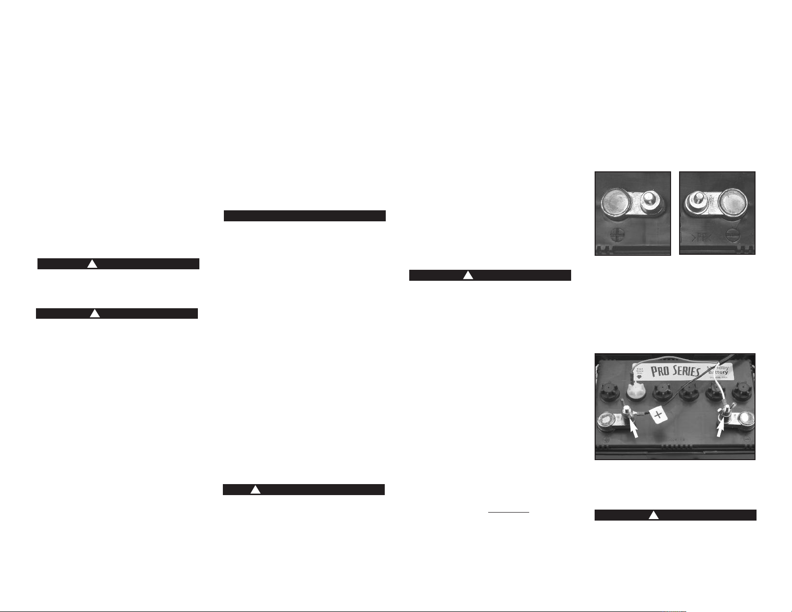
• Check the polarity of the battery posts. The
POSITIVE (+) battery post usually has a larger
diameter than the NEGATIVE (-) post.
POSITIVE POST HAS
LARGER DIAMETER
• When connecting the battery cables, first
connect the small ring on the end of the
WHITE wire to the NEGATIVE (-) post of the
battery, and then connect the large ring on
end of the BLACK wire to the POSITIVE (+) post
of the battery.
POSITIVE
POST
• ALWAYS keep the cover secured on the battery
box by slipping the tabs through the fittings
on the front and back of the box.
Do not use system to pump flammable or
explosive fluids such as gasoline, fuel oil,
kerosene, etc. This product is rated for
ground water use only.
NEGATIVE POST HAS
SMALLER DIAMETER
DANGER
!
NEGATIVE
POST
Page 1
Page 3
Introduction
The Pro Series Pair of Pumps combination system
is designed to provide both primary and backup
pumping capabilities. The primary pump will
operate as long as it is receiving AC power. If
the power is interrupted, or more water is
coming into the sump than the AC pump can
handle, the backup sump pump will begin
pumping automatically. The backup system has
unique monitoring features that diagnose a
problem and sound an alarm. A light on the
display panel of the control unit will indicate the
cause of the alarm and the corrective action.
The two systems have been pre-assembled for
easy installation.
For added reliability, the float switches have, not
one, but two floats. Should one float fail to
operate, the second float automatically activates
the pump.
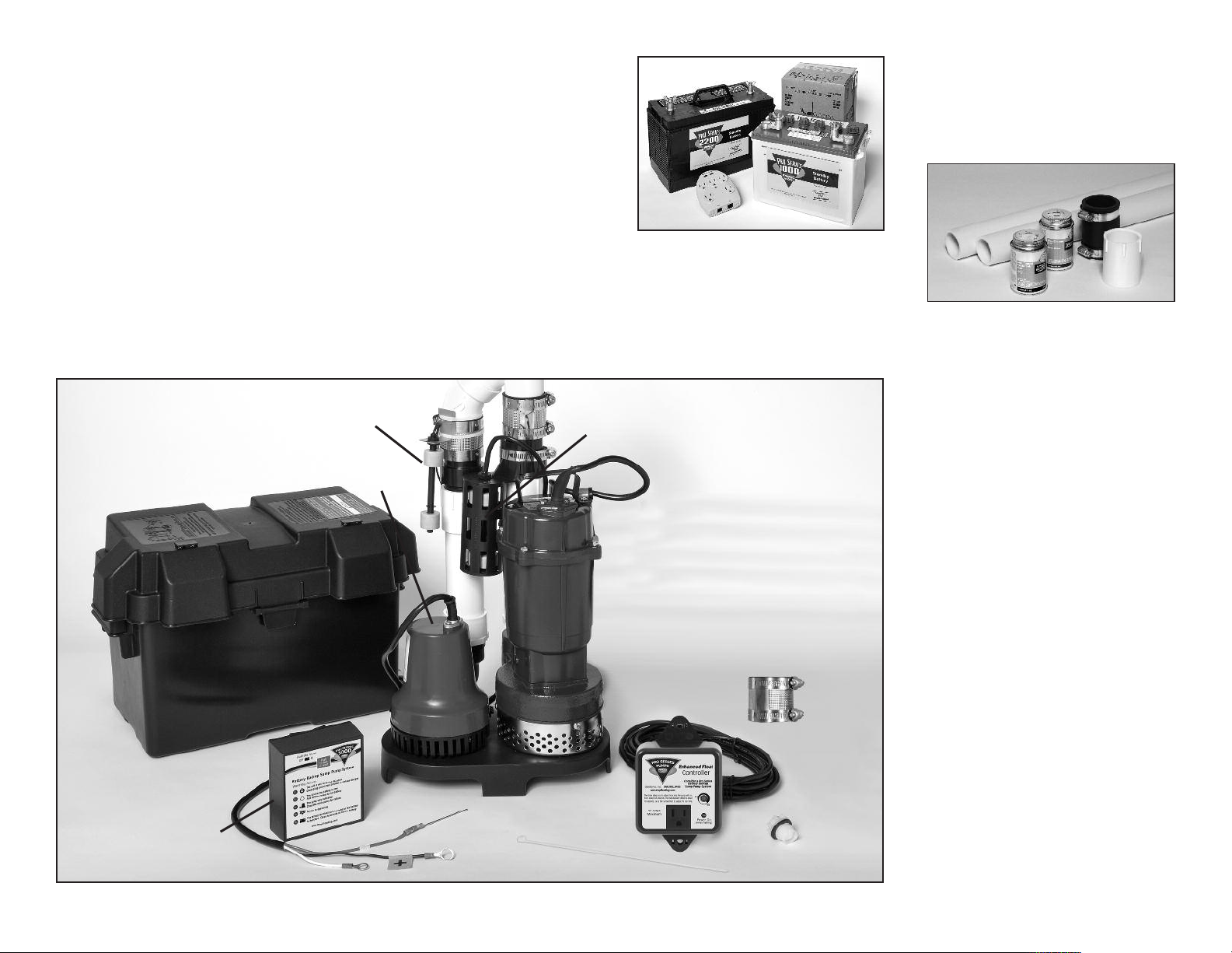
The Pair of Pumps Combination Sump Pump
System includes:
• A 1/3 HP primary pump with a caged dual
float switch, and a blue piggyback controller
that plugs into the wall outlet
• A blue backup pump
• A black control unit with a battery fluid
sensor, a dual float switch, and battery
cables
• A battery charger
• A battery cap with a hole to accommodate
the fluid sensor
• A battery box
• A no hub coupling
You will also need to supply:
• A PHCC Pro Series B-1000, B-2200 or B12-90
standby battery
Backup Pump
Float Switch
• A surge protector (recommended)
• Six (6) quarts of 1.265 specific gravity
DO NOT use an automotive battery with
this system
Primary
Pump Float
Switch
The internal construction of some wet cell or
maintenance free (AGM) batteries may not
be compatible with this system. Glentronics,
Inc. cannot guarantee the compatibility of
other brands of batteries. The use of a PHCC
Pro Series battery is HIGHLY recommended.
battery acid
For some installations you may need
additional items:
• 1-1/2” rigid PVC pipe to connect to the
existing plumbing
• A PVC pipe connector or a rubber union
• PVC pipe cleaner and cement
Battery Box
Controller
Backup
Pump
Backup
Pump
Fluid Sensor
Battery Wires
Primary
Pump
Primary
Pump
Controller
Cable Tie
System Specifications
Power supply requirements.......115 volts, 60 Hz
AC pump pumping capacity..... 2770 GPH @ 10’
............................................. 46 GPM @ 10’
DC pump pumping capacity..... 1000 GPH @ 10’
............................................. 17 GPM @ 10’
Overall dimensions................. 11” W x 23¾” H
No Hub
Coupling
Battery Cap
Page 2
Page 4
Installing the Pipe and Pump
Glentronics, Inc. 800.991.0466
www.stopflooding.com
Power On
(
when flashing)
12 Amps
Maximum
10
45
Enhanced Float
Controller
C
onsider a Pro Series
B
attery Backup
S
ump Pump System
A
djust pump timer from 5-45 seconds
using a flat head screw driver.
Seconds
233/4”
CUT
PVC TO
THIS
LENGTH
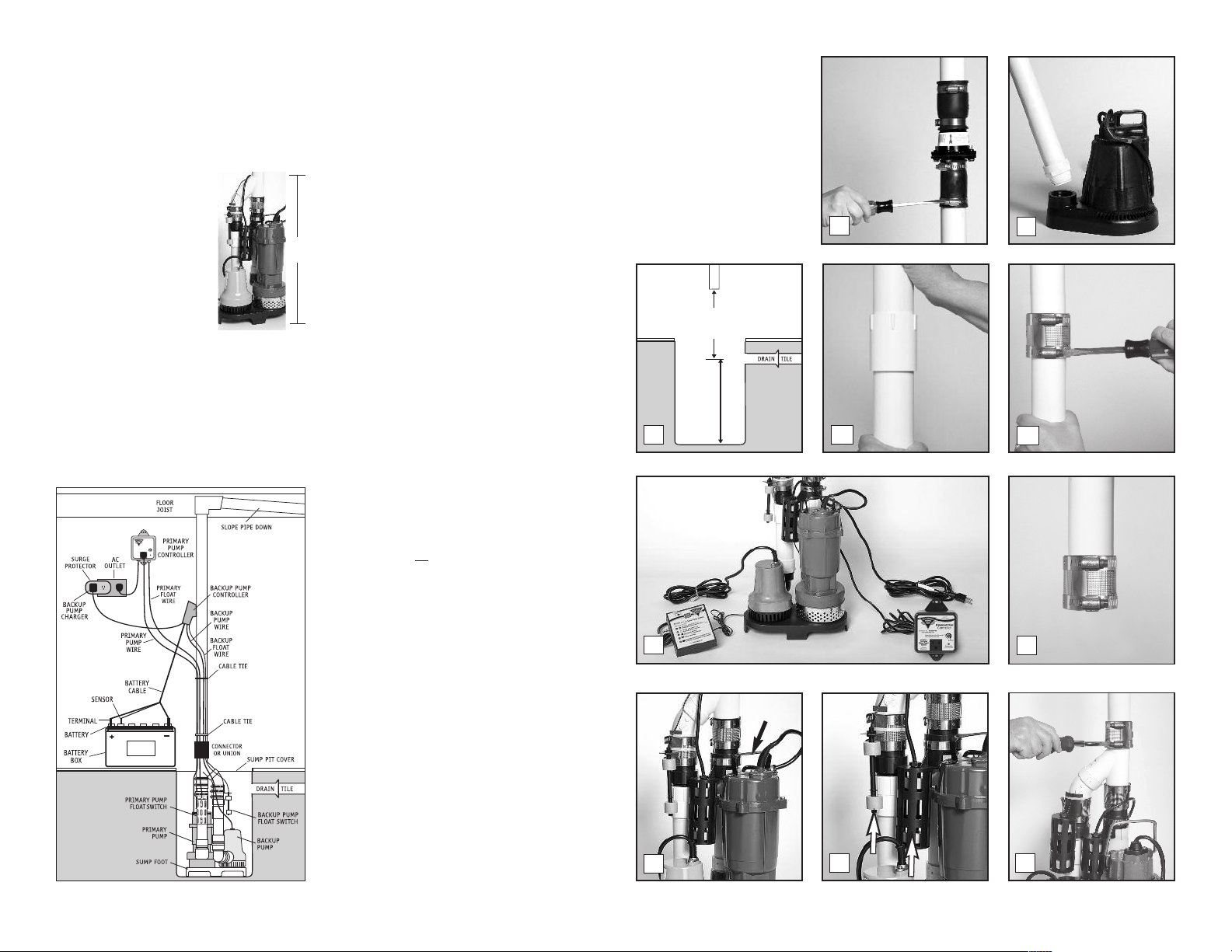
The Pro Series Pair of Pumps combination system
is compact and will fit in a sump pit as small as
12” wide. It measures 23¾” inches from the
bottom of the pump stand to the top of the Yconnector where it will be attached to the
discharge pipe.
Use a pit that conforms to all
local codes, and check the
code to see if a gate valve or
ball valve if is required.
The path of the existing
vertical discharge pipe to an
exterior wall should have the
shortest path with the fewest
turns. The more turns will reduce the pumping
capacity. The horizontal discharge pipe must be
positioned in a downward slope when it exits the
building, so any remaining water will drain away.
Failure to do this will prevent water from exiting
the pit, and damage the pump if the line freezes.
(see Diagram A)
The system should be placed on a flat surface free
Diagram A
Page 3
233/4“
from dirt and debris. If the bottom of the sump
pit is not clean, remove as much of the debris as
possible. The pumps are attached to a sump foot
(stand) to raise them above any debris.
If you are replacing an old sump pump, unplug
the pump from the outlet.
1. Remove the check valve or rubber union.
Discard the check valve. The Pro Series
system contains built-in check valves, so
the old check valve will not be needed. If
the existing system is installed without a
check valve or rubber union, saw the pipe
apart above the sump pit. (Refer to the
diagram in step 3)
2. Remove the old pump from the pit, and
unscrew the pipe and pipe adapter from the
pump. You can use this pipe for the rest of
the installation.
3. Measure the distance from the bottom of the
sump pit to the end of the discharge pipe.
Subtract 24¾” inches (the height of the pump
system + 1 inch). Cut a piece of 1-1/2” rigid
PVC pipe to that length.
4. (a) Connect this piece to the discharge pipe
by cementing the two pieces together with a
1-1/2” PVC pipe connector. (Follow the
instructions on the PVC pipe cleaner and
cement.) OR
, (b) connect the two pieces of
pipe together with a no hub coupling.
5. Remove the attached cords and controllers
from the carton and place them next to the
pump system. BE SURE THE CORDS AND
CONTROLLERS DO NOT FALL INTO THE SUMP PIT.
6. Loosen the hose clamps on the no hub
coupling and slide the coupling up on the
discharge pipe. Tighten the upper hose clamp.
7. Lift the combination system by the handle on
the primary pump and lower it into the sump
pit. Make sure it is level.
8. Inspect the two float switches. They should
both be vertical.
9. Inspect all of the screws on the hose clamps
of the no hub couplings (primary and backup
pumps). They should be tight.
10. Position the top of the pump system pipe so
that it is directly below the
discharge pipe. Connect the
system with the no hub coupling,
and tighten the upper and lower
hose clamps. Make sure both the
discharge pipe and the system
have ample overlap within the
no hub coupling.
5
LIFT
7
1
4a3
8 9
2
4b
6
Page 5
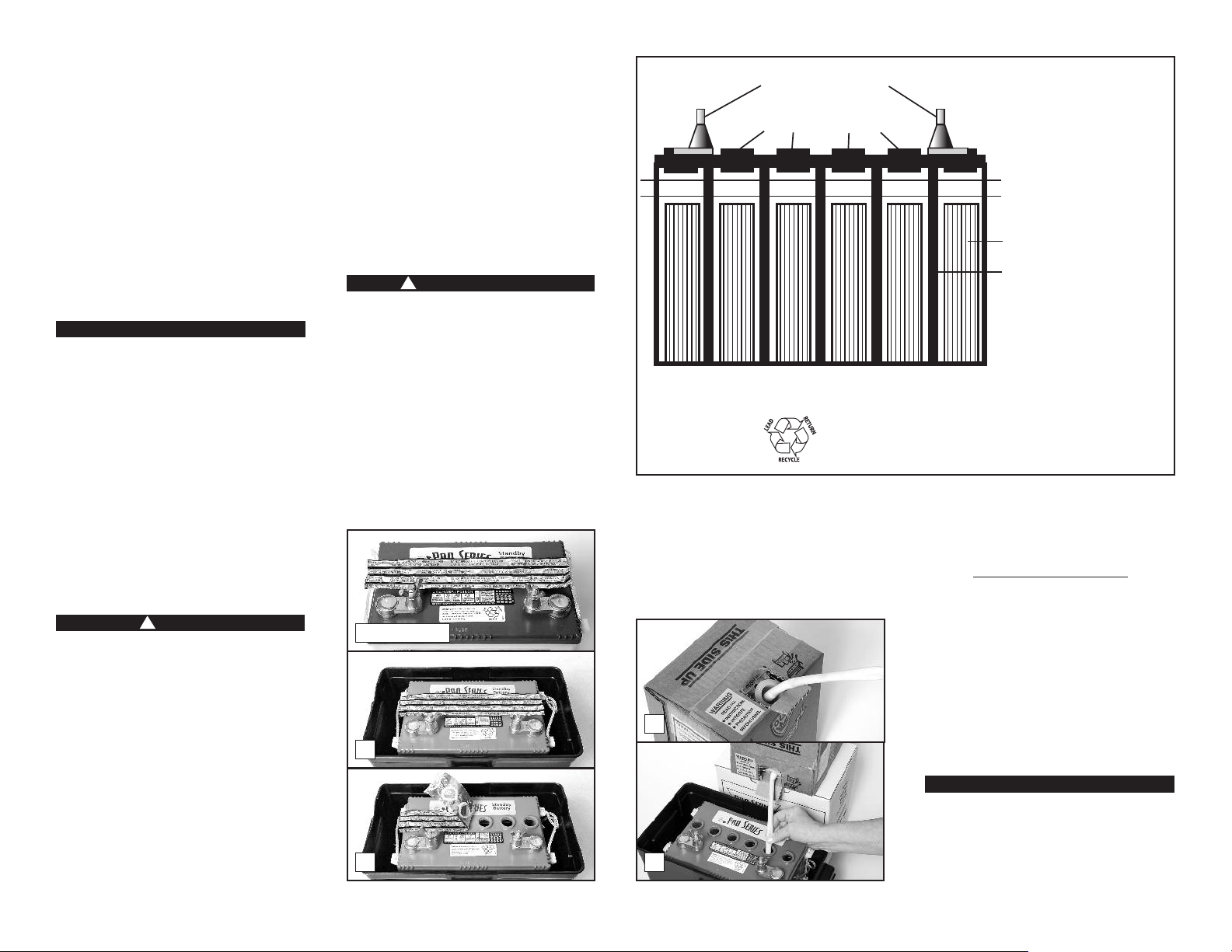
Battery Instructions
2nd LEVEL
1st LEVEL
P
LATES
CE LL WAL L
BATTERY TERMINALS
BATTERY CAP RINGS
CROSS SECTION OF BATTERY
The PHCC Pro Series B-1000 Standby Battery has
been designed to run this system for a minimum
of 50 hours, based on a 10% duty cycle.
However, most of the time the pump will turn on
and off, and the battery will run the pump
intermittently for days. In addition, the unique
materials in the battery enable it to last longer
in standby service. The PHCC-1000 battery
backup system will also accommodate the PHCC
Pro Series B12-90 maintenance free (AGM)
battery. To extend the run time of the pump, use
the PHCC Pro Series B-2200 Standby Battery or
B12-90 maintenance free (AGM) battery.
Note: The battery will not run the primary pump.
CAUTION
• The use of automotive batteries is NOT
recommended. Automotive batteries are
not designed for this application. They will
only run the pump for a short time and will
have a shorter life than a standby battery.
• The battery fluid sensor is designed to fit
the Pro Series Standby batteries. Measuring
the battery fluid is one of the most
important features of the system, since
about 80% of backup sump pump failures
are the result of a battery that has dried out.
• The internal construction of some batteries
may not be compatible with this system.
Glentronics, Inc. can not guarantee the
compatibility of other brands of batteries.
The use of a PHCC Pro Series battery is
HIGHLY recommended.
DANGER
!
DO NOT insert the fluid sensor into any
battery except a PHCC Pro Series battery (B1000 or B-2200). DO NOT use the enclosed
battery cap on any battery except a PHCC Pro
Series B-1000 or B-2200 battery. DO NOT drill
a hole in the cap or the top of another brand
of battery to accommodate the fluid sensor.
Batteries emit explosive gases, which can
cause serious injury or death.
PREPARING THE PRO SERIES STANDBY BATTERY
The Pro Series Standby batteries are shipped dry
(without acid) so they never lose power before
you take them home. A battery is activated
when the acid is added, and then it slowly
begins to deteriorate as it ages. By adding the
acid just before use, the battery will always be
fresh. Use 1.265 specific gravity battery acid to
fill the battery. It is available where you
purchased the battery.
NOTE: Pro Series batteries now come in two
configurations. The tops of the batteries look
different, and the directions for filling the
batteries and connecting the fluid sensor will vary
slightly. Instructions for both batteries follow. If
the top of your battery looks like the photo of
BATTERY A, follow the instructions on this page.
If the top of your battery looks like the photo of
BATTERY B, follow the instructions on page 5.
DANGER/POISON
!
Contains sulfuric acid. Wear eye and clothing
protection. If battery acid contacts skin or
clothing, wash immediately with soap and
water. If acid enters eyes, flush with water for
15 minutes, and get prompt medical attention.
Review the safety instructions on page 1.
TO FILL THE BATTERY
1. Place the battery box on the floor. Place the
dry (unfilled) battery into the battery box.
2. Remove the foil seal on the top of the battery.
3. Carefully push in the perforated tab at the top
of the acid pack. Lift up the large tab and
pull out the dispensing hose. Hold the hose
BATTERY A
1
2
DO NOT throw an old battery in
the trash. Take it to a service
station or recycling center.
upright above the pack and squeeze the hose
forcing all the acid back into the pack.
4. Position the acid pack and battery as shown
below. Pinch the end of the hose together
and cut off the tip. Insert the end of the hose
into each cell. Control the flow by pinching
3
4
Diagram B
1. Fill to 1st level,
cover the plates
2. Then fill to 2nd
level, just below
the bottom of the
cap rings
the hose with thumb and forefinger. Fill each
cell of the battery to a level just covering
the battery plates, and then go back and
top off each cell equally. It is important to
have all the cells filled equally
battery will not operate properly. The acid
should reach a level about ¼” below the cap
ring as shown in the diagram above. DO NOT
OVERFILL THE BATTERY. (Diagram B)
A newly filled battery will sometimes require
additional acid after about 20 minutes. Reexamine the fill level, and add additional acid if
necessary. The battery acid may bubble at this
time and give off a sulfur-like smell, but this is
normal. After the battery has been filled, screw
the caps securely on the top of the battery.
CAUTION
When you fill the battery for the FIRST time,
it will be the ONLY time you add acid to the
battery. In the future, when the fluid level is
low, add distilled water to the cells. NEVER
add more acid.
or the
Page 4
Page 6
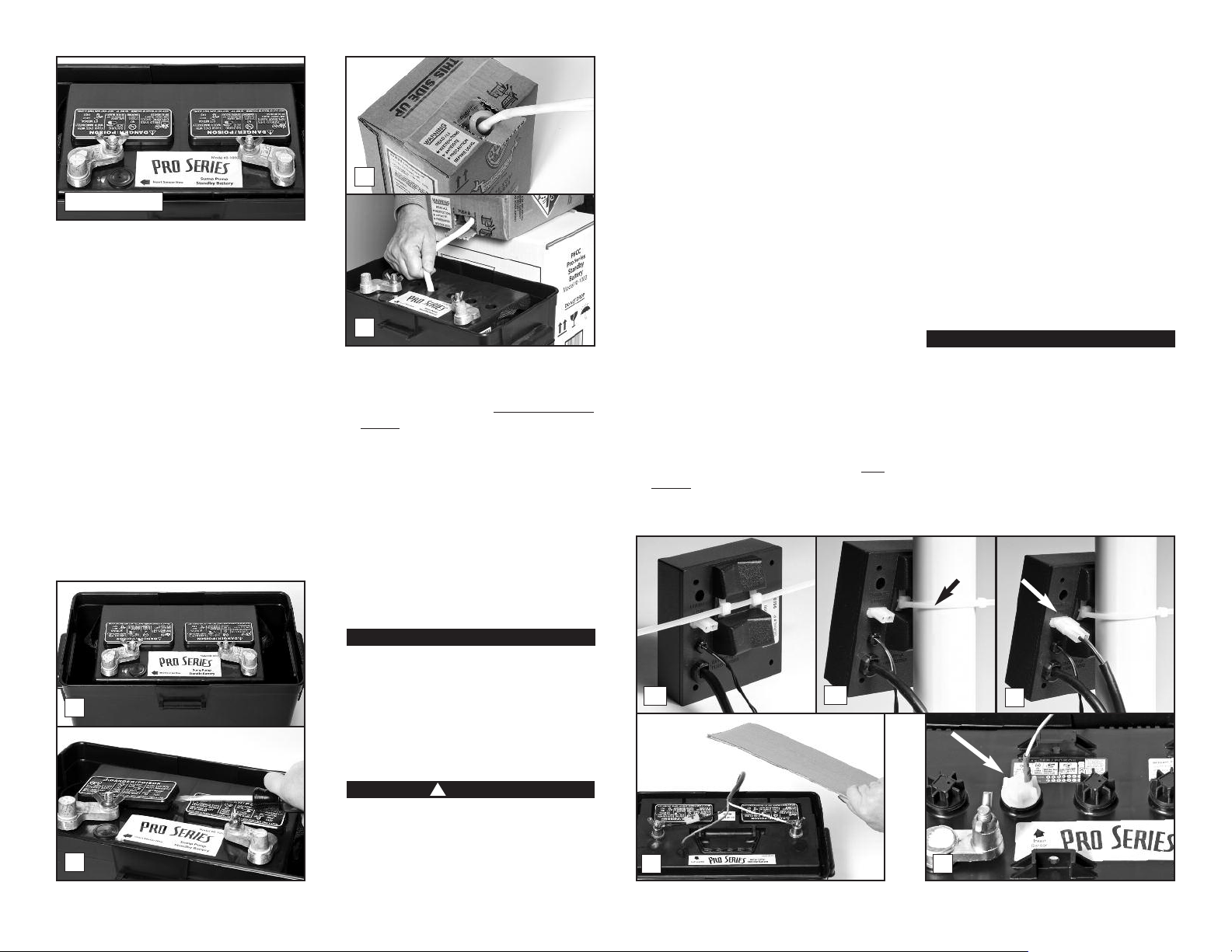
BATTERY B
If your battery looks like the battery above,
follow these directions.
1. Place the battery box on the floor. Place the
dry (unfilled) battery into the battery box.
2. Remove the two battery caps by lifting them
up with a screwdriver. DO NOT lift the cap by
prying it up from the groove on the back of
the cap. It may damage the vent.
3. Carefully push in the perforated tab at the top
of the acid pack. Lift up the large tab and
pull out the dispensing hose. Hold the hose
upright above the pack and squeeze the hose
forcing all the acid back into the pack.
4. Position the acid pack and battery as shown
at the right. Pinch the end of the hose
together and cut off the tip. Insert the end
of the hose into each cell. Control the flow
by pinching the hose with thumb and
forefinger. Fill each cell of the battery to a
3
4
level just covering the battery plates, and
then go back and top off each cell equally.
It is important to have all the cells filled
equally or the battery will not operate
properly. The acid should reach a level about
¼” below the cap ring as shown in Diagram B
on the previous page. DO NOT OVERFILL THE
BATTERY. (See diagram B)
A newly filled battery will sometimes require
additional acid after about 20 minutes. Reexamine the fill level, and add additional acid if
necessary. The battery acid may bubble at this
time and give off a sulfur-like smell, but this is
normal. After the battery has been filled, press
the caps securely on the top of the battery.
tools on the battery. If battery acid contacts
eyes, flush with water for 15 minutes. Review
the safety instructions on page 1.
When you position the control unit on the
discharge pipe, be sure the charger cord will
reach the AC power outlet, and the pump cable
and the float switch will reach the bottom of the
sump. Position the unit in a well-ventilated
area. Do not place anything on top of the
battery. (Diagram C, page 6)
1. Mounting the control unit: (a) Thread one
plastic wire tie through the two mounting
brackets on the back of the control unit. (b)
Secure the controller to the discharge pipe of
the Pro Series pumps by wrapping the tie
around the pipe and pulling it tight.
2. Connecting the backup pump: Remove the
security tag from the pump and plug the
pump wires into the pump connector on the
back of the control unit.
3. Installing the battery fluid sensor: Remove
the cover of the battery box by pushing in the
tabs on the front and back, then lifting up.
Fan the area around the top of the battery
with a piece of cardboard (or another nonmetallic material) to remove any hydrogen or
oxygen gas that may have been emitted from
the battery.
4. If you are using BATTERY A, replace the
battery cap that is 2nd from the POSITIVE (+)
post with the battery cap that is provided in
the Pro Series package. An arrow on the top
of the battery marks this position. There are
two holes in the battery cap. Insert the fluid
sensor in the hole that is off-center on the
top of the cap. Do not glue the sensor into
the cap.
5. If you have BATTERY B, a hole has been
molded into the top of the battery to accept
the fluid sensor rod. The sensor hole is
marked by the label on top of the battery.
Hold the sensor straight and press it firmly
into the hole all the way up to the connector.
Do not bend the sensor rod.
CAUTION
6. If you are not using the PHCC Pro Series
Standby battery, you cannot use the
battery fluid sensor. However, you must
attach the sensor to the POSITIVE (+) post
of the battery or the alarm will sound
continuously. The PHCC Pro Series sump
pump system will not warn you if the fluid
level is low in this configuration. You will
need to check your battery every couple of
months to see if it needs water. If the
1
2
Page 5
CAUTION
When you fill the battery for the FIRST time,
it will be the ONLY time you add acid to the
battery. In the future, when the fluid level is
low, add distilled water to the cells. NEVER
add more acid.
System Connections
DANGER
!
Risk of electrical shock or battery explosion,
which can cause serious injury or death. Wear
eye protection. Work in a well-ventilated area.
Do not smoke or allow a spark or flame in the
vicinity of the battery. Avoid dropping metal
1a
3
1b
2
4
Page 7

battery dries out, the system will not work.
Glentronics, Inc. 800.991.0466
www.stopflooding.com
Power On
(when flashing)
12 Amps
Maximum
10
45
Enhanced Float
Controller
Consider a Pro Series
Battery Backup
Sump Pump System
Adjust pump timer from 5-45 seconds
using a flat head screw driver.
Seconds
If you are using a maintenance-free
battery, you cannot add fluid to the
battery. The sensor must be attached to the
POSITIVE (+) post of the maintenance-free
battery to disconnect the fluid alarm.
7. Connecting the battery: Remove the wing
nuts from the battery terminals. Remove the
security tag from the battery cables. Attach
the battery cables to the battery…the WHITE
wire to the NEGATIVE (-) post, and the BLACK
wire to the POSITIVE (+) post. Replace the
wing nuts and tighten them.
8. Connecting the charger: Immediately plug
the charger into the charger hole on the back
of the control unit, then into an AC outlet on
the wall. (You should provide additional
protection for the control unit by using a
surge protector.)
9. If any of the alarms are sounding, press the
5
RED button on the front of the control panel
to silence them.
10. Secure the cover on the battery box by
slipping the tabs through the fittings on the
front and back of the box.
11. Connecting the primary pump: Mount the
controller to the wall through the 2 holes on
the cabinet using proper mounting hardware
for the application. The controller should be
mounted at least 4’ from the floor and 1’
from the outlet. Plug the controller into a
properly grounded 3-prong outlet. Then plug
the primary pump into the receptacle on the
controller. Check to ensure the float switch
wire is properly secured to the controller.
The float switch wire includes a connector
that can be separated from the controller
when the wire needs to be threaded through
small openings. The float switch connector
has a safety locking pin. This pin will
8a
8b
prevent the float switch from accidentally
being disconnected from the controller. To
remove the pin, push the pointed end of the
pin into the float connector and pull it out
from the other end. The float switch wire can
now be disconnected. Make sure to reinstall
the pin after the float switch is reconnected.
Using a flathead screwdriver, adjust the dial
on the front of the controller to select the
number of seconds that the primary pump
will run after the float drops. The dial can be
adjusted from 5-45 seconds. The
manufacturer default is about 10 seconds.
12. For a neater installation, secure the cables
from the controllers to the discharge pipe in
a couple places with additional cable ties.
Make sure the wires are not touching each
other or overlapping each other.
13. After the initial installation, be sure to check
the pump operation by filling the sump with
water and observing the pump through one
full cycle. The primary pump should run for
10 seconds after the lower float drops.
Diagram C
14. A pit cover is recommended for all
installations as a safety measure, and to
prevent debris from falling into the pit.
Place the cover on top of the pit making sure
not to pinch or crimp the pump wires with
the cover. The pit cover usually has an
existing hole that will allow the cords to be
passed through it, or you can drill a hole in
the cover.
Battery Maintenance
Measuring the battery fluid level is one of the
most important features of the system. It is
important to check the battery fluid levels at least
once every 4-6 months. Detailed instructions on
adding distilled water to the battery can be found
within the Understanding the Warnings &
Alarms section of this manual (page 7,
fluid in the battery is low). If you are not using
a PHCC Pro Series standby battery, you cannot use
the battery fluid sensor. You will need to attach
the fluid sensor to the POSITIVE (+) post of the
battery or the alarm will sound continuously. The
system will NOT warn you if the fluid level is low
in this configuration. You will need to check your
battery every couple of months to see if it needs
water. If the battery dries out, the system will not
work. If you are using a maintenance free battery
or sealed AGM battery you will also need to attach
the fluid sensor to the POSITIVE (+) post of the
battery or the or the alarm will sound
continuously.
2
The
6
POSITIVE
7
POST
NEGATIVE
POST
9
11 12
Product Operation
The dual float switch on the primary pump
contains two large floating rings enclosed within
a protective cage. Water will lift the bottom
float by ¼”, which will activate the pump. If for
any reason the lower float does not activate the
pump, the water will rise to the second float,
and it will activate the pump. As the pump
evacuates the water from the pit, the floats will
drop. The pump will run for an additional 10
seconds to extend the cycle after the lower float
drops. The blue controller for the primary pump
powers this switch.
During a power outage, or if more water is
entering the sump than the primary pump can
handle, the backup pump will automatically
begin pumping. It also has a dual float switch,
so if one float fails to activate the pump, the
Page 6
Page 8
second float will activate the pump as soon as
the water reaches that level. As the water
recedes below the float switch, a timer in the
control unit will run the pump an additional 45
seconds to empty the pit.
While the pumps are active, water will come
out of the 1/8” hole that is drilled in the pipe
above the pump. This is normal. The hole is
needed to prevent an air lock within the
system. Do not obstruct this hole or an air
lock may prevent the pump from activating,
and the basement will flood.
Batteries and sump pumps need maintenance.
The control unit on the backup system monitors
the battery and power conditions, and sounds an
alarm when maintenance is required. Following
is an explanation of the warnings and alarms.
Understanding the
Warnings & Alarms
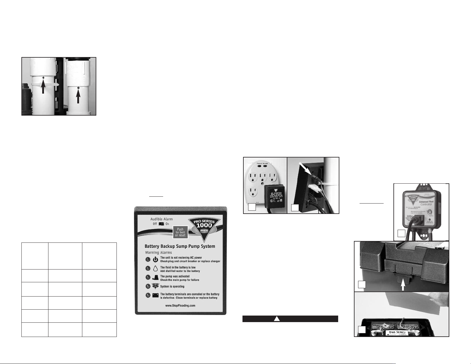
The Pro Series backup pump control unit features
a series of warning lights that pinpoint potential
Alarm can be Alarm shuts off
silenced before automatically
Warning corrected is corrected
Power
problem
Fluid level
is low
Pump was
activated RED button
System is
operating
Battery
problem
problem is when problem
Yes Yes
No Yes
Yes
No alarm No alarm
No Yes
No, push the
problems. In addition, an alarm sounds to alert
you to the problem. In some cases the lights
and alarm will go off automatically when the
problem has been solved. In others, the RED
button on the front of the control unit must be
pushed to silence the alarm. Refer to the table
below for a quick review of the features and their
corresponding alarm status.
SILENCING THE ALARM
DURING AN EMERGENCY
The Pro Series backup pump control unit is
equipped with a switch that will silence the
audible alarm during an extended emergency.
The “AC power”
be silenced during a power outage or during
heavy rains when the pump is activated
repeatedly.
To silence both the “AC power” and “Pump”
alarms, slide the “Audible Alarm” switch to OFF.
The “AC power” and/or the “Pump” light will
remain on, but the audible alarm will not sound.
When the emergency has ended, slide the
switch to the ON position to resume the full
monitoring capability, or you will not be
warned the next time an emergency occurs.
The “Fluid level”
alarms cannot be silenced. Both require
immediate attention.
1
and “Pump” 3alarms can
2
‚ and “Battery problem”
5
6
1
2
3
4
5
1
The unit is not receiving AC power
There are several causes for power failure. The
most common is a power outage by your electric
company. During this emergency, the Pro Series
system will automatically switch to battery
power and protect your basement from flooding.
You can silence the “AC power” alarm by sliding
the ”Audible Alarm” switch to OFF. The alarm
will be silenced, but the light will stay on. The
system will continue to operate while the power
alarm is silenced. Be sure to slide the switch
to the ON position when the power is restored
to resume full monitoring capability.
1. If the power is on in the rest of the house,
check the home circuit breaker or fuse box for
failure, and correct the problem.
2. Check the charger. Make sure it is securely
plugged into the wall outlet. Make sure the
outlet is working.
3. Check the charger plug that fits into the rear
panel of the control unit. Make sure it is
securely plugged into the control unit.
2
The control unit must receive 115 volts AC +/5% from the AC outlet. Any voltage lower than
110 volts will activate the “AC power” alarm.
Lower voltages can be caused by utility company
brown outs or a heavy power draw from other
appliances on the same circuit. Reduce the
number of appliances on the circuit.
If all the connections are secure and the wall
outlet is operating, but the “AC power” warning
light is still on, replace the charger unit with the
Pro Series part number 1015003. Contact
Glentronics at 800-991-0466 for parts.
2
The fluid in the battery is low
Risk of electrical shock or battery explosion,
which can cause serious injury or death. Wear
DANGER
!
3
eye protection. Work in a well-ventilated
area. Do not smoke or allow a spark or flame
in the vicinity of the battery. Avoid dropping
metal tools on the battery. If battery acid
contacts eyes, flush with water for 15
minutes and get prompt medical attention.
Review the safety instructions on page 1.
REFER TO THE PHOTOS BELOW
If this warning light and alarm are on, you need
to add distilled water to the battery. This alarm
cannot be silenced. When the battery is refilled
and the sensor is replaced, the alarm will go off
automatically. Battery fluid levels should be
checked every 4-6 months.
REFILLING THE BATTERY
1. Unplug the primary pump, and its blue
piggyback controller from the wall outlet.
Unplug the charger for the backup pump
control unit, too.
2. Remove the cover of the battery box by
pushing in the tabs on the front and back,
then lifting up.
3. Fan the area around the top of the battery
with a piece
of cardboard
(or another
non-metallic
material) to
remove any
hydrogen or
oxygen gas
that may
2
3
1
Page 7
Page 9
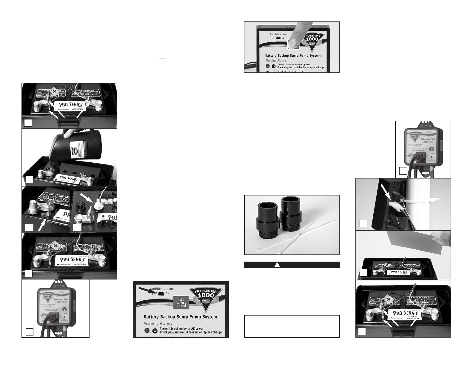
have been emitted from the battery.
4. Remove the fluid sensor from the top of the
battery, and then unscrew the wing nuts and
remove the battery cables from the battery.
5. Pry up the two battery caps, or unscrew the
six battery caps depending on the
configuration of your battery. Add distilled
water to the battery filler bottle and replace
the nozzle. Place the nozzle of the battery
4
5
6a
7
Remove
6b
filler into each cell of the battery and press
down. It will fill the battery cell to the
correct level and stop automatically. If
distilled water is not available, tap water with
a low mineral content may be used. Well
water is not
MORE ACID.
6. Replace the battery caps. Replace the fluid
sensor in the hole on the top of the battery,
or in the cap 2nd from the POSITIVE (+) post,
depending on the configuration of your
battery.
7. Replace the battery cables…the WHITE wire
to the NEGATIVE (-) post, and the BLACK wire
to the POSITIVE (+) post. Replace the wing
nuts and tighten.
8. Replace the cover on the battery box.
9. Plug the primary pump into the blue
piggyback controller, and plug both into the
wall outlet.
3
The pump was activated
When the water rises in the sump pit and
activates the float switch, the pump will begin
pumping, and the “Pump was activated” light
and alarm will turn on. The alarm stays on to
alert you to the fact that the standby system was
used to empty water from the sump. Try to
determine what caused the system to activate.
• Check the main AC pump for failure. It may not
be working, the float switch may be stuck, the
float switch wire may not be connected to the
main AC controller, or the pump may be too
small to handle the inflow of water.
• Make sure the discharge pipe is not clogged or
frozen.
• If the power was out, the backup pump was
automatically activated. You need to push the
RED button on the front of the control panel
to reset the alarm.
recommended. NEVER ADD
During a power outage or times when the pump is
activated repeatedly, you can temporarily silence
the alarm by sliding the “Audible Alarm” switch to
OFF. When the primary pump has resumed
normal operation, and the backup pump is no
longer activating repeatedly, slide the switch
to the ON position to resume the full
monitoring capability. The alarm and pump light
will still be on. Push the RED button on the front
of the control panel to silence the alarm.
REPLACING THE BACKUP PUMP
Before you begin this process, you will need a
new backup pump. You may also want to change
the check valves at this time. The check valves
have a 1½” MPT on one end, and a 1½” SLIP on
the other end. See page 15 for part numbers.
You will also need two (2) new wire ties.
DANGER
!
Risk of electrical shock or battery explosion,
which can cause serious injury or death. Wear
eye protection. Work in a well-ventilated
area. Do not smoke or allow a spark or flame
in the vicinity of the battery. Avoid dropping
metal tools on the battery. Review the safety
instructions on page 1.
1. Unplug the primary pump, and its blue
piggyback controller from the wall outlet.
Unplug the charger for the backup pump
control unit, too.
2. Unplug the backup pump from the back of the
black control unit.
3. Remove the cover of the battery box and fan
the area around the top of the battery with a
piece of cardboard (or another non-metallic
material) to remove any hydrogen or oxygen
gas that may have been emitted from the
battery.
4. Remove the sensor from the battery, and
remove the battery wires from the battery
terminals. Be sure they do not touch each
other while
one is
connected to
the battery.
1
2
3
YOU WILL BE DISCONNECTING ALL THE
WIRES. BE SURE THEY DO NOT FALL INTO
9
THE SUMP PIT.
4
Remove
Page 8
Page 10
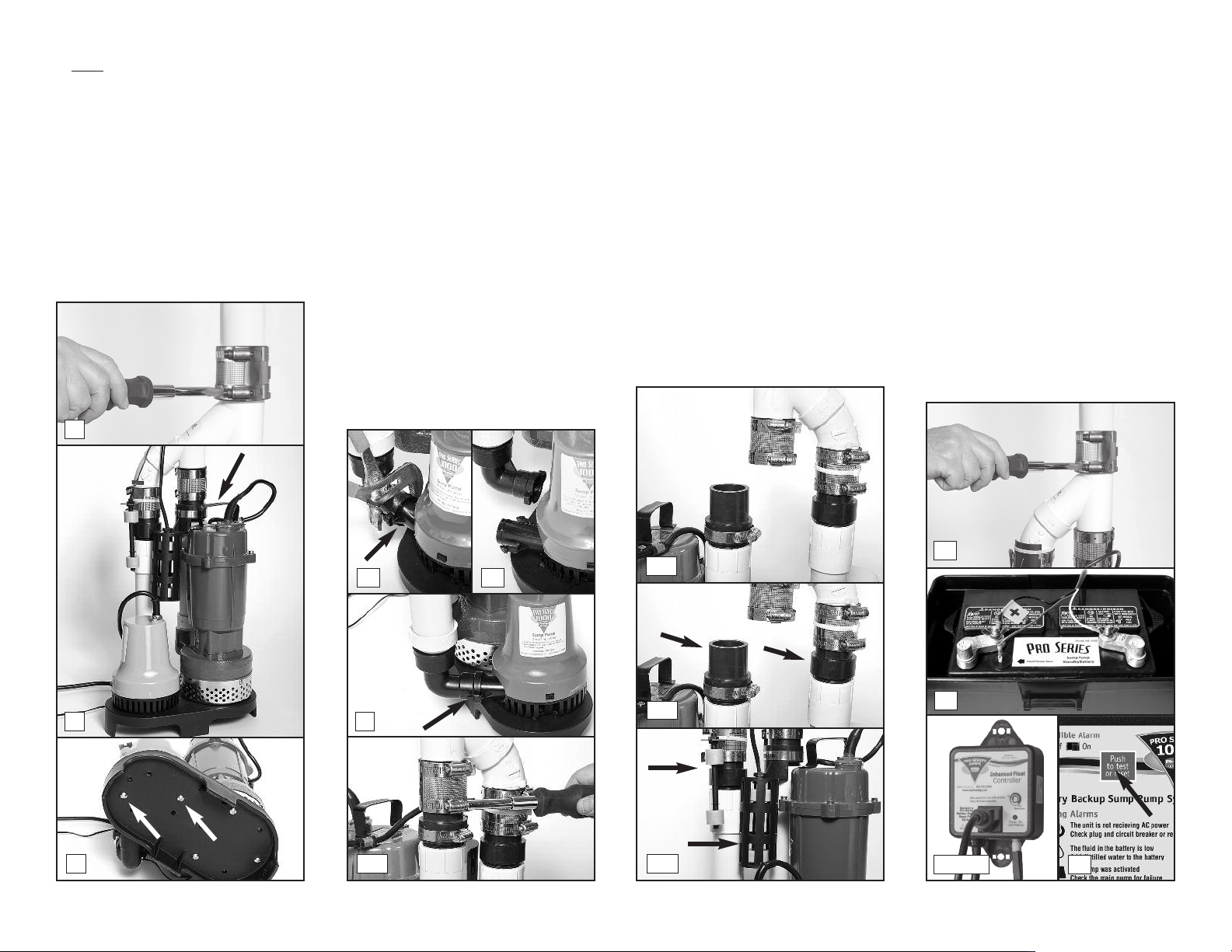
5. Slowly loosen the no hub coupling on the top
of the combination pump assembly to
separate the pipes. The water trapped in the
pipe will pour out into the sump as the no
hub coupling is loosened.
6. Separate the pump assembly from the no hub
coupling and lift it out of the sump pit by the
handle on the primary pump. Tip the
assembly over the sump pit to drain away any
remaining water.
7. Lay the pumps down and remove the two (2)
screws holding the backup pump to the sump
foot.
5
8. (a) Squeeze the clamps on the elbow of the
backup pump with a wrench to loosen them.
(b) Then squeeze the clamps together with
your fingers and pull the pump off of the
elbow.
9. Remove the elbow from the new pump. You
will not need it. Squeeze the clamps on the
pump elbow and insert the elbow into the
new pump.
10. Screw the base of the new backup pump into
the sump foot.
11. (OPTIONAL) While you have the pump out of
the sump pit, this would be a good time to
replace the check valves. A check valve with
1½” MPT on one end, and 1½” SLIP on the
other is commonly available, or you may
order this part #1141001 from Glentronics.
(a) You will need to loosen the screws on the
no hub couplings on both pipes. (b) Remove
the float switches. Then ease off the Yassembly. (c) The check valves can then be
unscrewed from the pipes and new valves can
be screwed into the pipes. (d) Replace the Yassembly and tighten the screws on the no
hub couplings. (e) Replace the float switches
making sure they are vertical with the float
for the primary pump lower than the float for
the backup pump. You will need to secure
them with a wire tie.
12. Lower the pumps into the sump pit by the
handle on the primary pump.
13. Ease the Y-assembly back into the no hub
coupling on the discharge pipe and tighten
the hose clamps.
14. Connect the backup pump to the back of the
black control unit.
15. Insert the fluid sensor into the top of the
battery, or into the battery cap, depending
on which battery you own.
16. Connect the battery wires to the battery
terminals, WHITE to the NEGATIVE (-) post,
and BLACK to the POSITIVE (+) post.
Replace the cover on the battery box.
17. Plug the charger from the black control unit
into the outlet. (You should provide added
protection for the control unit by using a
surge protector.)
18. Plug the primary pump into the blue
piggyback controller and then plug the
controller into the wall outlet. Check to
ensure the float switch wire is properly
secured to the controller.
19. If any of the alarms are sounding, press the
RED button for 1 second.
20. Fill the sump with water to make sure the
primary pump is working. When the
pumping cycle is finished, lift the float
switch on the backup pump to make sure it
activates the backup pump.
6
7
Page 9
8a
9
11a
8b
11b
11c
11e
13
16
1917 & 18
Page 11
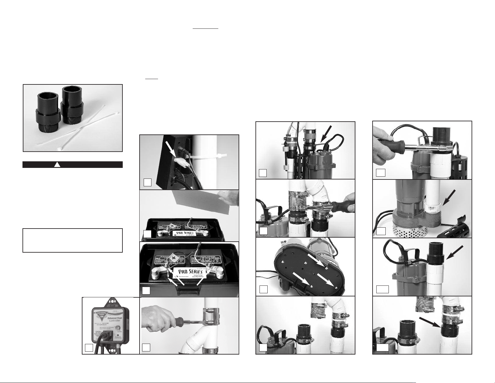
REPLACING THE PRIMARY PUMP
Before you begin this process, you will need a
new primary pump. You may also want to change
the check valves at this time. The check valves
have a 1½” MPT on one end, and a 1½” SLIP on
the other end. See page 15 for part numbers. You
will also need two (2) new wire ties.
DANGER
!
Risk of electrical shock or battery explosion,
which can cause serious injury or death. Wear
eye protection. Work in a well-ventilated
area. Do not smoke or allow a spark or flame
in the vicinity of the battery. Avoid dropping
metal tools on the battery. Review the safety
instructions on page 1.
cardboard (or another non-metallic
to remove any hydrogen or oxygen gas that
may have been emitted from the battery.
4. Remove the sensor from the battery; remove
the battery wires from the battery terminals.
Be sure they do not touch each other while
one is connected to the battery.
5. Slowly
6. Lift the pump assembly out of the pit by the
loosen the no hub coupling on the top
of the combination pump assembly to
separate the pipes. The water trapped in the
pipe will pour out into the sump as the no
hub coupling is loosened.
handle on the primary pump. Tip the
assembly over the sump pit to drain any
2
material)
remaining water.
7. Unscrew the no hub coupling on the pipe
connected to the primary pump.
8. Lay the pumps down and remove the three (3)
screws holding the primary pump to the sump
foot. Save these screws or replace them with
#14 x ¾” self-tapping stainless steel screws.
9. Ease the pump out of the no hub coupling.
10. Loosen the hose clamp holding the float
switch, cut the wire tie holding the switch,
and remove the switch from the pipe. Note
its position.
11. Unscrew the pipe and the adapter from the
6
primary pump, and screw it on to the new
pump.
12. (OPTIONAL) While you have the pump apart,
this would be a good time to replace the
check valves. A check valve with 1½”MPT
on one end, and 1½” SLIP on the other is
commonly available, or you may order this
part #1141001 from Glentronics. (a)
Unscrew the check valve on the primary
pump and screw in a new one. (b) To replace
the other check valve, remove the other no
hub coupling and the float switch and ease
the Y-assembly off of the pipe. Unscrew the
old check valve and screw in the new valve.
10
YOU WILL BE DISCONNECTING ALL THE
WIRES. BE SURE THEY DO NOT FALL INTO
THE SUMP PIT.
1. Unplug the primary pump, and its blue
piggyback controller from the wall outlet.
Unplug the charger for the backup pump
control unit, too.
2. Unplug the backup
pump from the back
of the black control
unit.
3. Remove the cover of
the battery box and
fan the area around
the top of the battery
with a piece of
1
3
4
5
Remove
7
8
9
11
12a
12b
Page 10
Page 12
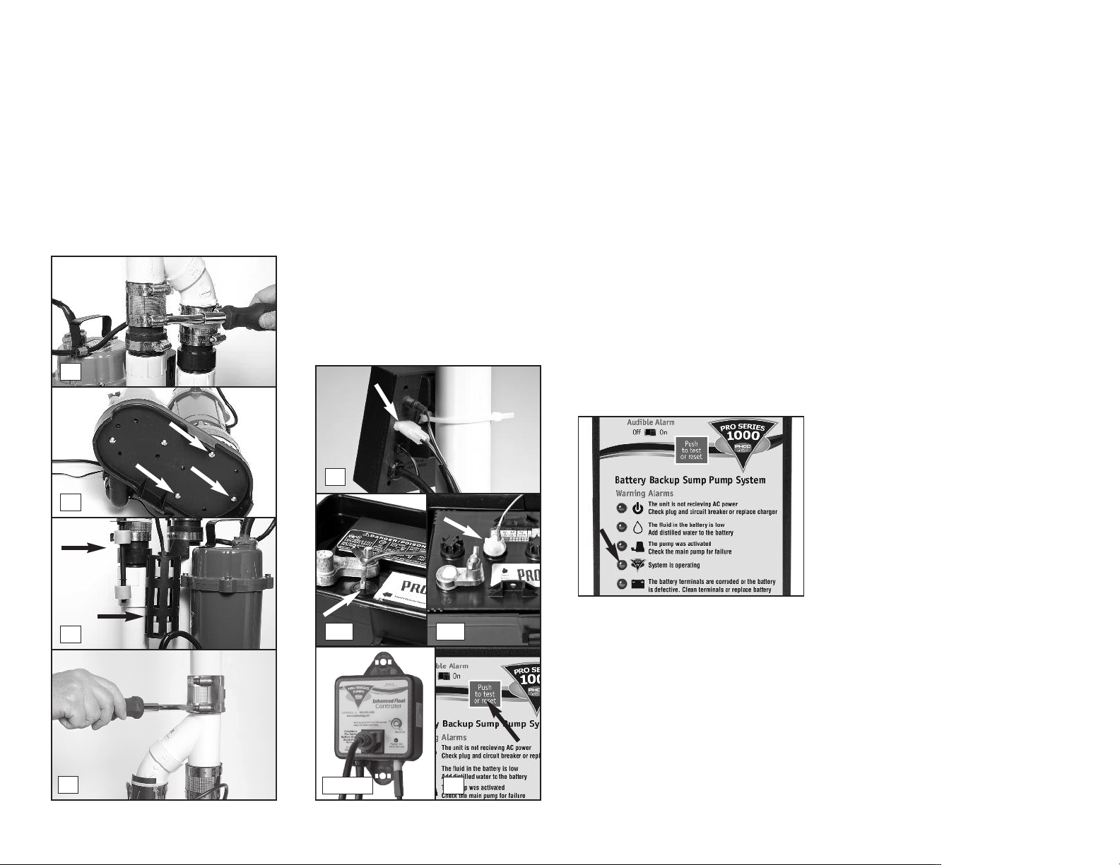
13. Reconnect the pipes to the Y-assembly and
line up the pipe on the primary pump
parallel to the pipe on the backup pump.
Tighten the no hub couplings.
14. The strainers on the pumps may vary slightly.
If the new strainer does not line up with the
holes on the sump foot, drill three holes
through the foot into the strainer in the
same positions where the screws were
before. Use a #4 or a 3/16” drill bit. Screw
the sump foot on to the pump with #14 x ¾”
self tapping stainless steel screws.
13
14
15
17
15. Replace the float switches making sure they
are vertical with the float for the primary
pump lower than the float for the backup
pump. You will need to secure them with a
wire tie.
16. Lower the pump back into the pit by the
handle of the primary pump.
17. Connect the top of the system to the no hub
coupling and tighten the hose clamp.
18. Connect the backup pump to the back of the
black control unit.
19. Insert the fluid sensor into the top of the
battery, or into the battery cap, depending
on which battery you own.
20. Connect the battery wires to the battery
terminals, WHITE to the NEGATIVE (-) post,
and BLACK to the POSITIVE (+) post.
Replace the cover on the battery box.
18
19a 19b
2321 & 22
21. Plug the charger from the black control unit
into the outlet. (You should provide added
protection for the control unit by using a
surge protector.)
22. Plug the primary pump into the blue
piggyback controller and then plug the
controller into the wall outlet. Check to
ensure the float switch wire is properly
secured to the controller.
23. If any of the alarms are sounding, press the
RED button for 1 second.
24. Fill the sump with water to make sure the
primary pump is working. When the
pumping cycle is finished, lift the float
switch on the backup pump to make sure it
activates the backup pump.
4
The system is operating
This green light should always be flashing. It
will flash when there is power coming from
either the battery or the AC outlet.
5
The battery terminals are corroded or
the battery is defective
This light and alarm will come on when the
control unit detects there is less than ½ hour of
pumping power left in the battery, or that the
battery is defective. The alarm cannot be
silenced, because action needs to be taken to
protect your basement. If your battery is more
than five (5) years old, replace it. If not, here
are several situations that would cause the pump
to run the battery for an extended time and
discharge the battery: Check the list below
before you replace the battery.
• If the top light on the controller is also on, it
means that the unit is not receiving AC power.
Either the AC power is out, the circuit breaker
has blown, or the outlet is bad. When the
problem is corrected, the battery should
recharge.
• If the third light on the controller is also on,
check your main pump for failure. The backup
pump may have been activated repeatedly if
your main AC pump is broken or you are
experiencing heavy rains and your main pump
cannot keep up with the inflow of water. You
may need to upgrade or replace your main
pump. When the problem is corrected, the
battery should recharge.
• If no other lights are on, this means the
terminals may be corroded, and the battery
cannot charge properly. Unplug the charger
from the wall outlet. Then, check the battery
cables and the battery terminals for corrosion.
Clean and tighten them as needed. The
procedure is described on page 12.
If the battery terminals have been cleaned and
the light is still on, there could be a problem
with the controller or the battery. The best way
to determine if the battery is the problem is to
have it charged and load tested at any local car
service station. If the battery is bad and less
than one (1) year old, it can be returned to the
place of purchase for a replacement (receipt
required). If the battery is good, contact
Glentronics’ service department for further
instructions. The phone number is 800-991-0466.
If the battery alarm goes on while the pump is
running and the power is out, you will have a
minimum of one-half (1/2) hour of continuous
pumping time to replace the battery. (In most
cases, the pump does not run continuously, and
therefore, you actually have a longer time to
replace it.) You will not be able to silence the
alarm. Left unattended, the basement will flood.
In a severe emergency, if a replacement battery
is not available, you could temporarily use your
car battery, or recharge this battery by
connecting it to your car battery. Once the AC
Page 11
Page 13
power is restored, the battery will recharge
automatically, unless it is old or damaged. The
alarm will turn off when the AC power is restored
and the pumping energy reaches one-half (½)
hour or more.
In the event that your Pro Series sump pump
system has pumped for an extended period of
time, the battery may be very depleted. In this
condition, when the AC power is returned to the
unit, a battery alarm will continue to sound. The
battery may need a longer period to recharge.
For a faster recharge, an automotive or marine
battery charger can be used to recharge the
battery. Follow the manufacturer’s instructions
and safety information included with the
charger.
WARNING
!
When another charger is used, first
disconnect the Pro Series charger from the
control unit, and then disconnect the control
unit from the battery. Using another charger
without disconnecting the control unit will
destroy the control unit and void the
warranty.
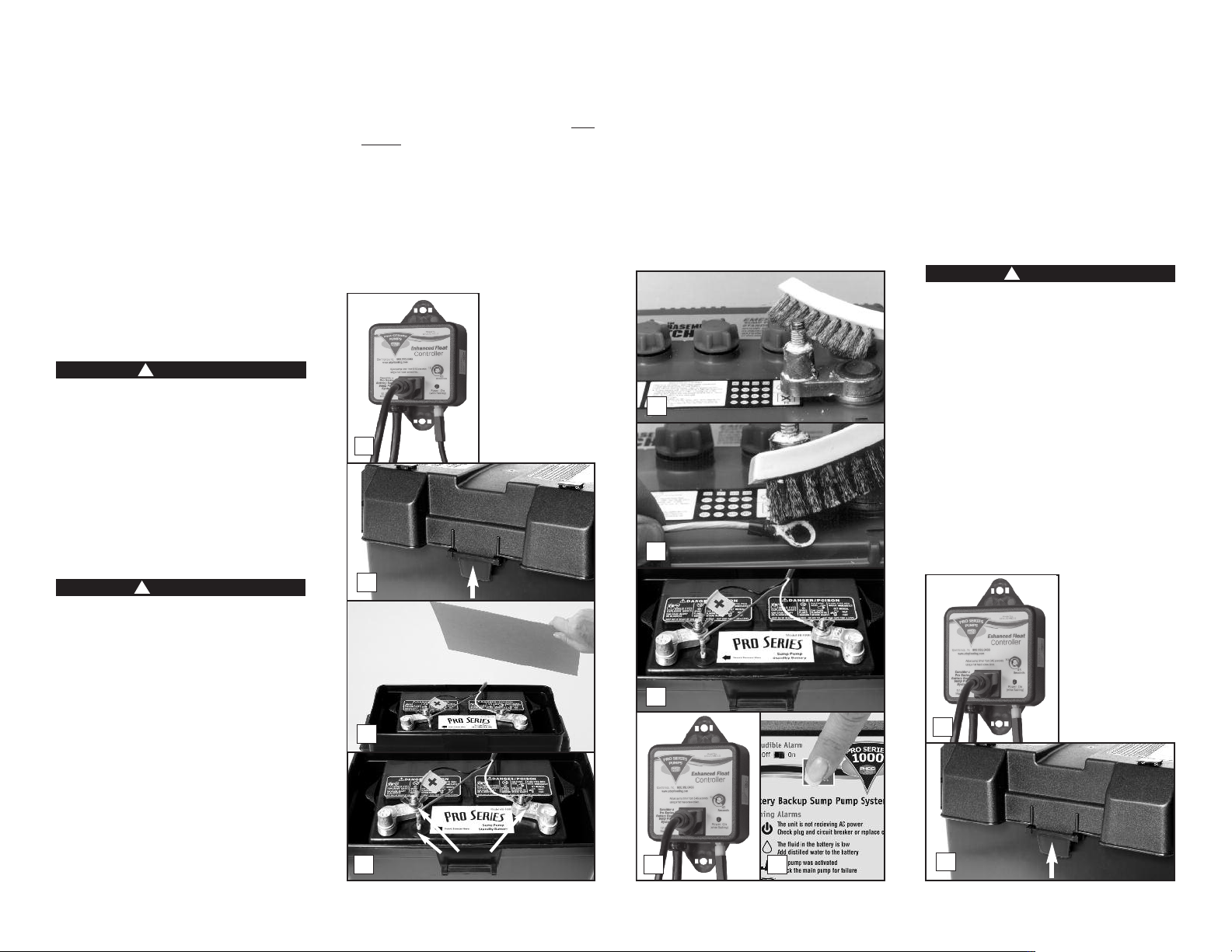
TO CLEAN THE BATTERY TERMINALS
AND CABLES
pushing in the tabs on the front and back,
then lifting up.
3. Fan the area around the top of the battery
with a piece of cardboard (or another nonmetallic material) to remove any hydrogen or
oxygen gas that may have been emitted from
the battery.
4. Remove the fluid sensor from the top of the
battery. Unscrew the wing nuts. Remove the
battery cables.
5. Clean the battery posts with a battery
terminal cleaner or a wire brush.
1
6. Clean any corrosion off of the ring connectors
on the ends of the battery wires. Use a stiff
brush or sandpaper. DO NOT apply corrosion
resisting sprays or pads to the terminal rings
or posts after you have cleaned them, since
this could prevent the system from charging
properly.
7. Replace the fluid sensor in the top of the
battery. Then replace the battery cables,
WHITE to the NEGATIVE (-) post and BLACK to
the POSITIVE (+) post. Tighten the wing
5
6
nuts. Replace the cover on the battery box.
8. Plug the primary pump into the blue
piggyback controller and then plug the
controller into the wall outlet. Check to
ensure the float switch wire is properly
secured to the controller.
9. If any of the alarms are sounding, press the
RED button on the front of the control panel
for one (1) second.
REPLACING THE BATTERY
DANGER
!
Risk of electrical shock or battery explosion,
which can cause serious injury or death. Wear
eye protection. Work in a well-ventilated
area. Do not smoke or allow a spark or flame
in the vicinity of the battery. Avoid dropping
metal tools on the battery. If battery acid
contacts eyes, flush with water for 15
minutes and get prompt medical attention.
Review the safety instructions on page 1.
REFER TO THE PHOTOS BELOW AND ON PAGE 13
1. Unplug the primary pump, and its blue
piggyback controller from the wall outlet.
Unplug the charger for the backup pump
control unit, too.
DANGER
!
Risk of electrical shock or battery explosion,
which can cause serious injury or death. Wear
eye protection. Work in a well-ventilated
area. Do not smoke or allow a spark or flame
in the vicinity of the battery. Avoid dropping
metal tools on the battery. If battery acid
contacts eyes, flush with water for 15
minutes and get prompt medical attention.
Review the safety instructions on page 1.
REFER TO THE PHOTOS AT RIGHT
1. Unplug the primary pump, and its blue
piggyback controller from the wall outlet.
Unplug the charger for the backup pump
control unit, too.
2. Remove the cover of the battery box by
2
7
3
4
Remove
8 9
1
2
Page 12
Page 14
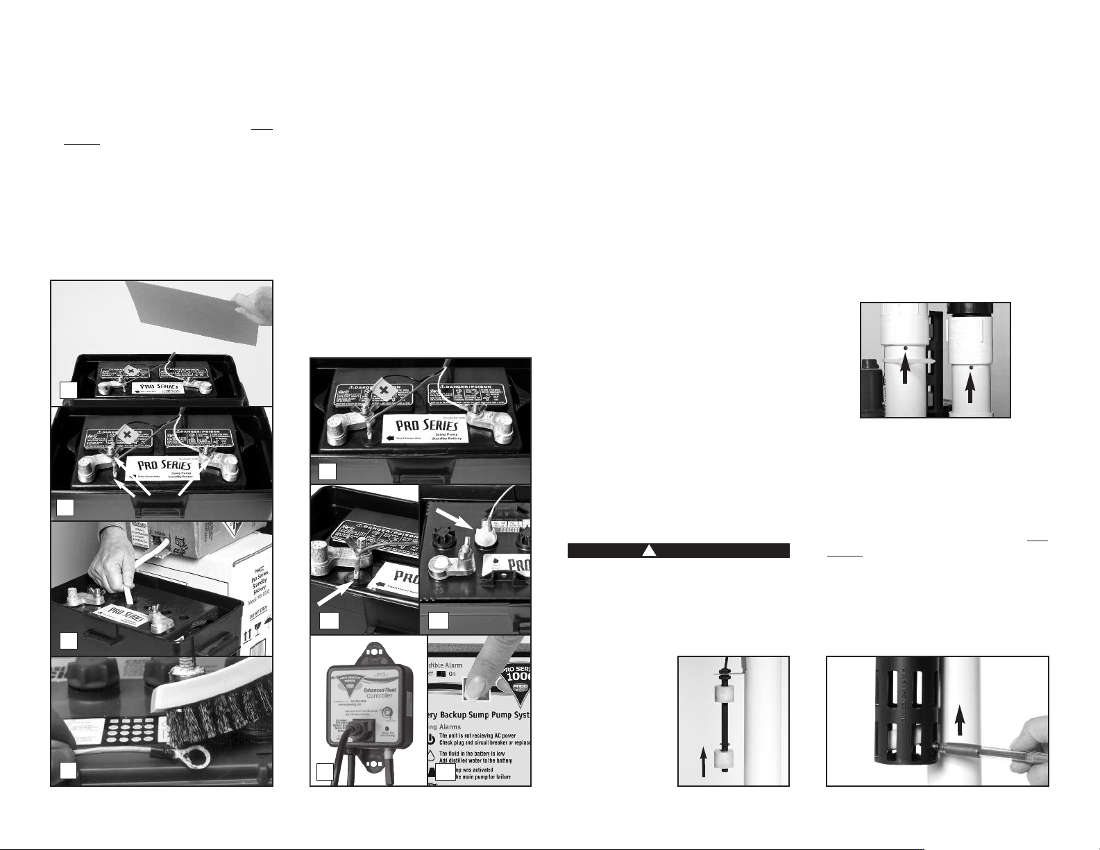
2. Remove the cover of the battery box by
pushing in the tabs on the front and back,
then lifting up.
3. Fan the area around the top of the battery
with a piece of cardboard (or another nonmetallic material) to remove any hydrogen or
oxygen gas that may have been emitted from
the battery.
4. Remove the fluid sensor from the top of the
battery. Unscrew the wing nuts and remove
the battery cables.
5. Remove the old battery from the battery box
and place the new battery in the box. Fill the
3
4
5
6
Remove
battery following the instructions on page 4
or 5.
6. Clean any corrosion off of the ring connectors
on the ends of the battery wires. Use a stiff
brush or sandpaper. DO NOT apply corrosion
resisting sprays or pads to the terminal rings
or posts after you have cleaned them, since
this could prevent the battery from charging
properly.
7. Replace the battery cables, WHITE to the
NEGATIVE (-) post and BLACK to the POSITIVE
(+) post. Tighten the wing nuts.
8. Insert the fluid sensor in the top of the
battery, or in the cap 2nd from the POSITIVE
(+) post, depending on the configuration of
your battery. Replace the cover on the
battery box.
7
8a 8b
109
9. Plug the primary pump into the blue
piggyback controller and then plug the
controller into the wall outlet. Check to
ensure the float switch wire is properly
secured to the controller.
10. If any of the alarms are sounding, press the
RED button on the front of the control panel
for one (1) second.
Test/reset button
6
The TEST button may be used to check the
backup pump and system. Push the TEST button.
This will activate the pump for as long as you
hold the button. It will stop as soon as you let
go of the button.
While the pump is active, water will come out of
the 1/8” hole that was drilled into the PVC
discharge pipe. This is normal. This hole is
needed to prevent an air lock within the system.
DO NOT obstruct the hole or an air lock may
prevent the system from activating.
If the “Pump was activated” alarm is sounding,
press the button for one (1) second to reset the
alarm.
TESTING THE FLOAT SWITCH FOR THE
BACKUP PUMP
It is important to manually test the float
switches periodically.
DANGER
!
Unplug the main AC pump when installing or
servicing the backup pump to avoid electric
shock. Failure to do so could cause serious
injury or death. Review the safety
instructions on page 1.
Lift the float up and
let go. This will
activate the pump.
The control unit will
run the pump for
approximately 45
seconds so it can
empty all the water
in the sump pit. If
there is no water in
Lift
Float
the pit, the pump can run dry for this amount of
time. The alarm will sound and the “Pump was
activated” light will go on. After the pump has
stopped, push the RED button to silence the
alarm. If the RED button is pressed before the
pump has stopped, the alarm will go off
temporarily. Wait for the pump to stop pumping,
and then push the RED button on the front of
the control unit to completely silence the alarm.
While the pumps are active, water will come out
of the 1/8” hole that is drilled in the pipe above
the pump. This is normal. The hole is needed to
prevent an air lock within the system. DO NOT
obstruct this hole or an air lock may prevent the
pump from activating, and the basement will
flood.
BE SURE TO PLUG IN THE MAIN AC PUMP WHEN
YOU HAVE COMPLETED THE TEST.
TESTING THE FLOAT SWITCH FOR THE
PRIMARY PUMP
Lift the float up with a pencil, or another nonmetallic item, and let it go to activate the pump.
The pump will run an additional 10 seconds after
the float returns to the original position. It will
not damage the pump to run it for this short
time if the sump pit is dry. However, do not hold
the float up for an extended time without water
in the sump pit.
Lift
Float
Page 13
Page 15

While the pumps are active, water will come out
of the 1/8” hole that is drilled in the pipe above
the pump. This is normal. The hole is needed to
prevent an air lock within the system. DO NOT
obstruct this hole or an air lock may prevent the
pump from activating, and the basement will
flood.
MAINTENANCE CHECK LIST
Maintenance should be performed 1-2 times
per year
1. Lift the float switch on both pumps as
described at above.
2. Remove all debris from the bottom of the pit
and pump strainer.
3. Remove all debris from the water.
4. Remove all debris from the float switches.
5. Fill the pit with water. Make sure the pumps
turn on at the intended level.
6. While the pumps are running, make sure they
are evacuating water at a good pace and
water is coming out of the 1/8” air bleed
hole.
7. Remove the fluid sensor and yellow cap from
the battery and rinse any residue buildup from
the bottom of the battery cap. Replace the
cap and fluid sensor.
8. Check battery fluid levels once every four to
six months.
9. Check and clean battery terminals.
PARTS & SERVICE INFORMATION
You can receive technical support, parts, or
service information by calling Glentronics, Inc.
at 800-991-0466, or by visiting the Pro Series
website at www.stopflooding.com. Send your
unit to the following address if repairs are
needed:
Glentronics, Inc.
645 Heathrow Drive
Lincolnshire, IL 60069-4205
Page 14
Page 16
G
lentronics, Inc. 800.991.0466
w
ww.stopflooding.com
Power On
(when flashing)
12 Amps
Maximum
10
4
5
E
nhanced Float
C
ontroller
C
onsider a
P
ro Series
B
attery Backup
S
ump Pump
System
A
djust pump timer from 5-45 seconds
using a flat head screw driver.
Seconds
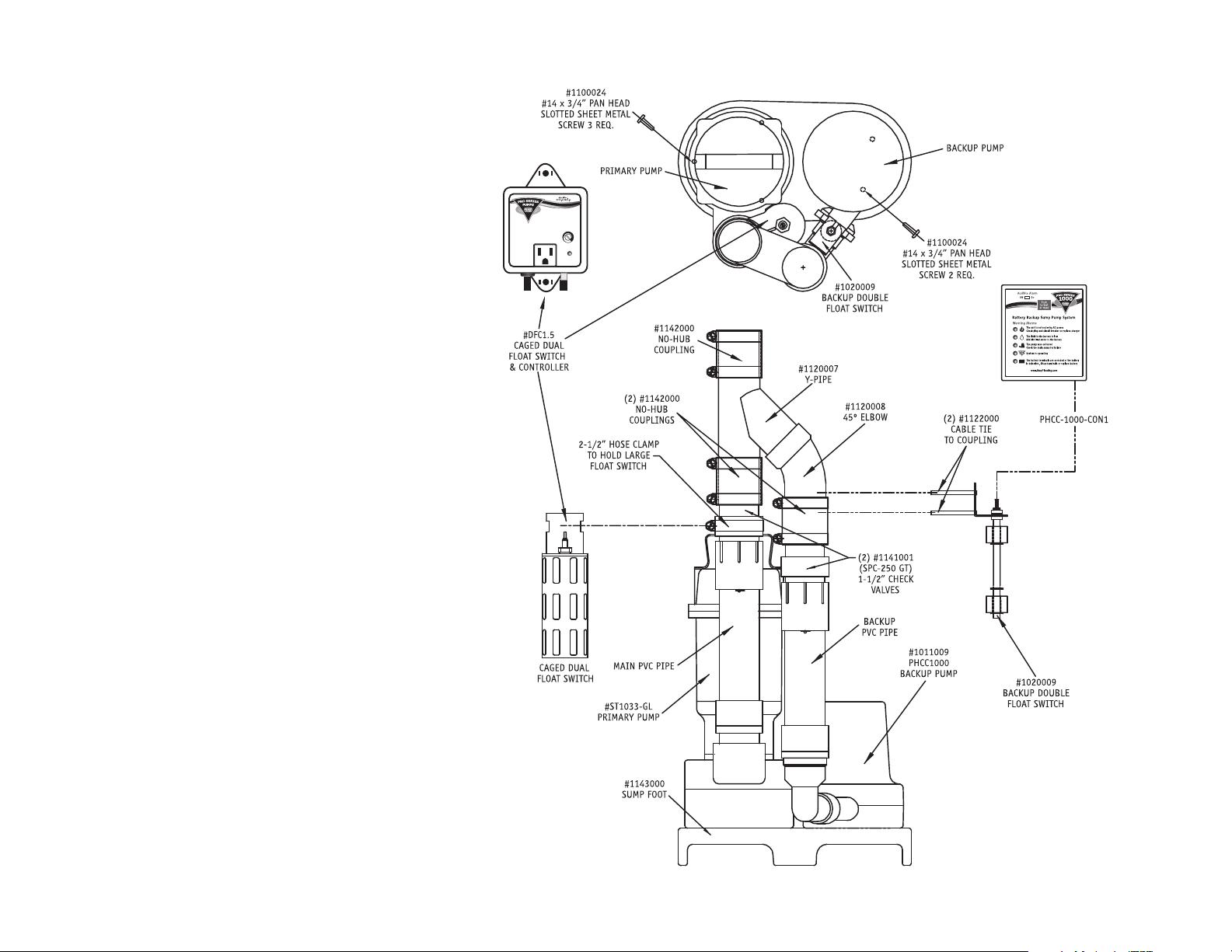
Replacement Parts List
PS -C11 Description Part No.
Controller for backup pump PHCC-1000-CON1
Dual float switch with controller for AC pump DFC1
1/3 HP AC sump pump ST1033-GL
PHCC 1000 backup pump 1011009
Battery box 1113003
PVC “Y” fitting 1120007
Battery cap with hole 1125000
Sump foot 1143000
Stainless steel screw, #14 x 3/4” * 1100024
45º PVC pipe fitting, 1-1/2” * 1200008
Pipe adapter for backup pump,
1-1/2” FTP x 1-1/2” slip * 1120009
Wire tie for float switch, 11” * 1122000
Stainless steel hose clamp, 2-1/2” diameter * 1122002
Check valve, 1-1/2” MPT x 1-1/2” SLIP * 1141001
No-hub coupling, 1-1/2” * 1142000
BOTTOM VIEW
*Stock items available in plumbing department
Call 800-991-0466 to order parts.
Page 15
SIDE VIEW
Page 17

Primary Pump Troubleshooting Guide
DANGER
!
Read safety warnings & instructions before attempting any repairs or maintenance.
Backup Pump Troubleshooting Guide
DANGER
!
Read safety warnings & instructions before attempting any repairs or maintenance.
Potential Cause THE PUMP WILL NOT START OR RUN Solutions
Pump is not plugged in . . . . . . . . . . . . . . . . . . . .
No AC power . . . . . . . . . . . . . . . . . . . . . . . . . . . .
Poor power source . . . . . . . . . . . . . . . . . . . . . . . .
Locked impeller . . . . . . . . . . . . . . . . . . . . . . . . .
Defective float switch . . . . . . . . . . . . . . . . . . . . .
Defective pump . . . . . . . . . . . . . . . . . . . . . . . . .
Plug pump in properly (see instructions)
Check circuit breaker or fuse, and GFI reset button
Check circuit line wires, cable and outlet
Remove strainer and clear obstruction
Replace float switch with new float switch
Replace pump with new pump
Potential Cause THERMAL PROTECTOR TRIPPING OR NOT FUNCTIONING Solutions
Locked impeller . . . . . . . . . . . . . . . . . . . . . . . . .
Incorrect power supply . . . . . . . . . . . . . . . . . . . .
Pump running continuously with no water present . .
Remove strainer and clear obstruction
Check power supply source and voltage
Check float switch
Potential Cause PUMP STARTS AND STOPS TOO FREQUENTLY Solutions
Float switches mounted too low . . . . . . . . . . . . . .
Water back flowing from pipe . . . . . . . . . . . . . . . .
Malfunctioning float switch . . . . . . . . . . . . . . . . .
Raise both float switches
Install or replace check valve
Replace float switch with new float switch
Potential Cause PUMP WILL NOT SHUT OFF Solutions
Clogged or frozen discharge . . . . . . . . . . . . . . . . .
Blocked intake strainer . . . . . . . . . . . . . . . . . . . .
One or both of the floats is obstructed and cannot
drop down . . . . . . . . . . . . . . . . . . . . . . . . . . . . .
Defective float switch . . . . . . . . . . . . . . . . . . . . .
Check valve is stuck . . . . . . . . . . . . . . . . . . . . . .
Clear blockage or thaw frozen line
Clear debris from intake strainer
Clear debris from inside the float cage (Loosen nut on
top of float, then remove c-clip on bottom of float.
Remove debris. Tighten nut on top of float, then
replace c-clip on bottom of float.) When reassembling
the float, the magnetic strip on the inside of the float
should be facing down.
Replace float switch with new float switch
Replace check valve.
Potential Cause INSUFFICIENT OR NO WATER VOLUME Solutions
Check valve on secondary pump will not close and
water re-circulates within the system . . . . . . . . . . .
Partially blocked impeller . . . . . . . . . . . . . . . . . . .
Clogged or frozen discharge pipe . . . . . . . . . . . . . .
Broken or leaking pipe . . . . . . . . . . . . . . . . . . . . .
Low power voltage . . . . . . . . . . . . . . . . . . . . . . .
Check valve is stuck . . . . . . . . . . . . . . . . . . . . . .
Replace the check valve on the secondary pump
Remove strainer and clear obstruction
Clear blockage or thaw frozen line
Repair pipe
Check power voltage, wires and cable condition
Replace check valve.
Potential Cause ABNORMAL SOUND OR VIBRATION Solutions
Check valve is broken . . . . . . . . . . . . . . . . . . . . .
Blocked intake screen . . . . . . . . . . . . . . . . . . . . .
Defective pump . . . . . . . . . . . . . . . . . . . . . . . . .
Replace the check valve
Clear debris from intake screen
Replace pump
Potential Cause BATTERY FLUID LOW Solutions
The battery fluid is low . . . . . . . . . . . . . . . . . . . . . .
The fluid sensor is installed improperly . . . . . . . . . . .
Not using a Pro Series battery . . . . . . . . . . . . . . . . .
Add distilled water to each cell of the battery
The fluid sensor should be inserted into the designated
hole on the top of the battery and pushed down
This feature cannot be used. Attach the fluid sensor to
the positive post of the battery
Potential Cause BATTERY PROBLEM Solutions
Terminals are corroded . . . . . . . . . . . . . . . . . . . . . .
Cables are loose . . . . . . . . . . . . . . . . . . . . . . . . . . .
Battery is discharged below 25% . . . . . . . . . . . . . . .
Battery is old or damaged . . . . . . . . . . . . . . . . . . . .
Clean terminals and cables
Tighten wing nuts
Replace battery if power is out. There is only 1 hour of
continuous pumping power left. Battery will recharge
when power is restored
Replace battery
Potential Cause POWER FAILURE Solutions
Power outage . . . . . . . . . . . . . . . . . . . . . . . . . . . .
An outlet, fuse, or circuit breaker has failed . . . . . . .
The charger is unplugged from the wall or the back of
the controller . . . . . . . . . . . . . . . . . . . . . . . . . . . .
The control unit is receiving less than 110 volts from
the outlet . . . . . . . . . . . . . . . . . . . . . . . . . . . . . . .
None. The backup pump will run off of the battery. Flip
the alarm switch to the off position to silence the alarm.
Be sure to flip it back to on when the power is restored.
Try another outlet, replace the fuse, or reset the circuit
breaker
Make sure the power cord is plugged in securely
None, if the utility company has instigated brown outs.
Otherwise, reduce the number of other appliances on the
circuit
Potential Cause PUMP WILL NOT SHUT OFF Solutions
Backup pump is unplugged . . . . . . . . . . . . . . . . . . .
Backup pump is clogged . . . . . . . . . . . . . . . . . . . . .
Backup pump is broken . . . . . . . . . . . . . . . . . . . . . .
Make sure the pump is securely plugged into the back of
the control unit
Remove strainer from pump and clean out any debris
Replace the pump
Potential Cause INSUFFICIENT OR NO WATER VOLUME Solutions
The main AC pump failed because of a power outage .
The water was coming into the sump faster than the
main pump could evacuate it . . . . . . . . . . . . . . . . . .
The float switch on the main AC pump is stuck or
defective . . . . . . . . . . . . . . . . . . . . . . . . . . . . . . .
The main AC pump is broken . . . . . . . . . . . . . . . . . .
The main AC pump could not keep up with the inflow
of water . . . . . . . . . . . . . . . . . . . . . . . . . . . . . . . .
The check valve is stuck and the water cannot pass
through it . . . . . . . . . . . . . . . . . . . . . . . . . . . . . . .
The discharge pipe is clogged or frozen and the water
cannot pass through it . . . . . . . . . . . . . . . . . . . . . .
There is a slight chance of false activation if the float
switch cord is wrapped around the AC power cord
None. The backup pump was activated when needed
None. The backup pump was activated when needed
Free the float switch on the main pump or replace it
Replace the main AC pump
None. The backup pump was activated as needed. If this is a
recurring problem, install a higher capacity main pump
Replace the check valve
Thaw, clean out the blockage, or replace the discharge pipe
. . . .
Move the float switch cord away from the AC power cord
Potential Cause ABNORMAL SOUND OR VIBRATION Solutions
Check valve is broken . . . . . . . . . . . . . . . . . . . . . . .
Discharge pipe is clogged or frozen . . . . . . . . . . . . .
Make sure check valve is functioning, or replace it
Clear the discharge pipe
Page 16
Page 18

Limited Warranty
By opening this package and using this GLENTRONICS, INC. product, you are agreeing to be bound by the terms of the GLENTRONICS, INC. limited warranty (“warranty”) as set out below. Do not use your product until
you have read the terms of the warranty. If you do not agree to the terms of the warranty, do not use the product and return it within the return period stated on your purchase receipt from the retail store or
authorized distributor where you purchased it for a refund.
To the extent permitted by law, this warranty and the remedies set forth are exclusive and in lieu of all other warranties, remedies and conditions, whether oral, written, statutory, express or implied. GLENTRONICS,
INC. disclaims all statutory and implied warranties, including without limitation, warranties of merchantability and fitness for a particular purpose and warranties against hidden or latent defects, to the extent
permitted by law. GLENTRONICS, INC. will not be liable for any incidental, special or consequential damages for breach of any express or implied warranties on this product. In so far as such warranties cannot be
disclaimed, GLENTRONICS, INC. limits the duration and remedies of such warranties to the duration of this express warranty and, AT GLENTRONICS, INC.'s option, the repair or replacement services described below.
Some states (countries and provinces) do not allow limitations on how long an implied warranty (or condition) may last, so the limitation described above may not apply to you.
Any and all causes of action arising from, filed as a result of or in reference to, this warranty or the products described under this warranty shall be governed by and construed under the laws of the State of Illinois.
Any cause of action arising from, filed as a result of or in reference to, this warranty or the products described under this warranty shall be filed only in the Circuit Court of the 18th Judicial District, Lake County,
Waukegan, Illinois, or in the Northern District of Illinois if filed in Federal Court. The maximum liability for any product described in this warranty shall be the cost of product replacement only.
If any term is held to be illegal or unenforceable, the legality or enforceability of the remaining terms shall not be affected or impaired.
What is Covered by this Warranty?
GLENTRONICS, INC. warrants to the end purchaser that its pumps, switch and control unit products are free from defective materials and workmanship for the periods indicated below:
All parts and labor (excluding installation) for a period of:
• 3 years from the date of installation, when used intermittently as a sump pump
The defective product must be returned directly to the factory, postage prepaid with the original bill of sale or receipt to the address listed below. GLENTRONICS, INC., at its option, will either repair or replace the
product and return it postage prepaid.
What is NOT Covered by this Warranty?
This warranty does not cover the cost or value of damaged property, including expressly any property that has been affected by water overflow, seepage or flooding. If GLENTRONICS, INC. determines that a product is
deemed defective under this warranty agreement, it will repair or replace the PRODUCT ONLY. GLENTRONICS, INC. will not cover the cost to reinstall the product, nor will GLENTRONICS, INC. pay the cost of having a
plumber or contractor repair or replace the product.
GLENTRONICS, INC. will not repair or replace a product that was installed incorrectly. A product shall be considered “installed incorrectly” when it deviates in any way from the instructions described in this manual.
This warranty does not cover product problems resulting from handling liquids hotter than 104 degrees Fahrenheit, handling inflammable liquids, solvents, strong chemicals or severe abrasive solutions; user abuse;
misuse, neglect, improper maintenance, commercial or industrial use; improper connection or installation, damages caused by lightning strikes; excessive surges in AC line voltage; water damage to the controller;
other acts of nature, or failure to operate in accordance with the enclosed written instructions.
How to Obtain Warranty Service
Within thirty (30) days of the product’s defective performance, the unit must be shipped, freight prepaid, or delivered to GLENTRONICS, INC. to provide the services described hereunder in either its original carton
and inserts, or a similar package affording an equal degree of protection. Products not received by GLENTRONICS, INC. at the address indicated below within thirty (30) days of the product’s defective performance will
not be considered for warranty service. Products received after three (3) years from the date of purchase, fall outside of the timeframe for warranty service and will not be eligible for warranty service. The product
must be returned to GLENTRONICS, INC. for inspection in order to be considered for warranty service. If the product is not returned to GLENTRONICS, INC. or the product is inspected by any person, plumber,
contractor or business other than GLENTRONICS, INC., this warranty shall no longer be valid. Prior to defective operation, the unit must not have been previously altered, repaired or serviced by anyone other than
GLENTRONICS, INC., or its agent; the serial number on the unit must not have been altered or removed; the unit must not have been subject to accident, misuse, abuse or operated contrary to the instructions
contained in the accompanying manual. The dealer's dated bill of sale, or installer’s invoice must be retained as evidence of the date of purchase and to establish warranty eligibility.
Where are Products Sent for Warranty Service?
Glentronics, Inc., 645 Heathrow Drive, Lincolnshire, IL 60069
How Can I Obtain More Information?
By calling 800-991-0466
Page 17
Page 19
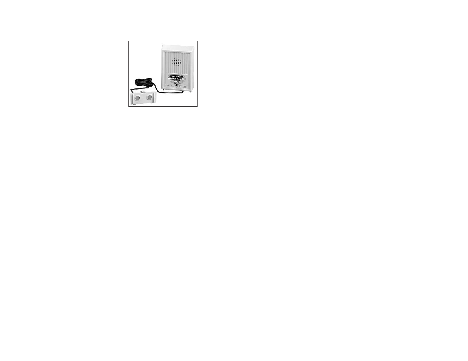
CHECK OUT THIS OTHER PHCC PRO SERIES PRODUCT
WATER ALARM
Minimize the risk of water damage
You can detect leaks before they become bigger
problems by placing a water alarm wherever
there is a risk of water damage…in the utility
room, laundry room, kitchen, bathroom or
basement. The alarm will sound when as little as
1/32” of water reaches the sensor.
© 2009, Glentronics, Inc. 1806062 01/18
Page 18
 Loading...