

Page 1
PHCC Pro Series
Deluxe Float Switch & Controller
Instruction Manual & Safety Warnings
SAVE THESE INSTRUCTIONS. This manual contains important SAFETY
WARNINGS and OPERATING INSTRUCTIONS for the PHCC Pro Series
Deluxe Float Controller with dual float (DFC2) and vertical float (VSC2).
You will need to refer to it before attempting any installation or
maintenance.
ALWAYS keep these instructions with the unit so that they will be
easily accessible. Failure to read and follow these warnings and
instructions could result in property damage, serious injury, or death.
WARNING
• ALWAYS disconnect the pump and float controller from the power
source before servicing or making adjustments.
• NEVER handle the controller, float switch, pump or motor with wet hands or
when standing on a wet or damp surface while the pump or controller is
plugged into the power source.
• MAKE SURE THERE IS A PROPERLY GROUNDED RECEPTACLE AVAILABLE.
This controller is wired with a 3-prong grounded plug. To reduce the risk of
electric shock, be certain that it is only connected to a properly grounded,
3-prong receptacle. If you have a 2-prong receptacle, have a licensed
electrician replace it with a 3-prong receptacle according to local codes
and ordinances.
• NEVER bypass grounding wires or remove the ground prong from the
controller.
• DO NOT use an extension cord. The electrical outlet should be within the
length of the pump’s power cord, and at least 4 feet above the floor level to
minimize potential hazards from flood conditions.
• DO protect the electrical cord from sharp objects, hot surfaces, oil, and
chemicals. Avoid kinking the cord.
• MAKE SURE the supply circuit has a fuse or circuit breaker rated to handle
the power requirements noted on the nameplate of the pump.
CAUTION
• DO NOT expose the control unit to any type of moisture, water, rain
or snow.
• DO NOT operate the pump or control unit if it has been damaged in
any way.
• DO NOT use the caged dual float switch with pumps in pits handling raw
sewage, salt water or hazardous liquids. This product is for ground water
applications only.
• DO NOT use the vertical float switch with pumps in pits handling salt water
or other hazardous liquids.
• DO NOT use in continuous duty applications such as fountains or ponds.
• DO NOT disassemble the pump or control unit. When service is required,
contact Glentronics technical support at 800-991-0466, option 3.
Return the product to the manufacturer for any repairs at the
following address:
Glentronics, Inc., 645 Heathrow Drive, Lincolnshire, IL 60069
NOTICES
• The control unit must receive 115V AC +/- 5% and 60 Hz from the AC outlet.
• The controller will not provide protection during a power outage. With the
risk of property damage from high water levels, the addition of a PHCC Pro
Series battery backup sump pump system is highly recommended.
• After the initial installation, be sure to check the operation by filling the
sump with water and observing the pump operation through one full cycle.
Risk of electric shock. To reduce this risk,
observe the following precautions
To reduce the risk of hazards that can cause injury or
property damage, observe the following precautions
Installation
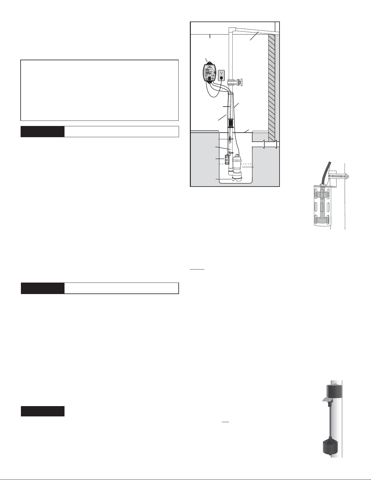
FLOOR JOIST
MOUNTED DELUXE
FLOAT CONTROLLER
PLUGGED INTO
AC OUTLET
WATER SENSOR WIRE
FLOAT WIRE
WATER SENSOR
AIR BLEED
HOLE
DUAL
FLOAT
SUMP FOOT
SLOPE
PIPE
DOWN
DISCHARGE
PIPE
VALVE
PUMP
WIRE
UNION/CHECK
VALVE
GAT E
PIT COVER
DRAIN TILE
PRO SERIES
PUMP
Dual Float Switch (Model DFC2)
The dual float switch contains two large floating rings
enclosed within a protective cage. Water will lift the
bottom float by a
1
⁄4”, which will activate the pump. If
for any reason the lower float does not activate the
pump, the water will rise and activate the second switch.
As the pump evacuates the water from the pit, the floats will drop. The
pump will run for an additional 10 seconds to evacuate the pit completely
after the float drops. The float switch wire includes a connector that can
be separated from the controller when the wire needs to be threaded
through small openings. Note: When mounting the float switch, position the
bottom of the cage at the height you want the pump to activate.
Installing the Dual Float
The PHCC Pro Series dual float switch is easy to install by using the
enclosed stainless steel hose clamp.
1. Hold the float switch to the discharge pipe so the cage is below the
bracket.
2. Secure the float to the pipe with the enclosed hose clamp, but do not
completely tighten the clamp at this time.
3. Position the float switch to a level where the bottom of the float cage
is no lower than 3” above the bottom of the pump. To avoid debris
pouring onto the float, it should be positioned on the side of the
discharge pipe opposite the drain tile. Note: It is important to mount
the float below the drain tile that empties into the pit. Mounting it above
the drain tile would allow water to fill the drain tile before the pump is
activated to pump out the water.
4. Once the float switch is in the desired position, tighten the clamp.
Vertical Float Switch (Model VSC2)
The vertical float switch contains a single large float.
Water will lift the float by a
1
⁄2”, which will activate the
pump. As the pump evacuates the water from the pit, the
float will drop. The pump will run for an additional 10
seconds to evacuate the pit completely after the float
drops. Note: There are two rubber stoppers on the float
switch rod. Do not remove or alter their position as it will
disrupt the timing of the controller and how long the pump
runs. The float switch wire includes a connector that can
be separated from the controller when the wire needs to be
threaded through small openings. Note: When mounting
the float switch, position the bottom of the float at the
height you want the pump to activate.
Instructions
Prior to Installation
1. Visually inspect the
product. Products may be
damaged during shipping.
If the product has been
damaged, contact your
place of purchase or
Glentronics, Inc. before
installation.
2. Thoroughly read the
instructions provided to
learn specific details
regarding installation and
use. This manual should be
retained for future
reference.
Page 2
Installing the Vertical Float
The PHCC Pro Series float switch is easy to install by using the enclosed
stainless steel hose clamp.
1. Hold the float switch to the discharge pipe so the float is below the
bracket.
2. Secure the float to the pipe with the enclosed hose clamp, but do not
completely tighten the clamp at this time.
3. Position the float switch to a level where the bottom of the float is no
lower than 3” above the bottom of the pump. To avoid debris pouring
onto the float, it should be positioned on the side of the discharge
pipe opposite the drain tile. Note: It is important to mount the float
below the drain tile that empties into the pit. Mounting it above the
drain tile would allow water to fill the drain tile before the pump is
activated to pump out the water.
4. Once the float switch is in the desired position, tighten the clamp.
Deluxe Float Controller
The benefit of this controller is that it will sound an alarm when problems
exist or maintenance is needed. The controller will also run the pump
once a week for approximately four (4) seconds. This test will exercise the
pump and help ensure the pump is working properly.
The PHCC Pro Series Deluxe Float Controller features a series of warnings
(audible and visual) that pinpoint potential problems with the pump,
switch and power conditions. The controller will sound an alarm when
power has been interrupted, when the pump has run for more than 10
minutes continuously, or when the 9V battery is low. The 9V battery (sold
separately) runs the controller during a power outage, allowing it to sound
an alarm if the circuit breaker trips, the controller is not plugged in
securely, or the home’s power is interrupted.
Note: The 9V battery will only power the switch, not the pump.
Installing the Deluxe Float Controller
1. Mount the controller to the wall through the 2 holes on the cabinet
using the proper mounting hardware for the application. The controller
should be mounted at least 4‘ from the floor and within 4’ of the
outlet.
2. Open the plastic door on the top of the unit and using a flat head
screwdriver adjust the dial to select the number of seconds that the
pump will run after the float drops. The dial can be adjusted from 5-45
seconds. The manufacturer default is about 10 seconds. Install a 9V
alkaline battery and replace the plastic door.
3. Plug the control box into a properly grounded, 3-prong receptacle.
Then, plug the pump into the receptacle on the control box. Do not use
an extension cord.
4. Make sure the Power Failure Alarm slide switch is in the ON position.
5. Plug the float switch into the bottom of the controller.
Completing the Installation
1. After the initial installation, be sure to check the pump operation by
filling the sump with water and observing the pump through one full
cycle. The pump should run for 10 seconds after the float drops to its
original position.
2. Replace the pit cover making sure not to pinch or crimp the pump wire
with the cover. The pit cover either has a ‘hole punch’ that will allow
the cord to be passed through it, or a hole can be drilled in the cover.
High Water Alarm Accessory for the Deluxe Controller
(Requires the additional purchase of model PS-WS)
Water Sensor
The water sensor is designed to warn you of a potential flood. If you are
installing it in the sump pit, it must to be installed between the basement
floor and the primary float switch. If there is a failure with either the
main pump or the plumbing system, the water level will rise past the
primary float switch and activate the water sensor. When the water sensor
is activated, it will trigger a warning light, an audible alarm, and the
remote terminal on the controller.
This water sensor is only designed to give you a warning of a potential
problem; it will not activate the primary pump.
Installing the Water Sensor
The water sensor should be mounted near the top of the pit or where it is
appropriate for your installation (see diagram). Attach the water sensor
very securely with the included plastic wire tie. Be sure the water sensor
is positioned vertically with the mounting bracket at the top. Plug the
water sensor into the bottom of the controller. Do not tilt the water
sensor. Do not position the water sensor on the side of the discharge pipe
facing the drain tile or any incoming rush of water.
Testing the Water Sensor
Lift up the float on the water sensor with your fingers. As long it is up,
the high water alarm warning light and the audible alarm should be on.
When the float is down, the warning light and audible alarm will turn off.
Understanding the Warnings & Alarms
AC power is out
There are several causes for power
failure. The most common causes are a
power outage by the electric company
or a tripped circuit breaker. Although
the deluxe controller can not run the
pump, it will sound an alarm indicating
the loss of power. This will allow the
homeowner to address the problem.
If this warning light and alarm are on,
the control box is not receiving AC
power for one of many reasons:
1. The control box is not plugged in
2. The power to the house is out
3. The circuit breaker to that outlet has
been tripped
4. A power brownout is taking place
Power Failure Alarm slide switch
When the controller is not receiving AC power, the monitoring features
and the audible alarms are powered by the 9-volt battery. This type of
battery will power the controller for many hours, but not indefinitely.
Once the source of the AC power alarm is determined, it is suggested that
the Power Failure Alarm slide switch be turned to the OFF position until
the power is restored. This will preserve the battery and silence the alarm.
When AC power is restored, slide this switch back to the ON position.
Note: If the AC power is restored and the slide switch is in the OFF position,
the alarm and light for the 9-volt battery warning will activate, even if the
battery is good. This is a reminder to reset the alarm. Slide the switch to
the ON position. If the battery is good, the light will go out. If the alarm
continues to sound, replace the battery.
The system is operating
This light should be ON and flashing at all times. It is included to
indicate that the system is monitoring the sump conditions.
This light will not illuminate when:
1. The power is out and the Power Failure Alarm slide switch is in the
OFF position
2. The power is out and the 9V battery is discharged
3. The controller is not functioning. Contact the Glentronics service
department
The 9-volt battery is low
1. The 9-volt battery located in the top of the control box is coming to
the end of its useful life. Replace it with a new 9-volt alkaline battery.
2. The Power Failure Alarm switch is in the OFF position. It must be in
the ON position at all times, except when silencing an actual power
failure condition.
Pump or float problem
This key feature monitors the time that the float switch is up
continuously or in the activated position. It is unusual for a pump run
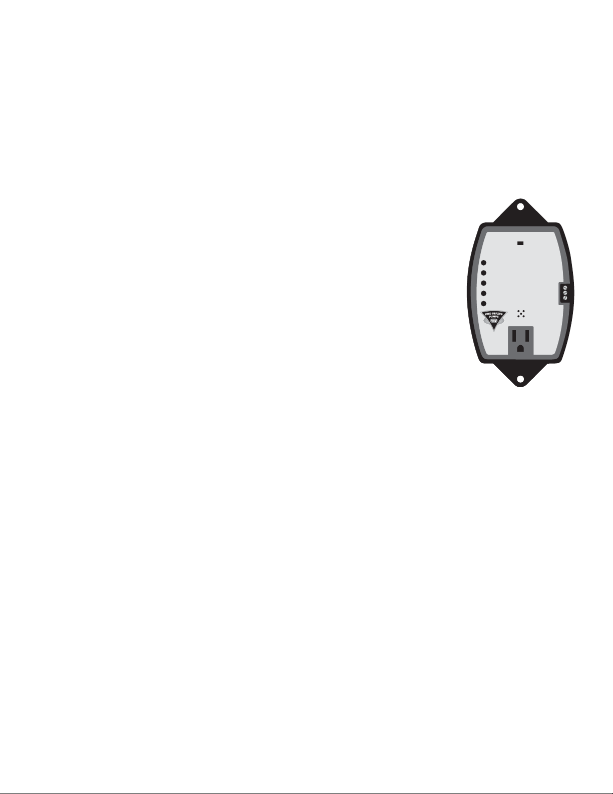
Power Failure Alarm
On Off
Slide switch to OFF during power failures
to conserve battery energy and silence alarm
AC power is out
Make sure this controller is plugged into the wall outlet
Check the circuit breaker
The system is operating
Light should be flashing
9 volt battery low or slide switch is OFF
Replace 9 volt alkaline battery or move switch to ON
Pump or float problem
The pump has run continuously for 10 minutes
Refer to the instructions for possible causes
High water alarm (optional feature)
Water has reached the high water sensor
www.stopflooding.com
12 Amps maximum
Model No. DFC2
Glentronics, Inc.
800.991.0466
Common
Deluxe
Float
Controller
Consider a
Pro Series
Battery Backup
Sump Pump
System
Remote
Connection
N.C.
N.O.
Page 3

for 10 or more minutes continuously. This can occur for many different
reasons. Either the float is stuck in the up position, there is a mechanical
problem with the pump, or there is a problem with the plumbing
connections. Please refer to the Troubleshooting Guide on the last page.
High water alarm (optional feature*)
When water reaches the optional water sensor, it will activate the warning
light, audible alarm, and remote terminal. The activation of the water
sensor could indicate that there is a failure of the main pump or plumbing
problem. Please refer to the Troubleshooting Guide on the last page.
*This feature requires the additional purchase of the water sensor
(Model # PS-WS).
Glentronics, Inc., Lincolnshire, IL 60069
800-991-0466
www.stopflooding.com
LIMITED WARRANTY
By opening this package and using this GLENTRONICS, INC. product, you are agreeing to be bound by the terms of the GLENTRONICS, INC. limited warranty
(“warranty”) as set out below. Do not use your product until you have read the terms of the warranty. If you do not agree to the terms of the warranty, do not use
the product and return it within the return period stated on your purchase receipt from the retail store or authorized distributor where you purchased it for a
refund.
To the extent permitted by law, this warranty and the remedies set forth are exclusive and in lieu of all other warranties, remedies and conditions, whether oral,
written, statutory, express or implied. GLENTRONICS, INC. disclaims all statutory and implied warranties, including without limitation, warranties of merchantability
and fitness for a particular purpose and warranties against hidden or latent defects, to the extent permitted by law. GLENTRONICS, INC. will not be liable for any
incidental, special or consequential damages for breach of any express or implied warranties on this product. In so far as such warranties cannot be disclaimed,
GLENTRONICS, INC. limits the duration and remedies of such warranties to the duration of this express warranty and, AT GLENTRONICS, INC.'s option, the repair or
replacement services described below. Some states (countries and provinces) do not allow limitations on how long an implied warranty (or condition) may last, so
the limitation described above may not apply to you.
Any and all causes of action arising from, filed as a result of or in reference to, this warranty or the products described under this warranty shall be governed by
and construed under the laws of the State of Illinois. Any cause of action arising from, filed as a result of or in reference to, this warranty or the products described
under this warranty shall be filed only in the Circuit Court of the 18th Judicial District, Lake County, Waukegan, Illinois, or in the Northern District of Illinois if
filed in Federal Court. The maximum liability for any product described in this warranty shall be the cost of product replacement only.
If any term is held to be illegal or unenforceable, the legality or enforceability of the remaining terms shall not be affected or impaired.
What is Covered by this Warranty?
GLENTRONICS, INC. warrants to the end purchaser that its pumps, switch and control unit products are free from defective materials and workmanship for the
periods indicated below:
All parts and labor (excluding installation) for a period of:
• 1 year from the date of purchase, when purchased individually for use with another brand of sump pump
• When purchased with a PHCC Pro series pump, the Deluxe Float Controller and float switch are covered under the pump’s warranty
The defective product must be returned directly to the factory, postage prepaid with the original bill of sale or receipt to the address listed below. GLENTRONICS,
INC., at its option, will either repair or replace the product and return it postage prepaid.
What is NOT Covered by this Warranty?
This warranty does not cover the cost or value of damaged property, including expressly any property that has been affected by water overflow, seepage or flooding.
If GLENTRONICS, INC. determines that a product is deemed defective under this warranty agreement, it will repair or replace the PRODUCT ONLY. GLENTRONICS,
INC. will not cover the cost to reinstall the product, nor will GLENTRONICS, INC. pay the cost of having a plumber or contractor repair or replace the product.
GLENTRONICS, INC. will not repair or replace a product that was installed incorrectly. A product shall be considered “installed incorrectly” when it deviates in any
way from the instructions described in this manual.
This warranty does not cover product problems resulting from handling liquids hotter than 104 degrees Fahrenheit, handling inflammable liquids, solvents, strong
chemicals or severe abrasive solutions; user abuse; misuse, neglect, improper maintenance, commercial or industrial use; improper connection or installation,
damages caused by lightning strikes; excessive surges in AC line voltage; water damage to the controller; other acts of nature, or failure to operate in accordance
with the enclosed written instructions.
How to Obtain Warranty Service
Within thirty (30) days of the product’s defective performance, the unit must be shipped, freight prepaid, or delivered to GLENTRONICS, INC. to provide the services
described hereunder in either its original carton and inserts, or a similar package affording an equal degree of protection. Products not received by GLENTRONICS,
INC. at the address indicated below within thirty (30) days of the product’s defective performance will not be considered for warranty service. Products received
after one (1) year from the date of purchase, fall outside of the timeframe for warranty service and will not be eligible for warranty service. The product must be
returned to GLENTRONICS, INC. for inspection in order to be considered for warranty service. If the product is not returned to GLENTRONICS, INC. or the product is
inspected by any person, plumber, contractor or business other than GLENTRONICS, INC., this warranty shall no longer be valid. Prior to defective operation, the
unit must not have been previously altered, repaired or serviced by anyone other than GLENTRONICS, INC., or its agent; the serial number on the unit must not
have been altered or removed; the unit must not have been subject to accident, misuse, abuse or operated contrary to the instructions contained in the
accompanying manual. The dealer's dated bill of sale, or installer’s invoice must be retained as evidence of the date of purchase and to establish warranty
eligibility.
Where are Products Sent for Warranty Service?
Glentronics, Inc., 645 Heathrow Drive, Lincolnshire, IL 60069
How Can I Obtain More Information?
By calling 800-991-0466.
Page 4

Troubleshooting Guide
The pump will not start or run
Thermal protector tripping or
not functioning
Pump starts and stops too
frequently
Pump will not shut off
Insufficient or no water
volume
Abnormal sound or vibration
Pump unexpectedly turns off
for 5 seconds
*Consult a licensed electrician.
If the above solutions do not solve the problem, contact Glentronics customer service 800-991-0466, option 3.
(Always unplug the pump from the controller before performing any maintenance)
Pump is not plugged in
Water is not high enough to activate the pump
Open circuit
Poor power source
Low voltage
Bad power cable
Locked impeller
Defective float switch
Defective pump
Locked impeller
Incorrect power supply
Overburdened due to heavy sand content in the water
Pump running continuously with no water present
Float switch mounted too low
Water flowing back from pipe
Malfunctioning float switch
Clogged or frozen discharge
Blocked intake strainer
One or both of the floats is obstructed and
cannot drop down
Defective float switch
Check valve installed with no air bleed hole in
pipe or pump
Check valve is stuck or installed upside down
Check valve on secondary pump will not close
and water re-circulates within the system
Worn impeller
Partially blocked impeller
Clogged or frozen discharge
Broken or leaking pipe
Low power voltage
Check valve installed with no air bleed hole in
pipe or pump
Check valve is stuck or installed upside down
Pump is air locked
Check valve on secondary pump will not close
and water re-circulates within the system
Blocked intake screen
Broken impeller
Pump is experiencing an anti air lock safety
feature
Plug pump in properly (see instructions)
Make sure float switch is positioned properly
Check circuit breaker or fuse
Check circuit line wires and cable*
Check line wires and source voltage*
Replace with new cable*
Remove strainer and clear obstruction
Replace float switch with new float switch
Replace pump with new pump
Remove strainer and clear obstruction
Check power supply source and voltage
Use water filter or replace with a higher wattage pump
Check float switch
Raise float switch
Install or replace check valve
Replace float switch with new float switch
Clear blockage or thaw frozen line
Clear debris from intake strainer
Clear debris from inside the float cage (Loosen nut on top of float, then
remove c-clip on bottom of float. Remove debris. Tighten nut on top of
float, then replace c-clip on bottom of float.) When reassembling the float,
the magnetic strip on the inside of the float should be facing down.
Replace float switch with new float switch
An air bleed hole of 3/16” (4.76mm) needs to be drilled in the discharge
pipe below the check valve and pit cover
Reverse or replace check valve. Make sure the check valve is installed with
the flow arrow pointing up and out of the pit.
Replace the check valve on the secondary pump
Replace impeller & adjust spacing between impeller and cover
Remove strainer and clear obstruction
Clear blockage or thaw frozen line
Repair piping
Check power voltage, wires and cable condition
An air bleed hole of 3/16” (4.76mm) needs to be drilled in the discharge
pipe below the check valve and pit cover
Reverse or replace the check valve. Be sure check valve is installed with
flow arrow pointing up and out of the pit
Remove debris from the air bleed hole
Replace the check valve on the secondary pump
Clear debris from intake screen
Replace impeller with new one
Pump is frequently cycling on and off. The controller has a safety feature
that turns the pump off for 5 seconds if it detects a possible air lock. This
is normal. No action is required.
1806103 02/16
 Loading...