

Page 1
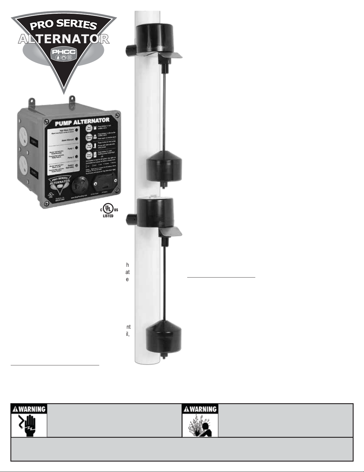
Model No. DVSA
Pump Alternator System
Installation Instructions
Features:
• Prolongs pump life by alternating two
primary pumps
• Runs one pump at a time
•
If one pump fails the other pump will take
over and an audible alarm will sound
• Flashing light will indicate which pump
is failing
• Remote terminal allows the unit to
connect to any security system, auto
dialer or other device
• Includes two vertical float switches
• If one float switch fails the other float
switch will take over and an audible
alarm will sound
•
Angled receptacles to accept a standard
or right angled pump plugs
• 15 Amps max.
• 9V battery back-up for "High Water
Alarm" alarm
• Plug and play for easy installation
• 9 foot long power cord
The PHCC Pro Series Pump Alternator is designed to
operate two primary pumps. Every time the float switch
is activated, it will automatically alternate the pump that
turns on. This will prolong the life of both pumps. If one
of the pumps fails to turn on, the Alternator will
automatically switch to the other pump. If this occurs
three times in a row, a light will start flashing indicating
exactly which pump is failing.
For added reliability, the system features two separate
vertical float switches. They are both mounted at different
levels in the sump pit. Should the lower float switch fail,
the higher float switch will turn the pump on and will
sound a High Water Alarm.
Pro Series Pump Alternator includes:
• Control unit
• Two vertical float switches
• Two hose clamps for mounting the float switches
ELECTRICAL SHOCK HAZARD
Disconnect power before installing or servicing this
product. A qualied service person must install and
service this product according to applicable electrical and plumbing codes.
You will also need to supply:
• Two (2) Primary pumps Consider one of our strong and
dependable primary pumps. All PHCC Pro Series primary
pumps are built to run continuously 24 hours a day, 365 days
a year. Using them in this application will greatly extend their life.
(Visit www.StopFlooding.com for more information)
• 9V heavy duty-alkaline battery
• Proper mounting hardware
• 1½” rigid PVC pipe and fittings
• PVC primer and cement
• A union with hose clamps or a “Y” connector and
two (2) check valves, depending on the installation
method you use
• PHCC Pro Series Sump Foot is recommended which
provides a platform for both pumps, keeping them
elevated and away from pit debris
EXPLOSION OR FIRE HAZARD
Do not use this product with ammable liquids.
Do not install in hazardous locations as dened by
National Electrical Code, ANSI/NFPA 70.
Failure to follow these precautions could result in serious injury or death. Replace product immediately if switch cable becomes damaged
or severed. Keep these instructions with warranty after installation. This product must be installed in accordance with National Electric Code,
ANSI/NFPA 70 so as to prevent moisture from entering or accumulating within boxes, conduit bodies, ttings, oat housing, or cable.
Page 2
Pump & Pipe Installation Instructions
Installing the Alternator Control Unit
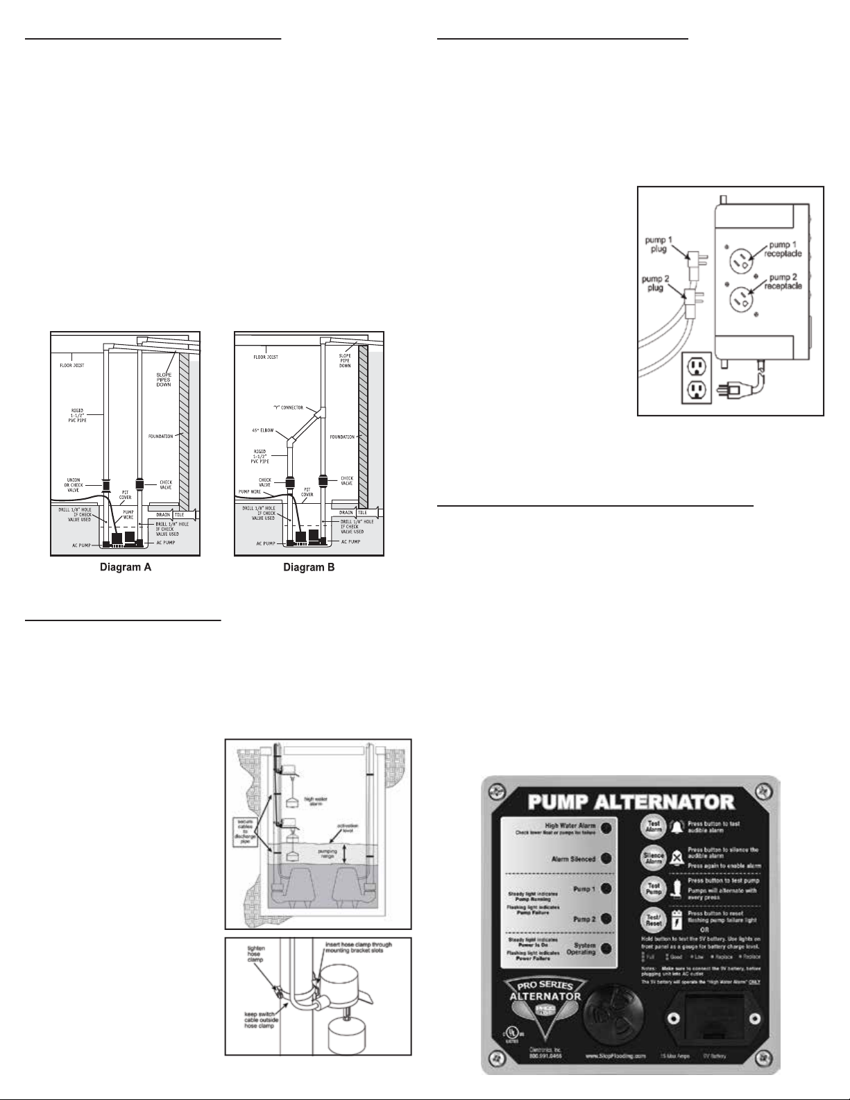
There are two basic methods that can be used to install both pumps together, a
direct discharge to the outside of the building, or a connection to an existing
discharge pipe. It is highly recommended to install the second pump with a direct
discharge to outside (Diagram A). By using this method, there will always be an
outlet for the water from the sump. For this, you will need to drill a hole through the
wall to the outside of the house.
If the direct discharge method is not possible or convenient, both pumps can
be connected to the same discharge pipe by installing a “Y” connector and
two (2) check valves (Diagram B).
CAUTION
When a check valve is used, a 1/8 in. (3.2mm) air bleed hole must be drilled in
the PVC pipe above the pump. Drill the hole at a 45° angle toward the bottom
of the sump to avoid splashing water outside the sump pit. Make sure the
hole is above the water line, and below the check valve. If a hole is not drilled
above the pump, an air lock may prevent the pump from operating.
1. Mounting the Control Unit
Mount the controller to the wall through four (4) holes on the cabinet
using the proper mounting hardware for the application.
CAUTION
Do not mount the control unit anywhere that it will be susceptible to
moisture or flooding.
2. Install 9V Battery
Open the battery compartment on
the front panel of the unit. Install a
9V battery and close the battery
compartment.
Note: Battery is not included, use a
heavy-duty alkaline battery.
3. Connect AC Power Cord
Plug the AC power cord into a
properly grounded, 3-prong
receptacle.
4. Connect Pumps
Plug both pumps into receptacles
located on the left side of the
control unit (Diagram E)
Diagram E
Installing the Float Switches
Determine desired activation level and pumping range as shown in Diagram C.
Pump range can be adjusted by moving the float stop up or down on the rod.
CAUTION
Do not install either float switch in direct flow of incoming water.
Diagram C
1. Insert the hose clamp through
slots in the mounting bracket as
shown in Diagram D.
2. Position the hose clamp around
the discharge pipe.
Note: cable should remain outside
of the hose clamp. Tighten the hose
clamp securely.
3. Mount the float switch labeled
LOWER below the UPPER
float switch.
Understanding the Operation of the Alternator
The Pro Series Alternator features two float switches and is designed to
alternate the operation of two primary pumps. It also has a remote terminal on
the side of the control unit that can be connected to an auto dialer, security
system or other devices.
The pumps will alternate with every activation of the float switch. The pumps
will not operate together in any case. Should one pump fail to turn on, the
water level will rise higher and activate the UPPER float switch. This float
switch will automatically turn on the other pump. If this happens 3 times in a
row, you will receive a flashing light next to the pump that is failing.
Should the LOWER float switch fail, the water level will rise and activate the
UPPER float switch, which will operate the pumps during this failure. When
the UPPER float switch activates for any reason, the High Water Alarm will
sound.
4. They should be approximately 2”
apart (Diagram C). The LOWER
float switch will operate the pump
on a daily basis. The UPPER float
switch will only be used if the
LOWER float switch or one the
pumps were to fail.
Diagram D
Page 3
Understanding the Warning Lights
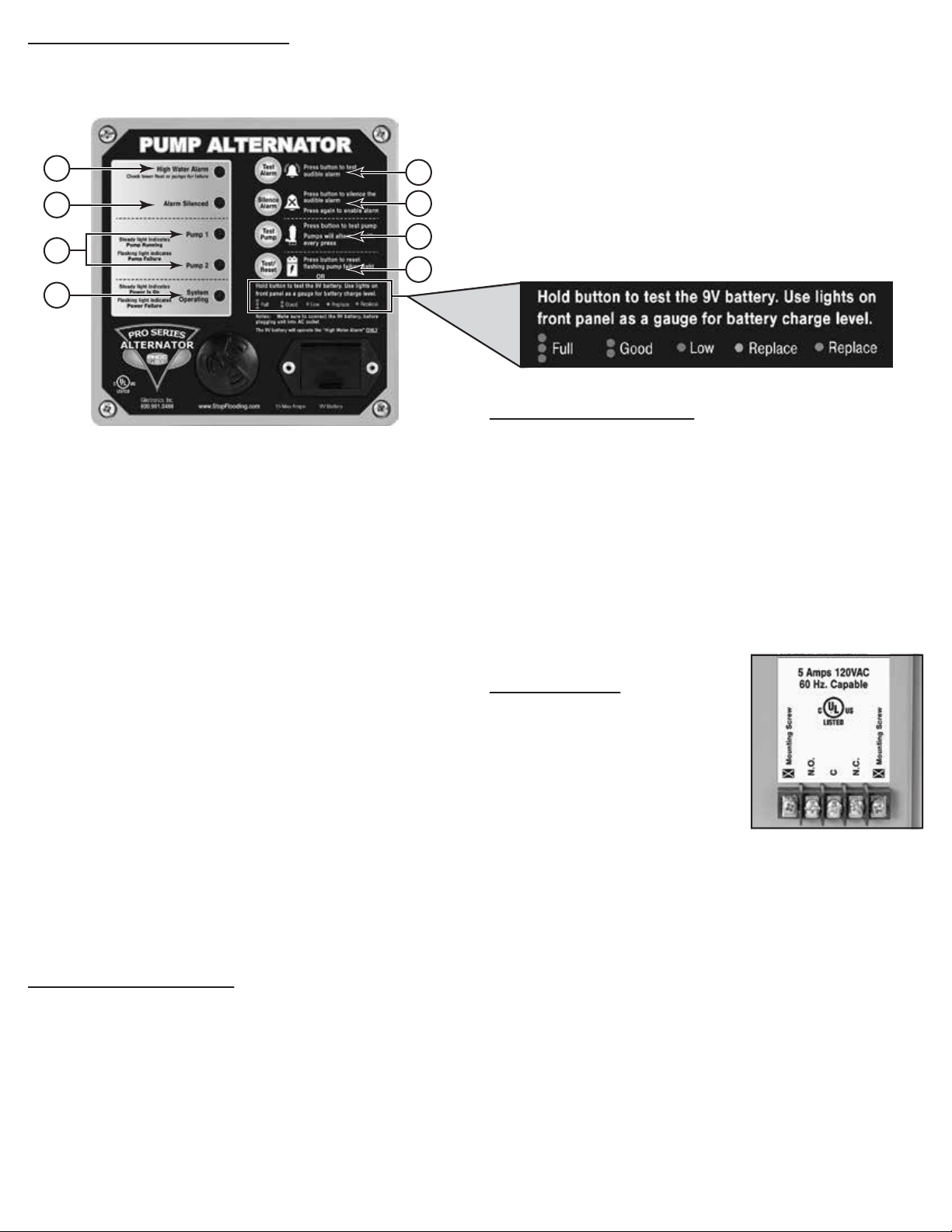
The Pro Series Alternator features a series of lights that either pinpoint
potential problems or give you the status of the system. In addition, an
alarm will sound to alert of a problem.
1
2
A
B
C
3
D
4
C Test Pump
Press this button to test your pumps. Only one pump will run with every press
and will run a long as you are holding the button. The pumps will alternate with
every press. A green light next to Pump 1 or Pump 2 will come on depending
on which pump is running. If a pump doesn’t run, check the pump for failure.
D Test/Reset
Press this button to reset the pump failure green flashing light. Keep in mind
that the High Water Alarm will go off by itself when the UPPER float switch
deactivates. This button resets the flashing green light that comes on when
a pump is failing next to Pump 1 or Pump 2.
This button is also used to test the 9V battery. Press and hold this button
test the 9V battery. Use the lights on the front panel as a gauge for battery
charge level (see picture below).
Testing the Float Switches
1 High Water Alarm
If this warning light and alarm is on, it means that the UPPER float
switch has been activated. This means there is a failure with the
LOWER float switch or one of the pumps. Check the list below before
you replace the pump or the float switch.
• Manually activate the LOWER float switch
•
• If one of the green Pump lights comes on but the pump doesn’t
turn on, one of the pumps may be bad
2 Alarm Silenced
This light will flash yellow when the alarm is silenced.
3 Pump 1 & 2
These lights will come on green when the one of the pumps is running.
The light will indicate which pump is running. Only one light will be on
at a time since both pumps can’t run at the same time. When the light
is on steady green, it means that the pump is operating. If the light is
flashing green, it means that pump is failing. Check the list below
before you replace the pump.
• Verify by manually activating the float switch or by pressing the test
button that the pump is failing
• If one of the pumps fails to turn, replace it
4 System Operating
This light should be on as long as there is power coming from the
outlet and the 9V battery. If it is slowly flashing, it means there is no
power coming into the unit. Make sure it’s plugged in all the way and
the outlet is good. If it’s flashing fast, it means that the 9V battery is
not installed or dead. Replace the 9V battery.
If no green Pump lights come on, the LOWER float switch may be bad
Understanding the Buttons
The Pro Series Alternator features 4 buttons. These buttons are designed for
your convenience to test different features of the system and to silence the
audible alarm.
A Test Alarm
Press and hold this button to test the audible alarm. The alarm will sound
and the High Water Alarm light will be on as long as you hold the button.
B Silence Alarm
Press this button to silence the audible alarm. This is used in a case when
you have a failure with the LOWER float switch or one of the pumps. Alarm
Silenced light will flash yellow when the alarm is silenced. Press again to
enable the alarm and the Alarm Silenced light should stop flashing.
It is important to manually test both float switches periodically or after any
maintenance.
Lift the LOWER float switch all the up and let it go. This will activate the pump.
The pump will run until the float switch drops all the way down. While the pump
is running, there should be a green light coming on next to either Pump 1 or
Pump 2. After the pump shuts off, activate the float switch again. The other
pump should turn on with the green pump light.
Perform the same operation on the UPPER float. Keep in mind that every time
this float switch is activated, the HIGH WATER ALARM will sound. The alarm
and the light should go off after the float switch deactivates.
Remote Terminal
The Pro Series Alternator can be connected
to an auto dialer, security system, or other
devices. The terminal block is located on
the right side of the control unit. There are
three (3) positions for wire connections on
the terminal: N.C. – normally closed,
N.O. – normally open, and common.
CAUTION
Only the three (3) middle screws are used on the terminal block. DO
NOT unscrew the screws on either end. These screws are used to
mount the remote terminal.
Check your security system to determine whether on an open (no contact) or
closed (making contact) connection is needed to activate the alarm.
The security system will provide two connection terminals. You will need to
extend wires from the security system to the Pro Series Alternator. Follow
these steps on how to connect the wire to the remote terminal:
1. Strip the two wires, ½” each
2. Unscrew N.O. terminal screw
3. Wrap the exposed part of the wire around the screw
4. Tighten the screw back in N.O. terminal
5. Repeat steps 1 - 4 for Common terminal
If the security system requires a closing of a contact to activate the alarm,
secure the other wire in the terminal labeled N.O. (normally open). If the
security system requires an opening of a contact, secure the wire in the
terminal labeled N.C. (normally closed).
Page 4

Maintenance Check List
Maintenance should be performed 1-2 times per year
1. Make sure both pumps are plugged in securely on the side of the controller
2. Lift LOWER float switch and make sure the pump activates
3. Lift UPPER float switch, make sure the other pump activates, and the High Water Alarm comes on
4. Remove all debris from the bottom of the pit and pump strainer
5. Remove all debris from the water
6. Remove all debris from the float switch
7. Test the 9V battery by pressing the Test/Reset button on the controller
8. Replace 9V battery as needed
LIMITED WARRANTY
By opening this package and using this GLENTRONICS, INC. product, you are agreeing to be bound by the terms of the GLENTRONICS, INC. limited warranty (“warranty”) as
set out below. Do not use your product until you have read the terms of the warranty. If you do not agree to the terms of the warranty, do not use the product and return it within
the return period stated on your purchase receipt from the retail store or authorized distributor where you purchased it for a refund.
To the extent permitted by law, this warranty and the remedies set forth are exclusive and in lieu of all other warranties, remedies and conditions, whether oral, written,
statutory, express or implied. GLENTRONICS, INC. disclaims all statutory and implied warranties, including without limitation, warranties of merchantability and fitness for a
particular purpose and warranties against hidden or latent defects, to the extent permitted by law. GLENTRONICS, INC. will not be liable for any incidental, special or
consequential damages for breach of any express or implied warranties on this product. In so far as such warranties cannot be disclaimed, GLENTRONICS, INC. limits the
duration and remedies of such warranties to the duration of this express warranty and, AT GLENTRONICS, INC.'s option, the repair or replacement services described below.
Some states (countries and provinces) do not allow limitations on how long an implied warranty (or condition) may last, so the limitation described above may not apply to you.
Any and all causes of action arising from, filed as a result of or in reference to, this warranty or the products described under this warranty shall be governed by and construed
under the laws of the State of Illinois. Any cause of action arising from, filed as a result of or in reference to, this warranty or the products described under this warranty shall be
filed only in the Circuit Court of the 18th Judicial District, Lake County, Waukegan, Illinois, or in the Northern District of Illinois if filed in Federal Court. The maximum liability for
any product described in this warranty shall be the cost of product replacement only.
If any term is held to be illegal or unenforceable, the legality or enforceability of the remaining terms shall not be affected or impaired.
What is Covered by this Warranty?
GLENTRONICS, INC. warrants to the end purchaser that its pumps, switch and control unit products are free from defective materials and workmanship for the periods
indicated below:
All parts and labor (excluding installation) for a period of:
• 3 years from the date of installation, when used as a sump pump controller
The defective product must be returned directly to the factory, postage prepaid with the original bill of sale or receipt to the address listed below. GLENTRONICS, INC., at its
option, will either repair or replace the product and return it postage prepaid.
What is NOT Covered by this Warranty?
This warranty does not cover the cost or value of damaged property, including expressly any property that has been affected by water overflow, seepage or flooding. If
GLENTRONICS, INC. determines that a product is deemed defective under this warranty agreement, it will repair or replace the PRODUCT ONLY. GLENTRONICS, INC. will
not cover the cost to reinstall the product, nor will GLENTRONICS, INC. pay the cost of having a plumber or contractor repair or replace the product.
GLENTRONICS, INC. will not repair or replace a product that was installed incorrectly. A product shall be considered “installed incorrectly” when it deviates in any way from the
instructions described in this manual.
This warranty does not cover product problems resulting from handling liquids hotter than 104 degrees Fahrenheit, handling inflammable liquids, solvents, strong chemicals or
severe abrasive solutions; user abuse; misuse, neglect, improper maintenance, commercial or industrial use; improper connection or installation, damages caused by lightning
strikes; excessive surges in AC line voltage; water damage to the controller; other acts of nature, or failure to operate in accordance with the enclosed written instructions.
How to Obtain Warranty Service
Within thirty (30) days of the product’s defective performance, the unit must be shipped, freight prepaid, or delivered to GLENTRONICS, INC. to provide the services described
hereunder in either its original carton and inserts, or a similar package affording an equal degree of protection. Products not received by GLENTRONICS, INC. at the address
indicated below within thirty (30) days of the product’s defective performance will not be considered for warranty service. Products received after three (3) years from the date
of installation, fall outside of the timeframe for warranty service and will not be eligible for warranty service. The product must be returned to GLENTRONICS, INC. for
inspection in order to be considered for warranty service. If the product is not returned to GLENTRONICS, INC. or the product is inspected by any person, plumber, contractor
or business other than GLENTRONICS, INC., this warranty shall no longer be valid. Prior to defective operation, the unit must not have been previously altered, repaired or
serviced by anyone other than GLENTRONICS, INC., or its agent; the serial number on the unit must not have been altered or removed; the unit must not have been subject to
accident, misuse, abuse or operated contrary to the instructions contained in the accompanying manual. The dealer's dated bill of sale, or installer’s invoice must be retained as
evidence of the date of purchase and to establish warranty eligibility.
Where are Products Sent for Warranty Service?
Glentronics, Inc., 645 Heathrow Drive, Lincolnshire, IL 60069
How Can I Obtain More Information?
By calling 800-991-0466.
 Loading...