

GlenMills TURBULA SYSTEM SCHATZ T2C Operating Instructions Manual
Operating Instructions
Shaker Mixer
TURBULA
®SYSTEM SCHATZ
Type T2 C
Seit 1933
Willy A. Bachofen AG • Maschinenfabrik • Utengasse 15/17 • CH-4005 Basel
Telephone
Telefax
Internet
E-mail
+41 (0) 61 6867 100
+41 (0) 61 6867 110
www.wab.ch
wab@wab.ch

Seit 1933
Shaker Mixer TURBULA® Type T2 C
Willy A. Bachofen AG • Maschinenfabrik • Utengasse 15-17 • CH-4005 Basel
1
Dear Customer,
we would like to take the chance to congratulate you. Your decision, to buy the " Shaker
Mixer TURBULA® Type T2 C ", will be an investment into the future. Now we take the
opportunity and thank you very much for your wisely Buy.
Whenever you need our Support, don't worry! Just contact one of our WAB-Dealers or
directly our Headquarters. If you have any requests about the Operating Instructions, or
you'd like to give us a comment about it, just tell us. It is our pleasure to help and satisfy
you.
And now we wish you all the best with your new investment, and we're sure it is it worth.
Kind regards,
your WAB-Team.
D Achtung!
Nur Originalteile der Firma
Willy A. Bachofen AG
verwenden!
E Attention!
Use only original parts of
Willy A. Bachofen AG!
F Attention!
N'utilisez que des pièces
de rechange d'origine
Willy A. Bachofen AG!

Seit 1933
Shaker Mixer TURBULA® Type T2 C
Willy A. Bachofen AG • Maschinenfabrik • Utengasse 15-17 • CH-4005 Basel
2
Table of Contents
Chapter Page
1 Machine Data 4
2 Specifications 5
2.1 Mixer drive ........................................................................................................................5
2.2 Shaft bearings ....................................................................................................................5
2.3 Mixing service container ...................................................................................................5
2.4 Control equipment .............................................................................................................5
2.5 Instruments and signal elements........................................................................................5
2.6 Mixer equipment................................................................................................................5
2.7 Noise information..............................................................................................................5
2.8 Wiring diagram..................................................................................................................6
2.9 Dimensions........................................................................................................................6
2.10 Weight................................................................................................................................6
3 Description 6
3.1 Construction details ...........................................................................................................6
4 Application area and correct operation 7
4.1 Residual Dangers...............................................................................................................7
5Safety 8
5.1 Explanation of Symbols and Notices.................................................................................8
5.1.1 Work - Safety - Symbol.....................................................................................................8
5.1.2 Warning-Notice .................................................................................................................8
5.1.3 Note....................................................................................................................................8
5.2 General Safety....................................................................................................................8
5.3 Operating Safety................................................................................................................8
5.4 Safety during maintenance.................................................................................................9
5.5 Suggestions for in-house operating guidelines..................................................................9
6 Requirements at installation point 10
6.1 Customer supply..............................................................................................................10
6.1.1 Electricity supply.............................................................................................................10
7 Transport and installation 10
7.1 Transport..........................................................................................................................10
7.2 Transport by crane, fork lift truck etc..............................................................................10
8 Components, controls and indicators 11
9 Steps before initial start-up 12
9.1 Installation and alignment of the machine.......................................................................12
9.2 Connection to the electricity supply ................................................................................12
10 Start-up 13
10.1 Starting the mixing process..............................................................................................13
10.2 Break in production .........................................................................................................14

Seit 1933
Shaker Mixer TURBULA® Type T2 C
Willy A. Bachofen AG • Maschinenfabrik • Utengasse 15-17 • CH-4005 Basel
3
Chapter Page
11 Maintenance 15
11.1 Care and maintenance instructions..................................................................................15
11.1.1 Care .................................................................................................................................15
11.1.2 Maintenance instructions.................................................................................................15
11.1.3 Keep a report book ..........................................................................................................15
11.2 Changing the rubber straps..............................................................................................15
11.3 Changing the Roundbelt..................................................................................................15
11.4 Changing the Flatbelt.......................................................................................................15
11.5 Changing the chain..........................................................................................................16
11.6 Tightening the chain........................................................................................................16
11.7 Changing the speed..........................................................................................................17
11.8 Repairs.............................................................................................................................17
12 Fault / Cause / Remedy 18
13 List of replacement and wearing parts 19
13.1 Replacement and wearing parts.......................................................................................19
Appendix:
Conformity declaration
Fax order
Catchword-Index:
A
Access side door......................18
Accident prevention ..............8; 9
C
Copyright...................................4
Correct application....................7
Country of Origin......................4
Customer service.....................17
Customer Service Address ........4
D
Date of Manufacture..................4
E
Electrical supply......................12
Emission value ..........................5
F
Fax-order...................................4
I
Initial start up ..........................13
Initial start-up..........................12
Instructions for Use...................7
M
Machine Name...........................4
Machine No...............................4
Machine Type............................4
Maintenance ........... 5; 8; 9; 15; 3
Manufacturer's Address.............4
Max. ambient temp....................7
Max. gross weight ...............6; 13
Max. load weight.......................7
Max. Rpm..................................7
Mixer does not start.................18
Mixing service containers..........6
O
On / Off - Switch.......................5
Order example:........................19
Ordering spare parts ..................4
P
Power consumption.................18
Proper use..................................7
Protective motor switch...........18
Q
Questionnaire...........................20
R
Real positions ......................... 19
Rectification.............................. 9
Report book ............................ 15
Residual dangers.......................7
S
Safety prevention...................... 8
Safety cover............................ 18
Safety devices......................... 12
Safety notices............................ 8
Service container .................... 18
Space requirement .................. 10
T
Tension collar ......................... 18
Transport............................. 10; 2
Type plate ................................. 4
W
WAB parts...................... 4; 9; 17
WARNING............................. 13
Wear ................................... 8; 17
Wiring diagram......................... 6
Y
Your specific comments......... 20
Seit 1933
Shaker Mixer TURBULA® Type T2 C
Willy A. Bachofen AG • Maschinenfabrik • Utengasse 15-17 • CH-4005 Basel
4
1 Machine Data
Customer's Name
Customer's Address
Machine Name: TURBULA
®
Machine Type: T2 C
Machine No.: 958813
Date of Manufacture: 1995
Manufacturer's address: Willy A. Bachofen AG
Maschinenfabrik
Utengasse 15/17
CH-4005 Basel
Tel.: (++41) 061-681 51 51
Fax: (++41) 061-681 50 58
Internet: http://www.wab.ch
E-mail: wab@wab.ch
Customer Service Address:
Tel:
Fax:
Country of Origin: Switzerland
Copyright
Willy A. Bachofen AG Maschinenfabrik 1995
(ISO 9001 certified)
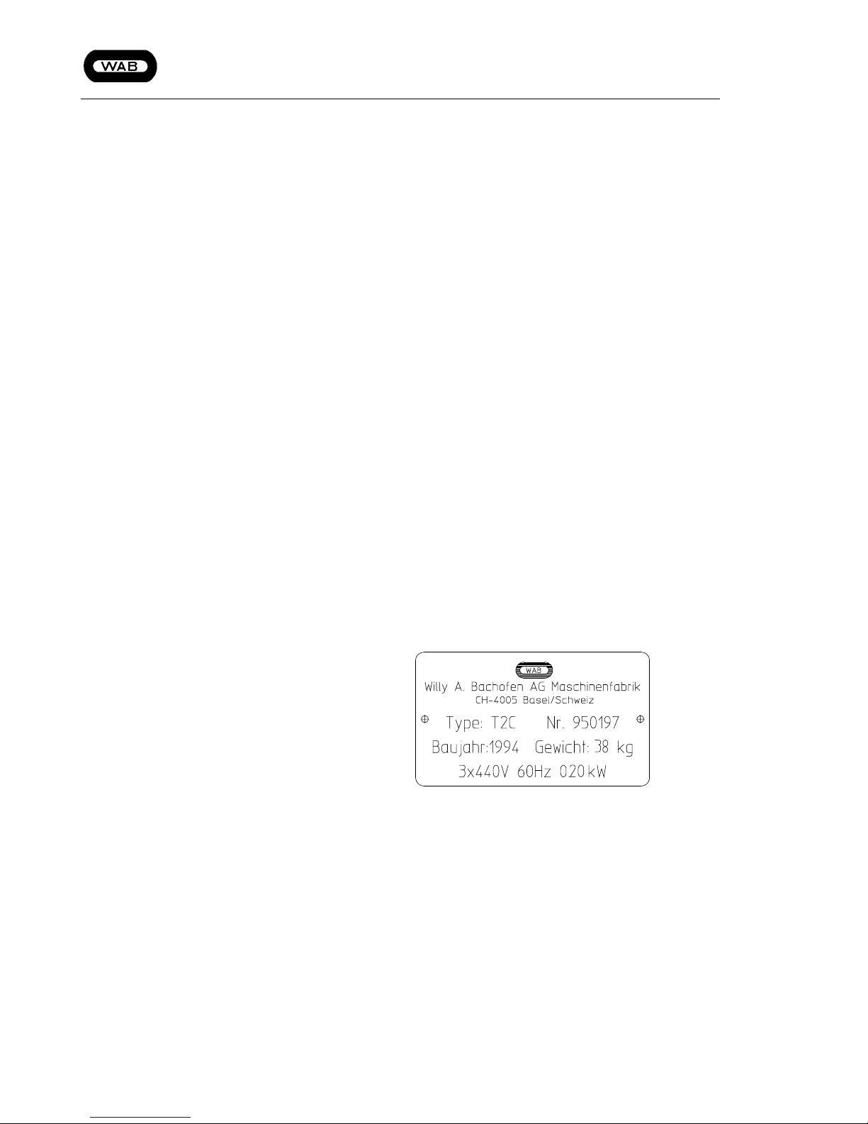
When ordering spare parts please quote:
Machine Type
Machine No.
Drawing no. + Real pos.
Description + Item no.
Required quantity
(Please use also the fax-order in the appendix !)
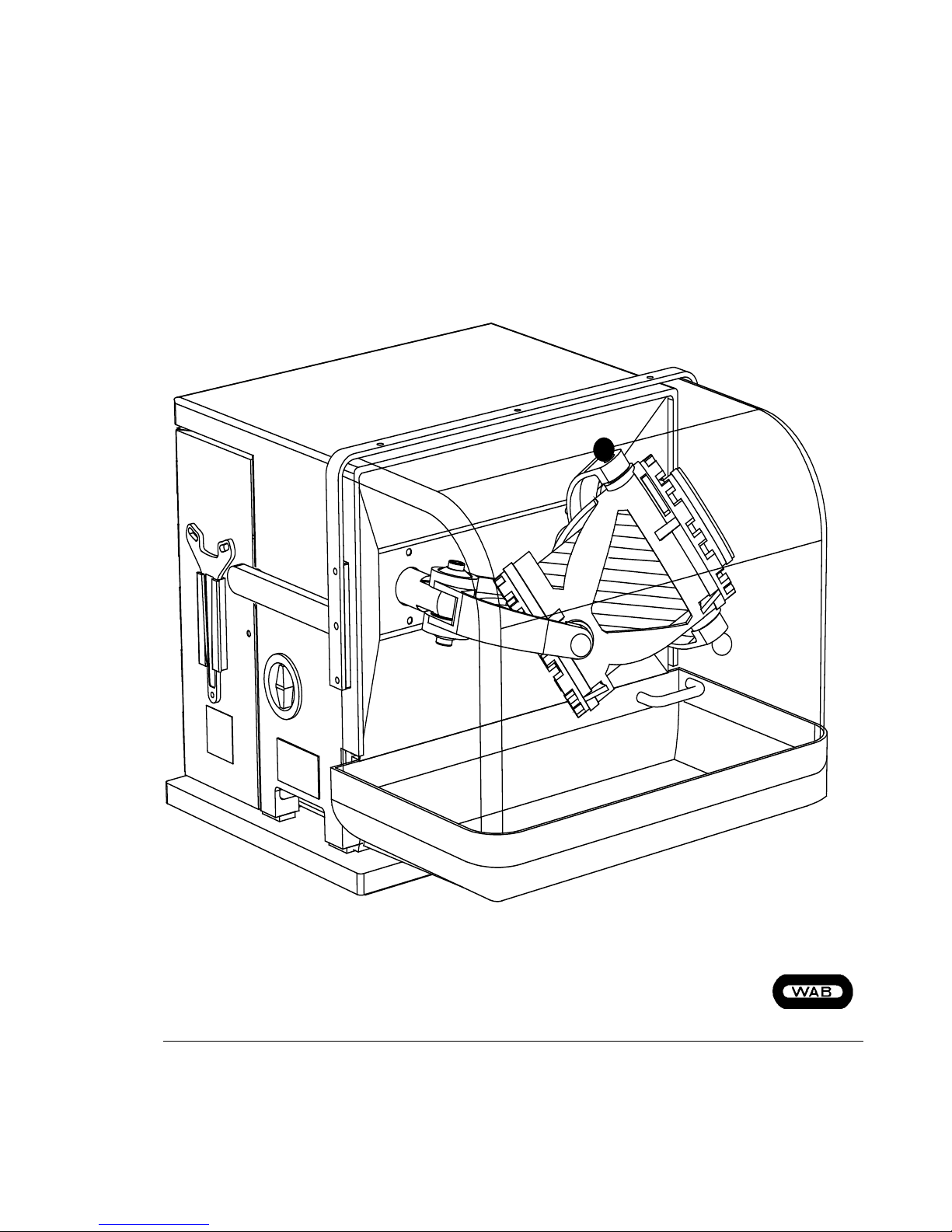
The type plate is situated on the left side of the machine,
underneath the On / Off - switch.
Note
Only original WAB parts must be used. WAB does
not accept any liability for damage resulting from
the use of non WAB spare parts, wearing parts or
accessories.
[Fig. 1]
(Figure is symbolic!)

Seit 1933
Shaker Mixer TURBULA® Type T2 C
Willy A. Bachofen AG • Maschinenfabrik • Utengasse 15-17 • CH-4005 Basel
5
2 Specifications
2.1 Mixer drive
Motor
Operating voltage V, Hz 220, 50
Nominal capacity kW 0.18
Nominal current A 1,1
Power transmission
Antistatic Roundbelt Type POLYCORD
Dimension mm Ø 5 x 660 mm
Endless Flatbelt Type KST
Dimension mm 20 / 1.3 x 624 mm
Chain Type ½“ N-Sp. NR.332/3
Dimension 48 pieces incl. chain joint
Speed min
-1
22 32 46 67 96
(The effective speed of the cage depends on several
influences, and must not correspond to the above mentioned data's.)
2.2 Shaft bearings
Maintenance Self-lubricating, maintenance free
2.3 Mixing service container
Net Mixing service container Litres Up to 2 Litres
Mixing service container-Dimensions max. mm Length 215 mm Ø 130 mm
Mixing service container-filling rate Percent 40 to 99 %
2.4 Control equipment
On / Off - Switch Type QTP10
Make CMC
2.5 Instruments and signal elements
Magnetic circuit breaker Type 108 410, 0 - 250 V, 3 A
(To stop or interrupt start with opened access door)
2.6 Mixer equipment
Rubber straps Type SBR Black (Normal) or Fatex red (Special)
Dimensions mm Outside diam. Ø=89 mm; Outside diam. Ø=410 mm
Mat. thickness Ø=4 mm; Mat. thickness Ø=3 mm
2.7 Noise information
(Emission value to DIN 45635)
Idling dB(A) <70
Working operation dB(A) <70, (Depending on Operation)

Seit 1933
Shaker Mixer TURBULA® Type T2 C
Willy A. Bachofen AG • Maschinenfabrik • Utengasse 15-17 • CH-4005 Basel
6
2.8 Wiring diagram
Wiring diagram No. XXXXX
2.9 Dimensions
Width mm 470
Height (Safety cover retracted) mm 410
Height (Safety cover extended) mm 670
Depth mm 575
2.10 Weight
Weight kg ~38
3 Description
The performance of the TURBULA® shaker mixers is
based on a service proved kinetic principle (reversal
kinematics). The fed charge in the service container is
subjected to the action of a three-dimensional motion,
and therefore mixed.
3.1 Construction details
Mixing service containers
The choice of a suitable service container is free, i.e.
service containers made of plastics, glass, aluminium,
steel, and other materials may be used unless the size
limits imposed by the dimensions of the cage - 130 mm
in diameter and 215 mm long - are exceeded
WARNING
The max. gross weight is 3 kg when using the black
rubber straps (normal) or 5 kg by using the red
rubber straps (special). (Data's refer to max. speed!)
Cage
By using flexible rubber straps, the container is able to
be fixed tight in the cage. Place the free-choice container in the cage, tension the tension collar by using the
tension wrench and the rubber straps will hold the container tight in the right position.
(See chap. 10.1, page 13)
Seit 1933
Shaker Mixer TURBULA® Type T2 C
Willy A. Bachofen AG • Maschinenfabrik • Utengasse 15-17 • CH-4005 Basel
7
4 Application area and correct operation
!
The "Shaker Mixer TURBULA® Type T2 C" may only be used for the task specified. The correct
application is the batch mixing of several substances (liquid - liquid, liquid - solid or solid - solid) or
mechanical-chemical surface treatment.
Machine limiting values:Max. Rpm 96 min
-1
Max. ambient temp Room temperature
Max. load weight The max. gross weight of the container is 3 kg
when using the black rubber straps and 5 kg by
using the red rubber straps.
(Above Data's refer to max. Speed!)
When working lower speeds, it is possible to
work the machine with a max. gross weight of
10 kg.
Instructions for Use
We advise that even within the limits of the machine ratings, the mixing process might produce some excess pres-
sure.
Ensure before operating the machine that the product will not react in an undesirable or even uncontrollable way to
the mixing process.
If you have to expect excess pressure, than you have to use only container which are made for excess pressure op-
erations. While working and open them, ensure to take attention on the several instructions.
Proper use also includes the compliance with the manufacturer's commissioning-, operation- and servicinginstructions (operating instructions), as well as attention to avoidable inappropriate behaviour. The machine
may only be operated and maintained by qualified employees who are familiar with the machine and have been
informed about potential dangers.
Any other uses will be considered improper. The manufacturer does not accept liability for any damages resulting from improper use.
The operating instructions constitute part of the machine delivery and, in the case of resale, must be passed on
to the new owner.
4.1 Residual Dangers
!
In spite of all precautions, some danger may remain. Residual dangers are potential, not very obvious hazards, such as e.g.:
- Fire risk from leakages
- Risks caused by the product such as allergies, skin irritations or burns
- Risk because of malfunctions of the control system
- Risks involved in operating electronic controls
 Loading...